
Page 1 of 1
KATHREIN Digital Systems GmbH • Anton-Kathrein-Straße 1–3 • 83022 Rosenheim • Germany
Rosenheim, 31.03.2019
Information über gesellschaftsrechtliche Änderung
Information about change in corporate legal status
Zum 1. April 2019 geht das Geschäftsfeld „Terrestrial & Satellite Reception“ der
KATHREIN SE (vormals KATHREIN-Werke KG) auf die KATHREIN Digital Systems
GmbH über.
Die neuen Firmendaten lauten ab 01.04.2019 wie folgt:
KATHREIN Digital Systems GmbH
Anton-Kathrein-Str. 1–3
83022 Rosenheim, Deutschland
Steuer-Nr.: 156/117/31083
UST-Ident-Nr.: DE311049363
Registergericht: Traunstein, HRB 25841
______________________________________________________________________________
As of 1 April 2019, KATHREIN SE’s (formerly KATHREIN-WERKE KG) “Terrestrial &
Satellite Reception” business unit will be transferred to KATHREIN Digital Systems
GmbH (limited liability company).
From 1 April 2019, the new company data are:
KATHREIN Digital Systems GmbH
Anton-Kathrein-Str. 1–3
83022 Rosenheim, Germany
Tax ID No.: 156/117/31083
VAT Reg. No.: DE311049363
Commercial Register: Traunstein, HRB 25841
KATHREIN
Digital Systems GmbH
Anton
-Kathrein-Straße 1–3
83022 Rosenheim
Germany
www.kathrein
-ds.com
info
@kathrein-ds.com
Executive Board
:
Michael Auer
Uwe Thumm
US
t-ID-Nr.: DE 311 049 363
Steuer
-Nr.: 156/117/31083
GLN:
40 63242 00000 5
WEEE
-Reg.-Nr.: DE 66199153
Registered Office: Rosenheim, DE
Commerc
ial Register: Traunstein, HRB 25841
Commerzbank AG
IBAN:
DE24 7114 0041 0611 9002 00
BIC:
COBADEFFXXX
936500001

1 / 4
ESO 120 23710023
Reflektorheizung ESO120
Zu dieser Anleitung
Dieses Dokument ist Teil des Produkts. Diese Anleitung beschreibt, wie Sie die Reflektorheizung ESO120 installieren
und anschließen.
► Das Gerät erst installieren und benutzen, nachdem Sie dieses Dokument gelesen und verstanden haben.
► Dieses Dokument während der Lebensdauer des Geräts aufbewahren. Das Dokument an nachfolgende Besitzer und
Benutzer weitergeben.
Die aktuelle Version dieses Anwendungshinweises finden Sie auf der Kathrein-Webseite
www.kathrein.com.
Merkmale
■ flexible Spezialheizmatte mit integrierter Wärmedämmung und PTFE-isolierten Heizelementen
■ gute Wärmeverteilung durch einen optimalen Sitz der Heizmatte am Reflektor
■ einfache Montage
Lieferumfang
● 1xHeizschale mit 3m Kabel (H05RNF)
● Alufolie, gitternetzverstärkt, 4m
● 10xKabelbinder, 360mm
Transport und Lagerung
► Wenn möglich, die Heizmatte in der Originalverpackung transportieren und lagern.
► Die Heizmatte trocken lagern und vor mechanischen Beschädigungen schützen.
► Die Heizmatte im zulässigen Temperaturbereich von –40 bis +80 °C transportieren und lagern. Darauf achten, dass
kein Kondenswasser gebildet wird.
Bestimmungsgemäßer Gebrauch
Die ESO120 ist eine Reflektorheizung für die Antenne CAS120. Sie dient zur Verhinderung von Schnee- und Eisbildung
auf der Antennenreflektoroberfläche, die zu Störungen des Satellitenempfangs führen können.
Jegliche anderweitige Nutzung oder die Nichtbeachtung dieses Anwendungshinweises und der den Geräten beilie-
genden Dokumentationen und Anleitungen hat den Verlust der Gewährleistung bzw. Garantie zur Folge.
Folgende Sachverhalte führen zum Verlust von Garantie- und Haftungsansprüchen gegenüber dem Hersteller:
● unsachgemäße Montage
● Verwendung von nicht aufgeführtem Befestigungsmaterial, wodurch die mechanische Sicherheit nicht gewährleistet
werden kann
● bauliche Veränderungen oder Eingriffe an den Bestandteilen und dem Befestigungszubehör des Sets, wodurch
sowohl die mechanische und elektrische als auch die funktionelle Sicherheit gefährdet werden kann
● Missachtung der Montage- und Sicherheitshinweise in dieser Anleitung
Tipp
Bewahren Sie die Anleitung für später auftretende Fragen sorgfältig auf und geben Sie diese bei Weitergabe
des Geräts an den nächsten Besitzer weiter.

2 / 4
Funktionsbeschreibung
Mit dem Einsatz von Elektroheizungen werden Schnee- und Eisbildung auf der Antennenreflektoroberfläche verhindert,
die zu Störungen des Empfangs führen.
Die Heizung für die Antenne besteht aus einer Spezialheizmatte mit integrierter Wärmedämmung und PTFE-isolierten
Heizelementen.
Die Heizmatte liegt nach der Montage optimal am Reflektor an und garantiert eine gute Wärmeverteilung. In der Heiz-
matte ist ein Temperaturschalter integriert, welcher die Heizung bei 80°C abschaltet, so dass die Anlage direkt an
230V/50Hz betrieben werden kann. Um einen möglichst wirtschaftlichen Betrieb zu gewährleisten, empfehlen wir Ihnen
den Einsatz eines Steuergerätes (ESO005).
Montage- und Sicherheitshinweise
GEFAHR
Lebensgefahr durch Stromschlag!
► Bei Montage alle angeschlossenen Geräte vom Stromnetz trennen.
► Einen Fehlerstrom-Schutzschalter mit einem Nennfehlerstrom von 0,03A einbauen lassen, um die
Vorschriften für Außenanlagen nach DINVDE0100Teil610 einzuhalten.
► Sicherstellen, dass die Montage und der Anschluss nur von qualifiziertem Fachpersonal ausgeführt werden.
► Veränderungen der Elektroinstallation nur von einem Fachmann vornehmen lassen. Niemals eigenmächtige
Veränderungen vornehmen.
WARNUNG
Gefahr schwerer Verletzung bei Montagearbeiten durch Absturz, möglichen Durchbruch oder herabfallende Teile
► Feste und rutschsichere Schuhe tragen.
► Arbeitsbühne verwenden.
► Sicherstellen, dass die montierende/reparierende Person eine sichere Stand- und Halteposition hat.
► Sicherstellen, dass die montierende/reparierende Person schwindelfrei ist und sich sicher auf dem Dach
oder Montageort bewegen kann.
► Sicherstellen, dass das Dach ausreichend stabil ist.
► Sicherstellen, dass sich während der Montage niemand im Bereich unterhalb der Antenne befindet.
► Sicherstellen, dass das Dach und die Aufstiegshilfe trocken, sauber und rutschfest sind.
Reflektorheizung montieren
Erforderliche Werkzeuge und Hilfsmittel
● Messer
● Schere
Heizmatte montieren
1. Antennenrückseite reinigen und entfetten.
2. Heizmatte probeweise an der Antennenrückseite anlegen.
3.
ACHTUNG
Sachschäden durch falsches Anlegen der Heizmatte
Wenn die Heizmatte nicht korrekt an der Antenne angelegt ist, kann sie beim Abziehen der Klebefolie reißen.
► Sicherstellen, dass die Heizmatte korrekt ausgerichtet ist. Dazu die Heizmatte bündig mit der Außenkante
der Antenne abschließen und auf die gleichmäßigen Abstände an der Antennenhalterung achten. Nach
dem Ankleben der Heizmatte ist keine Korrektur möglich!
4. Schutzfolie von der Klebefläche abziehen.
5. Heizmatte kräftig an die Antennenrückseite andrücken.
6. Heizmatte entlang der Ränder komplett mit dem gitternetzverstärkten Aluminiumklebeband gegen das Eindringen
von Feuchtigkeit und Insekten abkleben.

3 / 4
Kabel befestigen
WARNUNG
Lebensgefahr schwerer Verletzung und Sachschäden am Gerät!
► Sicherstellen, dass diese Arbeiten nur durch Fachkräfte durchgeführt werden.
1. Anschlusskabel der Heizschalen am Antennenträger entlang zum Steuergerät führen.
2. Anschlusskabel mit Kabelbindern befestigen.
3. Kabel von unten durch die Verschraubung in das Steuergerät einführen.
4. Netzkabel von unten durch die entsprechende Verschraubung in das Steuergerät einführen.
5. Vor dem Anschluss der Kabel im Schaltschrank die Beheizung auf Durchgangs- und Isolationswiderstand (R) prüfen:
Heizschale
Durchgangswiderstand ±5% Sollwert 70,1–77,5 Ω
Istwert
Isolationswiderstand Sollwert > 999MΩ
Istwert
ACHTUNG
Diese Prüfung auch nach dem Austausch einer defekten Heizschale durchführen.
Bei Verwendung einer Außentemperatursteuerung den Anschluss der Kabel der Montageanleitung der Steuerung
entnehmen, z.B. ESO005.
Wartung
► In regelmäßigen Abständen die einwandfreie Befestigung und den festen Sitz der Heizmatte am Reflektor kontrollieren.
Reparatur und Austausch
Rep and More GmbH
Hauptstrasse 2a
35792 Löhnberg-Oberhausen
Telefon: +49 6477 6123-101
Fax: +49 6477 6123-020
E-Mail:
info@repandmore.com

4 / 4
www.kathrein.com | [email protected]
KATHREIN-Werke KG, Anton-Kathrein-Straße 1-3, 83022 Rosenheim, Germany, Telefon +49 8031 184-0, Fax +49 8031 184-52360
936.5140/-/PSA/1116/DE | Änderungen vorbehalten.
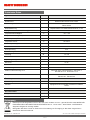
Technische Daten
Typ Einheit ESO120
Bestellnummer 23710023
Heizelement Widerstandsmaterial PTFE-isoliert
Elementträger Aluminiumfolie, Vorderseite mit selbstklebenden
Folienstreifen
Wärmedämmung Luftpolsterfolie mit reflektierender Schicht, 4mm
Spiegeldurchmesser, auf Maß angepasst mm 1200
Temperaturbeständigkeit ºC –40–+80
Empfohlene Montagetemperatur ºC 5–20
Nenntemperatur (Frostschutz) ºC 3
Temperaturschutz ºC 80 Öffner
Betriebsspannung V 230 +6%/–10%; 50–60Hz
Nennstrom A ca. 3
Nennspannung V 230
Nennleistung W ca.500
Leistung W ca. 716
Isolationswiderstand MΩ > 20
Spannungsfestigkeit kV 2,5
Schutzart IP 65
Lebensdauer mind. 10Jahre
Heizmattengewicht kg ca. 0,5
Aufbau und Ausführung nach DIN VDE0100, DINEN60519-1, VDE0721-1
DINEN50173-4, VDE0800-173-4
Entspricht den Normen EN61000-6-1, EN61000-6-3, EN1010-1,
EN60519-1, EN60519-2
Übertemperaturschalter
Ausführung Öffner
Position Spiegelrückseite mittig der Heizfläche im oberen
Drittel
Anschlussart in Reihe zum Heizleiter in Heizmatte verbaut
Anschlusskabel
Länge m 3
Durchmesser mm
2
1
Entsorgung
Elektronische Geräte gehören nicht in den Hausmüll, sondern müssen – gemäß Richtlinie 2002/96/EG DES
EUROPÄISCHEN PARLAMENTS UND DES RATES vom 27. Januar 2003 – über Elektro- und Elektronik-
Altgeräte fachgerecht entsorgt werden.
Bitte geben Sie dieses Gerät am Ende seiner Verwendung zur Entsorgung an den dafür vorgesehenen
öffentlichen Sammelstellen ab.

1 / 4
ESO 120 23710023
ESO 120 Reflector Heating
About This Guide
This document is part of the product. This document describes how to install and connect the ESO120 reflector
heating.
► Do not install or use the device until you have read and understood this document.
► Keep this document for reference throughout the service life of the device. Pass this document on to any new owner
or user.
For the most up-to-date version of this document, go to the Kathrein website
www.kathrein.com.
Features
■ Flexible special heating mat with integrated heat insulation and PTFE isolated heating elements
■ Good heat distribution due to an optimal fit of the heating mat on the reflector
■ Easy installation
Scope of Delivery
● 1xheating tray with a 3m cable (H05RNF)
● Mesh reinforced aluminium foil, 4m
● 10xcable ties, 360mm
Transport and Storage
► If possible, transport and store the heating mat in its original packaging.
► Protect the heating mat against moisture and mechanical damage.
► Transport and store the heating mat only in the permitted temperature range between -40 and +80 °C. Make sure
there is no water condensation build-up.
Intended Use
The ESO120 is a reflector heating for the CAS 120 antenna. It is used to prevent snow and ice formation on the antenna
reflector surface which could lead to interruptions in the satellite reception.
Any other use, or failure to comply with these instructions or documentation and instructions enclosed with the devices,
will result in voiding of warranty or guarantee.
The following circumstances result in the loss of all warranty and liability claims towards the manufacturer:
● Improper Installation
● Use of non-specified mounting materials, which cannot guarantee the mechanical reliability of the antenna system
● Structural changes or interference with the components and mounting accessories in the kit, which could endanger
both the mechanical and functional reliability
● Failure to observe installation and safety instructions in this manual
Tip
Keep these instructions for further reference, and if the unit passes to another owner, pass them on to the
new owner.

2 / 4
Functional Specification
The electric heating prevents snow and ice formation on the antenna reflector surface which lead to interruptions in the
satellite reception.
The heating for the antenna consists of a special heating mat with an integrated heat insulation and PTFE isolated
heating elements.
After installation, the heating mat fits on the reflector in an optimum way and guarantees a good heat distribution. The
heating mat has an integrated temperature switch that turns off the heating at 80°C so that the system can be directly
operated at 230V/50Hz. To ensure that operation is as economical as possible, it is recommended to use a control
device (ESO005).
Installation and Safety Instructions
DANGER
Danger to life from electric shock!
► Disconnect all devices and units from the power supply during installation.
► In order to comply with the regulations for outdoor installation according to DINVDE0100Part610, it is
recommended to have a residual current circuit breaker with a residual current of 0.03 A installed.
► Make sure that the system is installed and connected only by qualified specialist personnel.
► Make sure that modifications to electrical installations are only carried out by a specialist. Do not make any
unauthorised changes yourself.
WARNING
Risk of severe injuries during installation due to falling from the roof, falling through the roof and falling
parts!
► Wear stable shoes with non-slip soles.
► Use a working platform.
►
Make sure that the person carrying out the installation or repair has a secure position to stand and hold on whilst working.
► Make sure that the person carrying out the installation or repair does not suffer from vertigo and can move
around safely on the installation site.
► Make sure that the vehicle roof is sufficiently strong and stable.
► Make sure that there is nobody underneath the antenna during installation/dismantling.
► Make sure that the roof and climbing aid are dry, clean and non-slip.
Installing the Reflector Heating
Required tools and equipment
● Knife
● Scissors
Installing the Heating Mat
1. Clean and degrease the antenna back panel.
2. Hold the heating mat on the antenna back panel to test the position.
3.
NOTICE
Risk of material damage due to the incorrect attachment of the heating mat!
If the heating mat is not attached to the antenna in a correct way, it can tear while the adhesive film is being removed.
► Make sure that the heating mat is aligned in the correct way. To do so, place the heating mat flush with
the outer edge of the antenna and pay attention to the equal distance on the antenna bracket. After the
heating mat has been secured, the correction is no longer possible!
4. Remove the protective film from the adhesive area.
5. Press the heating mat firmly to the antenna back panel.
6. To prevent moisture and insects from entering the heating mat, adhere the mesh-reinforced aluminium foil all along
the edges of the mat.

3 / 4
Connecting the Cables
WARNING
Risk of severe injuries or material damage to the device!
► Make sure that this work is carried out only by qualified specialist personnel.
1. Run the connection cables of the heating trays along the antenna carrier to the control device.
2. Use cable ties to attach the connection cables.
3. Run the cables from the bottom through the screw connection into the control device.
4. Run the mains cable from the bottom through the corresponding screw connection into the control device.
5. Test the heating for contact resistance and insulation resistance (R) before connecting the cables in the control
cabinet.
Heating tray
Contact resistance ±5% Target
value
70.1–77.5 Ω
Actual
value
Insulation resistance Target
value
> 999MΩ
Actual
value
NOTICE
These tests should be repeated after replacement of a defective heating tray.
When using an outside temperature control, the corresponding cabling instructions can be found in the installa-
tion manual of that control device, e.g. ESO005.
Maintenance
► Check the correct attachment and seating of the heater mat on the reflector at regular intervals.
Repair and Replacement
Rep and More GmbH
Hauptstrasse 2a
35792 Löhnberg-Oberhausen, Germany
Phone: +49 6477 6123-101
Fax: +49 6477 6123-020
Email:
info@repandmore.com

4 / 4
www.kathrein.com | [email protected]
KATHREIN-Werke KG, Anton-Kathrein-Straße 1-3, 83022 Rosenheim, Germany, Phone +49 8031 184-0, Fax +49 8031 184-52360
936.5140/-/PSA/1016/GB |Subject to change.
Technical Data
Type Unit ESO120
Order number 23710023
Heating element Resistance material PTFE isolated
Element carrier Aluminium foil, self-adhesive foil strips at the front
Heat insulation Bubble wrap with a reflective layer, 4 mm
Reflector diameter, marked down to exact size mm 1200
Temperature resistance ºC -40–+80
Recommended installation temperature ºC 5–20
Nominal temperature (frost protection) ºC 3
Temperature protection ºC 80 opener
Operating voltage V 230 +6%/–10%; 50–60Hz
Nominal current A approx. 3
Nominal voltage V 230
Rated power W approx. 500
Power W approx. 716
Insulation resistance MΩ > 20
Dielectric strength kV 2.5
Protection class IP 65
Working life min. 10 years
Weight of the heating mat kg approx. 0.5
Design and construction type according to DIN VDE0100, DINEN60519-1, VDE0721-1
DINEN50173-4, VDE0800-173-4
Corresponds to the standards EN61000-6-1, EN61000-6-3, EN1010-1,
EN60519-1, EN60519-2
Excess temperature cut-out
Design Opener
Position Reflector back panel in the middle of the heating area
in the top third
Type of connection Connected in series to the heating element in the
heating mat
Connection cables
Length m 3
Diameter mm
2
1
Disposal
Electronic equipment is not domestic waste – in accordance with directive 2002/96/EC OF THE EUROPEAN
PARLIAMENT AND THE COUNCIL dated 27th January 2003 concerning used electrical and electronic
appliances, it must be disposed of properly.
At the end of its service life, take this unit for disposal at a designated public collection point.
-
 1
1
-
 2
2
-
 3
3
-
 4
4
-
 5
5
-
 6
6
-
 7
7
-
 8
8
-
 9
9


Kathrein ESO 120 User manual
- Type
- User manual
- This manual is also suitable for
Ask a question and I''ll find the answer in the document
Finding information in a document is now easier with AI
in other languages
- Deutsch: Kathrein ESO 120 Benutzerhandbuch
Related papers
-
Kathrein ESO 005 User manual
-
-
-
-
-
Kathrein CAS 06 User manual
-
-
-
-
Kathrein EXIP 4124 User manual
Other documents
-
Megasat Traveller-Man User manual
-
Lenz heat bag 1.0 User manual
-
STIEBEL ELTRON FTB 160 Operation Instruction
-
Westfalia 978933 Electric Heating Mat User manual
-
Dimplex HMTS Owner's manual
-
Maxview MXL050/KIT1 Operating instructions
-
 frenzelit hicoTHERM 36-60 Installation And Operating Instructions Manual
-
BriskHeat SRL5 Custom Series User manual
-
 Mi-Heat MI-HEAT 17/5 Black Gold Heating Mat User manual
-
 CityCom CCA 600G User manual


