Page is loading ...

Page 1 of 1
KATHREIN Digital Systems GmbH • Anton-Kathrein-Straße 1–3 • 83022 Rosenheim • Germany
Rosenheim, 31.03.2019
Information über gesellschaftsrechtliche Änderung
Information about change in corporate legal status
Zum 1. April 2019 geht das Geschäftsfeld „Terrestrial & Satellite Reception“ der
KATHREIN SE (vormals KATHREIN-Werke KG) auf die KATHREIN Digital Systems
GmbH über.
Die neuen Firmendaten lauten ab 01.04.2019 wie folgt:
KATHREIN Digital Systems GmbH
Anton-Kathrein-Str. 1–3
83022 Rosenheim, Deutschland
Steuer-Nr.: 156/117/31083
UST-Ident-Nr.: DE311049363
Registergericht: Traunstein, HRB 25841
______________________________________________________________________________
As of 1 April 2019, KATHREIN SE’s (formerly KATHREIN-WERKE KG) “Terrestrial &
Satellite Reception” business unit will be transferred to KATHREIN Digital Systems
GmbH (limited liability company).
From 1 April 2019, the new company data are:
KATHREIN Digital Systems GmbH
Anton-Kathrein-Str. 1–3
83022 Rosenheim, Germany
Tax ID No.: 156/117/31083
VAT Reg. No.: DE311049363
Commercial Register: Traunstein, HRB 25841
KATHREIN
Digital Systems GmbH
Anton
-Kathrein-Straße 1–3
83022 Rosenheim
Germany
www.kathrein
-ds.com
info
@kathrein-ds.com
Executive Board
:
Michael Auer
Uwe Thumm
US
t-ID-Nr.: DE 311 049 363
Steuer
-Nr.: 156/117/31083
GLN:
40 63242 00000 5
WEEE
-Reg.-Nr.: DE 66199153
Registered Office: Rosenheim, DE
Commerc
ial Register: Traunstein, HRB 25841
Commerzbank AG
IBAN:
DE24 7114 0041 0611 9002 00
BIC:
COBADEFFXXX
936500001

1 / 4
Zu dieser Anleitung
Dieses Dokument ist Teil des Produkts.
► Die Speisesystemhalterung erst installieren und
benutzen, nachdem Sie diese Anleitung gelesen und
verstanden haben.
► Die in dieser Anleitung beschriebenen Maßnahmen
immer in der angegebenen Reihenfolge durchführen.
Tipp
Bewahren Sie die Anleitung für später auftre-
tende Fragen sorgfältig auf und legen Sie
diese dem Gerät bei Weitergabe an den
nächsten Benutzer bei.
Die aktuelle Version dieses Dokuments nden Sie auf
www.kathrein.com.
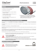
Bestimmungsgemäßer Gebrauch
Die Speisesystemhalterung ZAS124 C dient zur mecha-
nischen Adaption eines oder mehrere Kompaktspeisesys-
teme an die 1,2 m Offset-Parabolantenne CAS124.
Bei anderweitiger Nutzung oder Nichtbeachtung dieses
Dokuments erlöschen die Garantie und die Gewährleistung.
Merkmale
■ geeignet für die Parabolantenne CAS124
■ Es können Kathrein-Speisesysteme in Kompakt- oder
modularer Bauform verwendet werden, z.B. UAS584.
Lieferumfang
■ ZAS124 C
■ Gebrauchsanleitung
Abb. 1: ZAS124C
Anschlag im Klemmkörper
Empfangssystem(e)
Feedhalterung
Klemmkörper2 Schellen
Abb. 2: Montage der ZAS 124C
Montage
1. Auslegerrohr bis auf Anschlag in den Klemmkörper der
montierten Antenne einsetzen (Abb. 2).
2. Zwei Schließschellen mit dem Anziehdrehmoment von 17Nm
festschrauben (Abb. 2).
3. Feedhalterung mit dem Anziehdrehmoment von 17Nm bis auf
Anschlag mit dem Auslegerrohr montieren (Abb. 2).
4. Das Empfangssystem oder die Empfangssysteme entsprechend
den Einkerbungen der Trägerplatte positionieren (Abb. 3).
Monofeed-Anwendung Multifeed-Anwendung
Abb. 3: Empfangssystem(e) positionieren
ZAS124 C 23710026
WICHTIG
Vor Gebrauch
sorgfältig
lesen!
Speisesystemhalterung

2 / 4
5.
Den Neigungswinkel V der schwenkbaren Speisesystemhalterung
(Abb. rechts) in Abhängigkeit vom Antennenstandpunkt (Länge,
Breite) und dem Orbitalabstandswinkel der beiden äußeren Satelliten
(3° oder 6°) gemäß Tabelle 9362131 einstellen
. Dazu:
– Die M8-Innensechskantschraube (① in Abb. 4) lösen.
– Den Neigungswinkel einstellen.
– M8-Innensechskantschraube festziehen.
1
Messempfänger
Schwenkteil der
Multifeedhalterung
Abb. 4: Neigungswinkel einstellen
Antenne ausrichten
1. Zum Einstellen auf den Satelliten einen geeigneten Mess-
empfänger mit einem Koaxialkabel an einem der äußeren
Empfangssysteme anschließen, außer es soll ein anderes
Empfangssystem bevorzugt werden. Für die Auswahl der
Satelliten, siehe AW Aufnahmeplatte.
2. Elevation und Azimut schrittweise einstellen, bis der größte
Empfangspegel erreicht ist.
Neigung (Elevation) einstellen
– Löse
n Sie die Schraube an der Neigungsskala (Elevation)
links und rechts an der Halterung mit dem der Parabolan-
tenne beiliegenden Innensechskantschlüssel
(① in Abb. 5).
– Stellen Sie dann die Neigung (Elevation) ein. Den
genauen Elevationswinkel für Ihren Standort nden Sie in
der Anleitung für das Speisesystem (LNB).
– Ziehen Sie im Anschluss daran erst nur eine der
Schrauben an der Neigungsskala wieder handfest an.
Richtung (Azimut) einstellen
Für die folgenden Schritte benötigen Sie gegebenenfalls
einen Helfer, falls Sie nicht selbst an einem Antennenmess-
gerät oder Bildschirm mit angeschlossenem Satelliten-
Receiver das Ergebnis der Ausrichtarbeiten beobachten
können. Eine exakte Ausrichtung der Antenne kann nur
mittels eines digitalen Antennenmessgerätes geschehen.
Fragen Sie hierzu Ihren Fachhändler.
– Am Satellitenreceiver einen bekannten Programm-
platz einstellen, um kontrollieren zu können, ob der
gewünschte Satellit „getroffen“ wurde.
–
Die Muttern an der Mastschelle leicht löse
n (① in Abb. 6).
– Die Antenne grob in Richtung Süden drehen.
– Die Antenne langsam um die Mittelachse nach links und
rechts drehen, bis das eingestellte Programm am besten
zu empfangen ist.
– Die Muttern erst nur soweit festziehen, dass sich die
Antenne nicht verdrehen kann.
Abb. 5: Elevation einstellen
Abb. 6: Azimut einstellen
1
1

3 / 4
3. Polarisation am angeschlossenen Speisesystem auf opti-
malen Empfangspegel einstellen. Dabei die folgende theore-
tische Einstellung beachten:
Polwinkel
neu
= Polwinkel
TAB
– V
Polwinkel
neu
: am Empfangssystem einzustellender Polari-
sationswinkel
Polwinkel
TAB
: Polarisationswinkel aus der Tabelle, die dem
Empfangssystem beigelegt ist
V: Neigungswinkel der schwenkbaren Speisesystemhalterung
gemäß Tabellen 9362131.
4. Polarisation bei den anderen Systemen vornehmen, bis der
max. Empfangspegel erreicht ist.
5. Falls notwendig, die Antenne in Elevation und Azimut nach-
justieren.
– Die Schraube an der Neigungsskala lösen.
– Die Antenne leicht nach oben und unten schwenken, bis
Sie entweder am Antennenmessgerät das stärkste Anten-
nensignal messen oder bei optischer Beurteilung am
Bildschirm den besten Bildeindruck erzielen: Hierzu die
Antenne soweit nach oben und unten schwenken, bis Sie
jeweils an die Grenze kommen, wo die ersten sogenann-
ten „Fischchen“ (analog) oder „Klötzchen“ (digital) am
Bildschirm erscheinen.
– Die Antenne in die Mitte zwischen diesen beiden Grenz-
punkten stellen.
– Abwechselnd die Richtung (Azimut) und Neigung (Ele-
vation) korrigieren, bis sich das Mess- oder Bildergebnis
nicht mehr verbessert.
Hinweis:
Beim Festdrehen der Muttern an der Schließschelle kann sich
die Antenne leicht verdrehen! Dies sollten Sie bei der Feineinstel-
lung beachten (und eventuell für eine ganz genaue Einstellung
ausnutzen).
Tipp
Bei nur zwei Satelliten die Antenne auf den Satelli-
ten ausrichten, der die pegelschwächeren Signale
sendet.
6. Nach der Justierung alle Schrauben anziehen.
Abb. 7: Feineinstellung

4 / 4
www.kathrein.com | [email protected]
KATHREIN-Werke KG, Anton-Kathrein-Straße 1-3, 83022 Rosenheim, Germany, Phone +49 8031 184-0, Fax +49 8031 184-52360
935.5412/-/PSA/0317/DE-GB | Änderungen vorbehalten. Subject to change.
Reparatur und Austausch
Reparaturstelle
Rep and More GmbH
Hauptstraße 2a
35798 Löhnberg-Oberhausen
Telefon +49 6477 6123 101
Fax +49 6477 6123 020
E-Mail:
service-kathrein@repandmore.com
Entsorgung
► Metallteile umweltgerecht entsorgen.
► Die vor Ort gültigen Vorschriften beachten.

5 / 8
About This Guide
This document is part of the product.
► Do not install or use this device until you have read and
understood this document.
► Perform all operating steps described in this manual in
the specied sequence.
Tip
Keep these instructions for further reference,
and if the unit passes to another owner, pass
them on to the new owner.
For the most up-to-date version of this document, go to
www.kathrein.com.
Intended Use
The ZAS124 C feed system support is used to mecha-
nically adapt one or more compact feed systems to the
CAS 124 offset parabolic antenna with a 1.2 m diameter.
If it is used in any other way or if the provisions of this
document are disregarded, the guarantee and warranty will
become void.
Features
■ Suitable for the CAS 124 parabolic antenna
■ It is possible to use Kathrein feed systems of the
compact or modular design, e.g. UAS 584
Scope of Delivery
■ ZAS 124 C
■ Instructions for Use
Fig. 1: ZAS124 C
Anschlag im Klemmkörper
Empfangssystem(e)
Feedhalterung
Klemmkörper2 Schellen
Fig. 2: Installation of the ZAS 124 C
Installation
1. Insert the boom tube into the clamp body of the mounted
antenna as far as it will go (Fig. 2).
2. Tighten the two clamps to a torque of 17Nm (Fig. 2).
3. Insert the feed bracket into the boom tube as far as it will go
(Fig. 2) and tighten it to a torque of 17 Nm.
4. Position the reception system/s according to the indentations
on the carrier plate (Fig. 3).
Monofeed-Anwendung Multifeed-Anwendung
Fig. 3: Position the reception system/s
ZAS124 C 23710026
IMPORTANT
Read carefully
before use!
Feed System Support

6 / 8
5.
Set the inclination angle V of the tiltable feed system support
(gure on the right) depending on the antenna location (longitude,
latitude) and the orbital spacing angle of the two outer satellites
(3° or 6°) according to table 9362131
. To do so:
– Loosen the M8 socket-head screw (① in Fig. 4).
– Set the inclination angle.
– Tighten the M8 socket-head screw.
1
Messempfänger
Schwenkteil der
Multifeedhalterung
Fig. 4: Adjusting the inclination angle
Aligning the Antenna
1. For alignment to the satellite, connect a suitable signal meter
using a coax cable to one of the outer reception systems,
unless a different reception system is preferred. For selecting
the satellites, see mounting plate manual.
2. Gradually adjust elevation and azimuth until you reach the
best reception.
Setting the inclination (elevation)
– Use the hexagon key supplied with the parabolic antenna
to slacken the two screws on each side of the inclination
scale (elevation) on the left and right of the clamp (① in
Fig. 5).
– Then set the inclination (elevation). You will nd the
exact elevation angle for your location in the feed system
manual (LNB).
– After this, retighten rst one of the bolts on the inclination
scale nger-tight.
Setting the direction (azimuth)
If you yourself are unable whilst performing the adjustments
to read the results of the alignment work on an antenna
meter or screen connected to the satellite receiver, you may
need an assistant for the following steps. The precise align-
ment of the antenna can be achieved only if a digital antenna
meter is used. Ask your dealer about this.
– Set the satellite receiver to a known channel so that you
can check whether you have really "locked on" to the
desired satellite.
–
Slightly loosen the wing nuts on the mast clip
(① in Fig. 6).
– Turn the antenna so that it faces roughly south.
– Slowly turn the antenna about its central axis to the
left and right until the best reception is obtained for the
selected channel.
– Tighten the wing nuts just enough to prevent the antenna
from turning.
Fig. 5: Adjusting the elevation
Fig. 6: Adjusting the azimuth
1
1

7 / 8
3. Set the polarisation on the connected feed system to obtain
the best reception using the following formula:
pole angle
new
= pole angle
TAB
– V
PA
new
: polarisation angle to be set on the reception system
PA
TAB
: Polarisation angle according to the table included with
the reception system
V: Inclination angle of the tiltable feed system support accor-
ding to table 9362131.
4. Set the polarisation on the other systems until the best
reception is obtained.
5. If necessary, re-adjust the elevation and azimuth of the
antenna.
– Loosen the screw on the inclination scale.
– Tilt the antenna slightly upwards and downwards until
either the antenna meter shows the strongest antenna
signal or visual assessment concludes that the best
picture has been achieved: To do this, tilt the antenna
far enough upwards and downwards to get to the limits
where the rst "little sh" (analogue) or "little blocks"
(digital) appear on the screen.
– Position the antenna midway between these two points.
– Alternate correcting the direction (azimuth) and inclination
(elevation) until the measured results or the picture quality
show no further improvement.
Note:
When tightening the nuts on the clamp, there is a risk of the
antenna turning slightly. You should allow for this when doing the
ne adjustment (and if necessary make use of it when starting
the adjustment operation all over again).
Tip
In case of only two satellites, the antenna should
be aligned towards the satellite which is transmit-
ting the weakest signal.
6. Tighten all screws after the adjustment.
Fig. 7: Fine adjustment

8 / 8
www.kathrein.com | [email protected]
KATHREIN-Werke KG, Anton-Kathrein-Straße 1-3, 83022 Rosenheim, Germany, Phone +49 8031 184-0, Fax +49 8031 184-52360
935.5412/-/PSA/0317/DE-GB | Änderungen vorbehalten. Subject to change.
Repair and Replacement
Repair centre
Rep and More GmbH
Hauptstraße 2a
35798 Löhnberg-Oberhausen, Germany
Phone +49 6477 6123 101
Fax +49 6477 6123 020
Email:
service-kathrein@repandmore.com
Disposal
► Dispose of metal parts in an environmentally responsible way.
► Pay attention to the local regulations.
/