Page is loading ...

Page 1 of 1
KATHREIN Digital Systems GmbH • Anton-Kathrein-Straße 1–3 • 83022 Rosenheim • Germany
Rosenheim, 31.03.2019
Information über gesellschaftsrechtliche Änderung
Information about change in corporate legal status
Zum 1. April 2019 geht das Geschäftsfeld „Terrestrial & Satellite Reception“ der
KATHREIN SE (vormals KATHREIN-Werke KG) auf die KATHREIN Digital Systems
GmbH über.
Die neuen Firmendaten lauten ab 01.04.2019 wie folgt:
KATHREIN Digital Systems GmbH
Anton-Kathrein-Str. 1–3
83022 Rosenheim, Deutschland
Steuer-Nr.: 156/117/31083
UST-Ident-Nr.: DE311049363
Registergericht: Traunstein, HRB 25841
______________________________________________________________________________
As of 1 April 2019, KATHREIN SE’s (formerly KATHREIN-WERKE KG) “Terrestrial &
Satellite Reception” business unit will be transferred to KATHREIN Digital Systems
GmbH (limited liability company).
From 1 April 2019, the new company data are:
KATHREIN Digital Systems GmbH
Anton-Kathrein-Str. 1–3
83022 Rosenheim, Germany
Tax ID No.: 156/117/31083
VAT Reg. No.: DE311049363
Commercial Register: Traunstein, HRB 25841
KATHREIN
Digital Systems GmbH
Anton
-Kathrein-Straße 1–3
83022 Rosenheim
Germany
www.kathrein
-ds.com
info
@kathrein-ds.com
Executive Board
:
Michael Auer
Uwe Thumm
US
t-ID-Nr.: DE 311 049 363
Steuer
-Nr.: 156/117/31083
GLN:
40 63242 00000 5
WEEE
-Reg.-Nr.: DE 66199153
Registered Office: Rosenheim, DE
Commerc
ial Register: Traunstein, HRB 25841
Commerzbank AG
IBAN:
DE24 7114 0041 0611 9002 00
BIC:
COBADEFFXXX
936500001

1 / 10
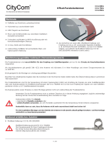
Offset-Parabolantennen
Merkmale
■
Reflektor aus Aluminium, pulverbeschichtet
■
Rückenteil aus verzinktem Stahlblech
■
LNB-Tragarm aus Aluminium
■
Mast- und Schließschellen aus verzinktem Stahlblech
(komplett vormontiert)
■
Schrauben und Muttern in Inox-Ausführung
■
Farbe: KEA650/750/850/1000 – graphit (ähnl. RAL7012),
rotbraun (ähnl. RAL8012), weiß (ähnl. RAL9002)
■
Lieferumfang: Reflektor mit vormontierter Mast- und Speise-
systemhalterung
■
Nur KEA750/850/1000: Aufnahme von zwei LNBs (Multi-
feed-Empfang) zum Empfang von bis zu 6° auseinander
liegenden Satelliten, z.B.ASTRA/EUTELSAT HOTBIRD. Dazu
ist zusätzlich die Multifeed-Halterung KEZ02 (BN20010056)
erforderlich (siehe Optional erhältliches Zubehör).
KEA 650
KEA 750
KEA 850
KEA 1000
Bestimmungsgemäßer Gebrauch
Die Parabolantennen sind ausschließlich für den Empfang von Satellitensignalen und nur für den Einsatz als Haushaltsantenne vorge-
sehen. Als Haushaltsantenne gilt gemäß DINEN60728-11 eine Antenne mit höchstens 6 m freier Mastlänge und einem Einspannmo-
ment bis zu 1650Nm.
Die Parabolantennen sind für die Verwendung mit einem Speisesystem (LNB) zum Empfang der Signale von einer Satellitenposi-
tion oder mit zwei Speisesystemen für Multifeed-Anwendungen zum Empfang der Signale von zwei Satellitenpositionen mit bis zu
6°
Satellitenabstand konzipiert (bei KEA750/850/1000 mit KEZ02).
● Nicht geeignet für die Montage an schwingungsanfälligen Bauwerken.
● Unbedingt die Angaben über die maximale Windgeschwindigkeit in den Technischen Daten beachten. Bei Überschreitung dieser
Geschwindigkeit können Teile abbrechen!
● Die Speisesysteme sowie Hinweise zu deren Montage gehören nicht zum Lieferumfang der Parabolantenne.
● Verwenden Sie die Parabolantenne nicht zu anderen Zwecken als in dieser Anleitung angegeben! Insbesondere dürfen Sie niemals
– irgendwelche Bauteile verändern oder
– andere Bauteile verwenden, als vom Hersteller ausdrücklich für die Verwendung mit der Antenne vorgesehen.
Andernfalls kann es sein, dass die Antenne nicht mehr ausreichend stabil und sicher ist!
● Für die Installation/Montage und den Betrieb der Antenne die jeweils aktuell gültige Gesetzes- und Normenlage verbindlich
beachten/anwenden.
Jegliche anderweitige Nutzung oder die Nichtbeachtung dieses Anwendungshinweises hat den Verlust der Gewährleistung bzw.
Garantie zur Folge.
Tipp
Bewahren Sie die Anleitung für später auftretende Fragen sorgfältig auf und legen Sie diese dem Gerät bei Weitergabe
der Antenne an den nächsten Benutzer bei.
Lieferumfang
Lieferumfang KEA 650/750: Lieferumfang KEA 850/1000:
● Tragarm vormontiert
● Reflektor
● 4x Schraube M6x35 Inox
● 4x selbstichernde Mutter M6 Inox
● Gebrauchsanleitung
● Tragarm vormontiert
● Reflektor
● 6x Schraube M6x35 Inox
● 6x selbstichernde Mutter M6 Inox
● Gebrauchsanleitung

2 / 10
Offset-Parabolantennen
Optional erhältliches Zubehör
■
Multifeed-Halterung KEZ02, BN 20010056
Tipp
Multifeed-Halterung passend für KEA750/850/1000. Die Elevations-
werte können Sie mit der Azimut-/Elevationsberechnung im Internet auf
http://www.kathrein.de/content/sat/satpos/satpos_suche.cfm
ermitteln.
Sicherheitshinweise
Vor der Montage, dem Anschluss und der Verwendung der Parabolantenne unbedingt die Hinweise in dieser Anleitung beachten!
Wenn Sie die Hinweise nicht beachten,
● können durch Fehlverhalten Gefahren für Ihre Gesundheit und Ihr Leben entstehen,
● können durch Fehler bei der Montage oder beim Anschluss Schäden an der Antenne oder am Montageort entstehen,
● haftet der Hersteller nicht für darauf zurückzuführende Fehlfunktionen und Schäden!
GEFAHR
Lebensgefahr durch Stromschlag bei Berührung von elektrischen Einrichtungen!
► Niemals Antennen unter oder in der Nähe von Freileitungen montieren.
► Bei Montage mindestens 1 m Abstand zu allen elektrischen Einrichtungen halten.
► Niemals bei aufziehendem Gewitter oder während eines Gewitters an Antennenanlagen arbeiten.
WARNUNG
Gefahr schwerer Verletzung bei Montagearbeiten auf dem Dach!
► Feste und rutschsichere Schuhe tragen.
► Dächer oder absturzgefährdete Stellen nur mit einem ordnungsgemäß angelegten intakten Sicherheitsgurt betreten
oder Arbeitsbühne verwenden.
► Sicherstellen, dass das Dach und die Aufstiegshilfe trocken, sauber und rutschfest sind.
►
Sicherstellen, dass die montierende/reparierende Person eine sichere Stand- und Halteposition hat. Evtl. am Dach angurten.
► Sicherstellen, dass die montierende/reparierende Person schwindelfrei ist und sich sicher auf dem Dach bewegen
kann.
► Sicherstellen, dass das Dach ausreichend stabil ist und das Gewicht der montierenden/reparierenden Person tragen
kann. Im Zweifelsfall einen qualifizierten Fachhändler oder einen Fachmann des Dachhandwerks kontaktieren.
► Sicherstellen, dass sich während der Montage/Reparatur niemand unterhalb des Montageortes befindet.
► Die jeweiligen landesspezifischen Sicherheitsbestimmungen und aktuellen Normen, z.B. DINEN60728-11 beachten.
WARNUNG
Gefahr schwerer Verletzung durch Brandgefahr bei atmosphärischen Überspannungen (statische Aufladung) oder
Blitzentladungen (z.B. Gewitter)!
►
Niemals Antennen auf Gebäuden mit leicht entzündbaren Dachabdeckungen, z.B. Stroh, Reet oder ähnlichen Materialien montieren.
Montageort wählen
Der richtige Montageort ist entscheidend darüber, ob die Parabolantenne sicher aufgebaut ist und optimal funktionieren kann. Bei der
Wahl des Montageortes Folgendes beachten:
● Bauwerktypische Besonderheiten berücksichtigen. Bei Montage an Dach- und Gebäudekanten und zylindrischen Bauwerken ist
gemäß DINEN1991-1-4 bzw. DIN4131 mit erhöhten Wind oder Schwingungsbelastungen zu rechnen.
● Die dynamischen Eigenschaften der Antenne und des Bauwerks können sich gegenseitig beeinflussen und negativ verändern.
● Bei Nichtbeachtung kann eine Überschreitung der unter den technischen Daten genannten Windgeschwindigkeit oder Schwin-
gungsfestigkeit auftreten.
Tipp
Die Parabolantenne muss nicht unbedingt auf dem Dach montiert werden, weil es nicht auf die Höhe über Grund
ankommt, sondern nur auf die freie Sicht zum Satelliten. Deshalb kann ein geeigneter Montageort z.B. auch im Garten,
auf dem Balkon, auf der Terrasse, an einer Fassade oder an einer Garage zu finden sein.
Wenn möglich, die Antenne nicht auf dem Dach montieren. Somit verringern Sie Ihren Arbeitsaufwand und die Gefahren
bei Montagearbeiten auf dem Dach!

3 / 10
Offset-Parabolantennen
Für einen einwandfreien Empfang muss eine freie Sicht in Rich-
tung Süden (±20°) bei einer Erhebung von etwa 30° gewähr-
leistet sein. Dann stehen Ihnen folgende Satelliten zur Auswahl:
1 TÜRKSAT
*)
42° Ost 5 EUTELSAT W 2 16° Ost
2 ASTRA 2-Gruppe 28,2° Ost 6 EUTELSAT-
HOTBIRD
13° Ost
3 ASTRA 3-Gruppe 23,5° Ost 7 EUTELSAT W 1 10° Ost
4 ASTRA 1-Gruppe 19,2° Ost 8 HISPASAT 30° West
Darauf achten, dass sich keine Hindernisse zwischen der Para-
bolantenne und dem jeweiligen Satelliten befinden (z.B. Bäume,
Dach- oder Hausecken, andere Antennen). Diese können den
Empfang so beeinträchtigen, dass dieser bei ungünstiger Witte-
rungslage völlig ausfällt.
*)
Empfang abhängig vom jeweiligen Standort und der Ausleuchtzone
des Satelliten
Antenne montieren
Bei der Montage des Antennenträgers (Mast oder Wandausleger)
darauf achten, dass dieser senkrecht steht. Andernfalls kann die
Ausrichtung der Antenne auf den Satelliten zu Schwierigkeiten
führen.
Anforderungen an den Antennenträger
● Nur Masten oder Tragrohre verwenden, die speziell für
Antennenmontage geeignet sind. Andere Rohre oder Träger
haben zumeist nicht die erforderliche Festigkeit bei Wind-
und Wettereinflüssen.
● Bei der Mastmontage einen Rohrdurchmesser zwischen
30bis90mm mit einer Wanddicke von mindestens 2mm
wählen. Bei Wandmontage empfehlen wir die Verwendung
der Kathrein-Wandhalterungen ZAS60 oder ZAS61.
● Bei einer Mastmontage auf dem Dach, den Mast über
mindestens 1/6 der freien Länge einspannen (im Beispiel
unten rechts sind dies 0,7m).
Mehrere Antennen an einem Antennenträger:
● Die Parabolantenne am Mast ganz unten montieren, um das
Biegemoment an der Einspannstelle gering zu halten.
● Keinesfalls die maximale Belastbarkeit für den Mast oder
Masthalter überschreiten, welche in deren technischen Daten
angegeben ist. Die maximale Belastbarkeit ist ausreichend
berücksichtigt, wenn die Antennenanlage so ausführt ist wie
im Beispiel rechts, und übliche Haushaltsantennen sowie aus
dem Fachhandel bezogene Mastbauteile verwendet werden
(Rohr in Stahlgüte S355 (St52) mit Außendurchmesser
60mm und Wanddicke 2,5mm an der Masteinspannstelle –
z.B. ZSH59 von Kathrein) .
Abb. 1: Montageort wählen
Ø 30 – 90 mm
Abb. 2: Antennenträger wählen
Reflektormitte
Abb. 3: Mehrere Antennen an einem Antennenträger
Achtung
Bei einer anderen Bauweise müssen Sie Windlast und Biegemoment an der Einspannstelle gemäß DIN EN 60728-11
errechnen oder von einem Fachmann errechnen lassen.

4 / 10
Offset-Parabolantennen
Reflektor montieren
1. Den Feedarm nach unten klappen und mit der Sterngriff-
schraube① festschrauben (Abb. 4).
2. Den Reflektor mit 4 oder 6 Schrauben② am Tragarm befes-
tigen (Abb. 4).
Mastschellen montieren
1. Die Flügelmuttern lockern und den Gewindebügel und die
Schließschelle in Montageposition schieben (Abb. 4).
2. Den Parabolspiegel vorerst locker am Mast oder dem Ausleger
befestigen. Zu einem späteren Zeitpunkt muss der Parabol-
spiegel noch in der Azimutt-Richtung ausgerichtet werden.
3. Die Schraubenverbindungen zwischen Mastschelle und
Antennenträger handfest anziehen, ggf. etwas lockern.
Zueinem späteren Zeitpunkt muss der Parabolspiegel noch
in der Elevation ausgerichtet werden.
Speisesystemhalterung montieren
1. Die M5-Schraube lösen (① in Abb. 5).
2. Den Feedhalter aufklappen.
3. Speisesystem einsetzen.
4. Den Feedhalter wieder schließen und die Schraube wieder
leicht andrehen.
Das Speisesystem muss evtl. noch auf die Polarisation
eingestellt werden. Siehe dazu den Anwendungshinweis des
Speisesystems.
Speisesystem (LNB)
Das/die Speisesystem/e sowie Hinweise zu deren Montage
gehören nicht zum Lieferumfang der Parabolantenne.
Die näheren Informationen zur sachgerechten Montage den
Anleitungen entnehmen, die dem jeweiligen Speisesystem
beiliegen.
Beispiel für Montagepositionen bei einer Mutifeed-Anwendung
mit bis zu 6° Satellitenabstand in Verbindung mit der Multifeed-
Halterung KEZ02 (nur bei KEA750/850/1000 möglich):
Pos. 1 Pos. 2
ASTRA 19,2° Ost EUTELSAT 13° Ost
EUTELSAT 16° Ost EUTELSAT 10° Ost
EUTELSAT 13° Ost EUTELSAT 7° Ost
1
2
Abb. 4: Reflektor montieren
1
Abb. 5: Speisesystemhalterung montieren
Abb. 6: Satellitenausrichtung

5 / 10
Offset-Parabolantennen
Antenne ausrichten
Die Antenne muss sowohl von der Richtung (Azimut) als auch
von der Neigung (Elevation) genau auf den Satelliten ausge-
richtet sein. Bei Multifeed-Lösungen soll die Antenne auf den
Satelliten mit dem schwächsten Signalpegel ausgerichtet
werden.
Neigung (Elevation) einstellen
1. Die Skalierung an der rechten Seite der Masthalterung (von
hinten gesehen) beachten (Pfeil ① in Abb. 7).
2. Die zwei Schrauben der Masthalterung lockern, um die
Neigung der Antenne verändern zu können (②, ③ in Abb. 7).
3. Die Neigung in Bezug zum Anzeigepfeil einstellen.
Tipp
Den genauen Elevationswinkel für Ihren
Standort finden Sie in der Azimut-/Elevati-
onstabelle am Ende dieser Anleitung. Wenn
Ihr Standort in der Tabelle nicht aufgeführt ist,
orientieren Sie sich am nächstgelegenen Ort.
4. Die zwei Schrauben an der Masthalterung handfest anziehen.
Die Neigung muss später noch feineingestellt werden, siehe
Feineinstellung durchführen,S.6.
Richtung (Azimut) einstellen
Tipp
Für die folgenden Schritte benötigen Sie gegebe-
nenfalls einen Helfer, falls Sie nicht selbst an einem
Antennenmessgerät oder Bildschirm mit ange-
schlossenem Satelliten-Receiver das Ergebnis der
Ausrichtarbeiten beobachten können. Eine exakte
Ausrichtung der Antenne kann nur mittels eines
digitalen Antennenmessgerätes geschehen. Fragen
Sie hierzu Ihren Fachhändler.
1. Am Satelliten-Receiver einen bekannten Programmplatz
einstellen, um zu kontrollieren, ob der gewünschte Satellit
gefunden wurde.
2. Die Flügelmuttern an der Mastschelle leicht lösen (①,② in
Abb. 8).
3. Die Antenne grob in Richtung Süden drehen.
4. Die Antenne langsam um die Mittelachse nach links und
rechts drehen, bis das eingestellte Programm am besten zu
empfangen ist.
5. Die Flügelmuttern vorerst nur soweit festziehen, dass sich die
Antenne nicht verdrehen kann.
1
3
2
Abb. 7: Neigung (Elevation) einstellen
1
2
Abb. 8: Richtung (Azimut) einstellen

6 / 10
Offset-Parabolantennen
Feineinstellung durchführen
1. Die Schrauben auf jeder Seite der Masthalterung erneut
lockern.
2. Die Antenne leicht nach oben und unten schwenken, bis
entweder am Antennenmessgerät das stärkste Antennen-
signal gemessen oder bei optischer Beurteilung am Bild-
schirm der beste Bildeindruck erzielt wird. Hierzu die
Antenne soweit nach oben und unten schwenken, bis Sie
jeweils an die Grenze kommen, wo die ersten „Klötzchen“
(digital) am Bildschirm erscheinen.
3. Die Antenne in die Mitte zwischen diesen beiden Grenz-
punkten stellen.
4. Abwechselnd die Richtung (Azimut) und Neigung (Elevation)
korrigieren, bis sich das Mess- oder Bildergebnis nicht mehr
verbessert.
Tipp
Beim Festdrehen der Muttern an der Schließschelle
kann sich die Antenne leicht verdrehen! Beachten Sie
dies bei der Feineinstellung und eventuell nutzen Sie
dies für eine ganz genaue Einstellung aus.
Antenne endgültig festschrauben
1. Die Muttern an der Schließschelle wechselseitig per Hand
festziehen.
2. Die Flügelmuttern mit einem Gabelschlüssel (SW10 oder
13mm) je um eine Umdrehung nachziehen.
Bei KEA650 und KEA750:
3. Links und rechts an der Halterung die Schrauben an
der Neigungsskala festziehen (Drehmomentschlüssel:
7–10Nm).
Bei KEA850 und KEA1000:
3. Beide Schrauben an jeder Seite der Masthalterung festziehen
(Drehmomentschlüssel: 7–10Nm).
4. Alle Schraubverbindungen auf festen Sitz kontrollieren.
5. Die Kabel in die Öffnung an der Tragarmunterseite einführen
und sie im weiteren Verlauf befestigen, damit sie nicht durch
Windbewegungen scheuern und beschädigt werden.
Abb. 9: Feineinstellung durchführen
Abb. 10: Antenne endgültig verschrauben (KEA650 und KEA750)
Abb. 11: Antenne endgültig verschrauben (KEA850 und KEA1000)

7 / 10
Offset-Parabolantennen
Antenne erden/Blitzschutz
WARNUNG
Gefahr schwerer Verletzung und/oder Sach-
schäden durch Blitzschlag oder statische Aufla-
dung oder Kurzschluss!
► Erdungs- und Blitzschutzarbeiten durch speziell
geschulte Fachkräfte des Elektrohandwerks
durchführen lassen.
► Niemals Erdungs- und Blitzschutzarbeiten von
Personen durchführen lassen, die keine Fach-
kräfte mit entsprechenden Kenntnissen sind.
► Einen Potenzialausgleich aus 4mm² Kupfer
erstellen.
► Die Kabelschirme aller Koaxialantennen-Nieder-
führungskabel über einen Potenzialausgleichs-
leiter mit dem Mast verbinden.
Achtung
Die hier abgedruckten Hinweise sind keine Aufforderung
an Nichtfachleute, Erdungs- und Blitzschutzarbeiten in
eigener Verantwortung durchzuführen, sondern dienen
als zusätzliche Information für die beauftragte Fachkraft.
● Die Antenne gemäß DINEN60728-11 aufbauen und erden.
Von der Erdungspflicht ausgenommen sind nur Antennen,
– die mehr als 2m unterhalb der Dachkante
– und zugleich weniger als 1,5m von Gebäuden ange-
bracht sind.
● Zur Erdung den Mast auf kürzestem Weg über einen geeig-
neten Erdungsleiter mit der Blitzschutzanlage des Gebäudes
verbinden. Falls keine Blitzschutzanlage vorhanden ist, den
Mast mit der Gebäudeerdung verbinden.
● Anschlüsse an die Blitzschutzanlage nur von einem qualifi-
zierten Blitzschutzanlagen-Installateur durchführen lassen.
Geeignet als Erdungsleiter
ist ein Einzelmassivdraht mit einem Querschnitt von
min.16mm
2
Kupfer, min.25mm
2
Aluminium oder
min.50mm
2
Stahl.
Nicht geeignet als Erdungsleiter sind
● die Außenleiter der Antennenkabel,
● metallische Hausinstallationen (z.B. Metallrohre der Wasser-
oder Heizungsanlage), da die Dauerhaftigkeit der Verbindung
nicht gewährleistet werden kann,
● Schutzleiter oder Neutralleiter des Starkstromnetztes.
Führung von Erdungsleitern
● Antennenkabel und Erdungsleiter nicht durch Räume führen,
die zur Lagerung von leicht entzündlichen Stoffen dienen
(z.B. Heu, Stroh) oder in denen sich eine explosive Atmo-
sphäre bilden kann (z.B. Gase, Dämpfe).
● Bei Verwendung der Parabolantenne in kompletten Anten-
nenanlagen (z.B. Verteilanlagen) die Erdungsmaßnahmen
so ausführen, dass der Erdungsschutz auch dann bestehen
bleibt, wenn einzelne Einheiten entfernt oder ausgetauscht
werden.
Abb. 12: Antenne erden
Im straffierten Bereich ist
lt. Norm eine
Antennenerdung nicht
zwingend notwendig
Abb. 13: Bereiche für Antennenerdung

8 / 10
Offset-Parabolantennen
Technische Daten
Typ KEA 650 KEA 750 KEA 850 KEA 1000
Bestell-Nr.
weiß
graphit
rotbraun
20010047
20010048
20010049
20010050
20010051
20010052
20010053
20010054
20010055
20010059
20010060
20010061
Reflektor Durchmesser mm 670 x 715 750 x 800 850 x 905 970 x 1040
Empfangsbereich GHz 10,70–12,75 10,70–12,75 10,70–12,75 10,70–12,75
Antennengewinn bei 11,70 GHz dBi 36 37,4 38,5 39,7
Kreuzpolarisationsentkopplung
1)
dB 24 24 26 28
Halbwertsbreite bei 11,7 GHz ° 2,6 2,2 1,95 1,7
Windlast
2)
N 451 569 736 962
Max. zulässige Windgeschwindigkeit km/h 180 180 180 180
Spannbereich der Mastschelle mm 30–90 30–90 30–90 30–90
Einstellbereich Elevation/Azimut ° 0–80/360 0–80/360 0–80/360 0–80/360
LNB-Aufnahme mm 40 40 40 40
Verpackungseinheit St. 1 1 1 1
Gewicht kg 4,5 4,9 6,2 7,4
1)
Im Hauptstrahlrichtung bei 10,95 GHz
2)
Bei einem Staudruck von 800 N/m² nach EN60728-11
Tipp
Alle Angaben in der Tabelle sind typische Werte!
Transport und Lagerung
► Die Antenne in der Originalverpackung transportieren und lagern.
Servicestelle
Sollten Sie mit den Kathrein Euroline-Qualitätsprodukten wider Erwarten Probleme haben, setzen Sie sich bitte mit Ihrem Fachhändler
bzw. mit unserer Servicestelle in Verbindung. Die Anschrift unserer Servicestelle lautet:
REP and MORE GmbH
Hauptstr. 2a
35792 Löhnberg-Obershausen
Telefon: +49 6477 6123-101
Fax: +49 6477 6123-020
E-Mail: service-kathrein@repandmore.com
Entsorgung
Elektronische Geräte gehören nicht in den Hausmüll, sondern müssen – gemäß Richtlinie 2002/96/EG DES EUROPÄ-
ISCHEN PARLAMENTS UND DES RATES vom 27. Januar 2003 – über Elektro- und Elektronik-Altgeräte fachgerecht
entsorgt werden. Bitte geben Sie dieses Gerät am Ende seiner Verwendung zur Entsorgung an den dafür vorgesehenen
öffentlichen Sammelstellen ab.

9 / 10
Offset-Parabolantennen
Azimut-/Elevationstabelle
TÜRKSAT ASTRA EUTELSAT EUTELSAT EUTELSAT
geogr. Koordinaten 42,0°Ost 19,2°Ost 10,0°Ost 13,0°Ost 16,0°Ost
Breite Länge Azimut Elevation Azimut Elevation Azimut Elevation Azimut Elevation Azimut Elevation
Deutschland
Bad Reichenhall
47,7 12,9 143,0 28,4 171,5 34,9 183,9 35,1 179,9 35,2 175,8 35,1
Berlin
52,5 13,4 145,5 24,4 172,7 29,7 184,3 29,9 180,5 30,0 176,7 29,9
Bremen
53,1 8,8 140,7 22,1 167,1 28,6 178,5 29,4 174,8 29,2 171,1 29,0
Cottbus
51,8 14,3 146,3 25,4 173,8 30,6 185,5 30,7 181,7 30,8 177,9 30,8
Dortmund
51,5 7,5 138,7 22,9 165,1 30,0 176,8 31,0 172,9 30,8 169,1 30,5
Dresden
51,1 13,7 145,3 25,7 173,0 31,3 184,8 31,5 180,9 31,6 177,1 31,5
Emden
53,4 7,2 139,1 21,2 165,2 28,1 176,5 29,0 172,8 28,8 169,1 28,5
Erfurt
51,0 11,0 142,3 24,8 169,5 31,1 181,3 31,6 177,5 31,6 173,6 31,5
Flensburg
54,8 9,5 142,1 21,0 168,1 26,9 179,3 27,5 175,7 27,4 172,0 27,2
Frankfurt/Main
50,1 8,7 139,4 24,5 166,4 31,7 178,3 32,6 174,4 32,4 170,5 32,1
Freiburg/BaWü
48,0 7,8 137,6 25,8 164,9 33,8 177,1 34,8 173,1 34,7 169,1 34,3
Greifswald
54,1 13,4 146,1 23,0 172,8 28,0 184,2 28,2 180,5 28,3 176,8 28,2
Hamburg
53,6 10,0 142,2 22,2 168,6 28,3 180,0 28,8 176,3 28,8 172,5 28,6
Hannover
52,4 9,8 141,5 23,1 168,2 29,5 179,7 30,1 175,9 30,1 172,1 29,8
Kassel
51,3 9,4 140,7 23,8 167,6 30,6 179,3 31,3 175,4 31,2 171,6 31,0
Kiel
54,3 10,1 142,5 21,6 168,9 27,5 180,2 28,0 176,5 28,0 172,8 27,8
Koblenz
50,3 7,5 138,2 23,8 164,9 31,3 176,8 32,3 172,9 32,1 169,0 31,8
Leipzig
51,3 12,4 144,0 25,1 171,3 30,9 183,0 31,2 179,2 31,3 175,3 31,2
Magdeburg
52,1 11,6 143,4 24,1 170,4 30,0 182,1 30,4 178,3 30,4 174,5 30,3
Mönchengladbach
51,2 6,5 137,5 22,7 163,8 30,2 175,4 31,3 171,6 31,1 167,8 30,7
München
48,1 11,6 141,8 27,5 169,8 34,2 182,1 34,7 178,1 34,7 174,1 34,6
Neubrandenburg
53,6 13,3 145,8 23,4 172,6 28,6 184,0 28,8 180,3 28,8 176,6 28,8
Nürnberg
49,5 11,1 141,8 26,1 169,3 32,8 181,4 33,3 177,4 33,3 173,5 33,1
Osnabrück
52,3 8,1 139,7 22,5 166,0 29,3 177,5 30,2 173,8 30,0 170,0 29,8
Passau
48,6 13,5 144,1 27,9 172,4 34,0 184,6 34,2 180,6 34,3 176,6 34,2
Pirmasens
49,2 7,6 137,9 24,7 164,8 32,5 176,8 33,5 172,9 33,3 169,0 33,0
Plauen
50,5 12,1 143,3 25,6 170,9 31,8 182,8 32,1 178,9 32,1 175,0 32,0
Ravensburg
47,8 9,6 139,4 26,8 167,1 34,3 179,5 35,1 175,4 35,0 171,4 34,8
Regensburg
49,0 12,1 142,7 26,9 170,6 33,4 182,8 33,7 178,8 33,8 174,8 33,6
Rostock
54,1 12,1 144,6 22,5 171,3 27,9 182,6 28,2 178,9 28,3 175,2 28,2
Stuttgart
48,8 9,2 139,4 25,8 166,8 33,2 178,9 34,0 174,9 33,9 171,0 33,6
Trier
49,8 6,6 137,1 23,8 163,7 31,7 175,6 32,9 171,7 32,6 167,8 32,3
Ulm
48,4 10,0 140,1 26,5 167,7 33,7 180,0 34,5 175,9 34,4 172,0 34,2
Österreich
Bregenz
47,5 9,8 139,5 27,1 167,3 34,7 179,7 35,4 175,6 35,3 171,6 35,1
Graz
47,1 15,5 145,8 30,0 174,9 35,8 187,4 35,6 183,3 35,9 179,2 35,9
Innsbruck
47,3 11,4 141,2 28,1 169,4 35,2 181,9 35,7 177,8 35,7 173,7 35,5
Klagenfurt
46,6 14,3 144,2 30,0 173,3 36,2 186,0 36,2 181,8 36,4 177,7 36,4
Lienz
46,8 12,8 142,5 29,1 171,2 35,8 183,8 36,1 179,7 36,2 175,6 36,1
Linz
48,3 14,3 144,9 28,5 173,4 34,4 185,8 34,4 181,7 34,5 177,7 34,5
Salzburg
47,8 13,0 143,2 28,3 171,7 34,8 184,1 35,0 180,0 35,1 176,0 35,0
Wien
48,2 16,4 147,3 29,4 176,2 34,6 188,5 34,3 184,5 34,6 180,5 34,7
Italien
Bozen
46,5 11,3 201,9 75,7 169,2 36,0 181,8 36,5 177,7 36,5 173,6 36,3
Schweiz
Bern
47,0 7,5 136,8 26,4 164,1 34,8 176,5 36,0 172,4 35,8 168,4 35,4
Zürich
47,4 8,5 138,0 26,6 165,6 34,6 178,0 35,6 173,9 35,4 169,9 35,1

10 / 10
Offset-Parabolantennen
Elektronische Geräte gehören nicht in den Hausmüll, sondern müssen – gemäß Richtlinie 2002/96/EG DES EUROPÄ-
ISCHEN PARLAMENTS UND DES RATES vom 27. Januar 2003 – über Elektro- und Elektronik-Altgeräte fachgerecht
entsorgt werden. Bitte geben Sie dieses Gerät am Ende seiner Verwendung zur Entsorgung an den dafür vorgesehenen
öffentlichen Sammelstellen ab.
www.kathrein.com | [email protected]
KATHREIN-Werke KG, Anton-Kathrein-Straße 1-3, 83022 Rosenheim, Germany, Telefon +49 8031 184-0, Fax +49 8031 184-52360
936.5076/b/PSA/1116/DE | Änderungen vorbehalten.
KEA 650
KEA 750
KEA 850
KEA 1000

1 / 10
Offset Parabolic Antennas
Features
■
Aluminium reflector, powder-coated
■
Back of galvanised sheet steel
■
LNB carrier arm of aluminium
■
Galvanised steel mast clamps and threaded clamps
(completely pre-mounted)
■
Nuts and bolts in stainless steel
■
Colours: KEA650/750/850/1000 – graphite (similar to
RAL7012), red brown (similar to RAL8012), white (similar to
RAL9002)
■
Items supplied: reflector with pre-mounted mast and feed
system support
■
Only possible for KEA750/850/1000: For mounting two LNBs
on the boom (multi-feed reception) to receive the signals of
satellites up to 6° apart (e.g. ASTRA/EUTELSAT HOTBIRD).
The KEZ02 multi-feed bracket (order no. 20010056) is addi-
tionally required, see Accessories (Optional, Not Included)).
KEA 650
KEA 750
KEA 850
KEA 1000
Intended Use
The parabolic antennas are intended solely for the reception of satellite signals and for use only as domestic antennas. DIN EN
60728-11 specifies that a domestic antenna should have no more than 6m free mast length and a fixed-end moment up to 1650 Nm.
The parabolic antennas are designed for use with a feed system (LNB) for reception of the signals from one satellite position, or two
feed systems for multi-feed applications for reception of the signals from two satellite positions with up to 6° satellite spacing (in case
of KEA750/850/1000, with KEZ02).
● It is unsuitable for mounting on structures that are liable to vibration.
● Make sure to comply with the values for the maximum wind load listed in the Technical Data. If this load is exceeded, parts could
break away!
● The feed systems and instructions for their installation are not included in the scope of supply of the parabolic antenna.
● Do not use the parabolic antenna for purposes other than those listed in this manual! In particular, never
– modify any of its components or
– fit any components other than those expressly intended by the manufacturer for use with the antenna.
Non-compliance may lead to the antenna no longer being sufficiently stable and safe!
● The laws and standards currently valid for the installation and operation of the antenna are binding and are to be observed and
applied without fail!
Any use other than that specified or failure to observe these application notes will invalidate the warranty or guarantee.
Tip
Keep these instructions for further reference and pass them on to the next owner of the antenna..
Scope of Delivery
Scope of delivery KEA 650/750: Scope of delivery KEA 850/1000:
● pre-mounted support arm
● reflector
● 4 x M6 x 35 Inox screws
● 4 x M6 Inox self-locking nuts
● Instructions for Use
● pre-mounted support arm
● reflector
● 6 x M6 x 35 Inox screws
● 6 x M6 Inox self-locking nuts
● instructions for use

2 / 10
Offset Parabolic Antennas
Accessories (Optional, Not Included)
■
Multi-feed bracket KEZ 02, order no. 20010056
Tip
Multi-feed bracket suitable for KEA 750/850. To determine the elevation
values for your location, consult the azimuth/elevation calculation table
under
http://www.kathrein.de/content/sat/satpos/satpos_suche.cfm
.
Safety Instructions
Make sure that you read and observe the instructions in this manual before you install, connect or use the parabolic antenna!
If you disregard these instructions,
● malfunctions may arise, creating risks to your life and health,
● defects in the installation or the connection may cause damage to the antenna or to the attachment point,
● the manufacturer will not accept liability for malfunctions and damage arising!
DANGER
Danger to life caused by electric shock when touching electrical installations!
► Do not install antennas in the vicinity of overhead power cables.
► Maintain a minimum clearance of 1m from all electrical devices.
► Never work on antenna systems during a thunderstorm or when a thunderstorm is approaching.
WARNING
Risk of severe injury during installation on the roof!
► Wear stable shoes with non-slip soles.
► Do not go on to roofs or other high places without a correctly attached safety harness that is in good condition. Other-
wise use a work platform.
► Make sure that the roof and climbing aid are dry, clean and non-slip.
►
Make sure that the person carrying out the installation or repair has a secure position to stand and hold on whilst working. If
necessary, wear a roof safety harness.
► Make sure that the person carrying out the installation or repair work does not suffer from vertigo and can move
around on the roof safely.
► Make sure that the roof is able to bear your weight. Never walk on fragile or unstable surfaces! In case of doubt,
contact a qualified specialist dealer or specialist roofing contractor to find an appropriate installation location.
► Make sure that there is nobody underneath the antenna during installation, repairs or dismantling.
► Make sure to comply with the respective national safety regulations and current standards such as DIN EN 60728-11.
WARNING
Risk of fire with risk of severe injury due to atmospheric over-voltages (static charges) or lightning discharges
(e.g. during thunderstorms)!
► Never install antennas on buildings with easily flammable roof coverings such as straw or thatched roofs.
Selecting the Installation Site
It is essential to select the correct installation site. This determines whether the parabolic antenna can be erected safely and perform
to its optimum capabilities. When selecting the installation site, take account of the following:
● The special features of the structure of the building. If the installation is at the edge of the roof or the building or on a cylindrical
structure, DIN EN 1991-1-4 and DIN 4131 specify the increased wind and vibration loadings that should be allowed for.
● The dynamic properties of the antenna and the structure can interact and cause detrimental changes.
● Failure to comply with the afore mentioned may lead to the maximum load or vibration fatigue stress listed in the Technical Data
being exceeded.
Tip
The parabolic antenna need not necessarily be mounted on the roof, since the requirement is not height as such but an
unobstructed "view" of the satellite. For this reason, an appropriate installation site might also be found for instance in
the garden, on the terrace, on the face of the building or on a garage.
If you have other alternatives, do not install the antenna on a roof. Installation at alternative sites will be much easier and
faster and reduce the hazards associated with installation work on the roof!

3 / 10
Offset Parabolic Antennas
For good reception, an unobstructed “view” to the south (±20°)
must be ensured, at an elevation of about 30°. The following
satellites are then available for selection:
1 TÜRKSAT
*)
42° East 5 EUTELSAT W 2 16° East
2 ASTRA 2 group 28.2°
East
6 EUTELSAT
HOTBIRD
13° East
3 ASTRA 3 group 23.5°
East
7 EUTELSAT W 1 10° East
4 ASTRA 1 group 19.2°
East
8 HISPASAT 30° West
Make sure that there are no obstacles between the parabolic
antenna and the respective satellite (e.g. trees, roofs, house
eaves or other antennas). Such items or structures can impair
reception to the extent that during unfavourable stormy weather
no signals are received altogether.
*)
The reception is dependent upon the respective location and the satel-
lite coverage zone
Installing the Antenna
When installing the antenna carrier (mast or wall boom), ensure
that it is standing upright. Otherwise, there may be problems
with the alignment of the antenna to the satellites.
Requirements for the Antenna Carrier
● Use only masts or support tubes that are specially designed
for installation of antennas. Other tubes generally do not
have the strength required to withstand the forces of wind
and weather.
● For mast installation, select a tube diameter between 30 and
90mm with a wall thickness at least 2mm. For wall installa-
tion, we recommend the use of Kathrein ZAS 60 or ZAS 61
wall brackets .
● For mast installation on a roof, the mast must be clamped for
at least 1/6 of its free length (in the example bottom right this
is 0.7m).
Several antennas on a single antenna carrier:
● Install the parabolic antenna as far down the mast as
possible, so as to minimise the bending moment at the
clamping point.
● Under no circumstances exceed the maximum value for the
loading on the mast or mast support, as stated in the Tech-
nical Data. The maximum loading will not be exceeded if
you arrange your antenna system as shown in the example
bottom right, and use conventional domestic antennas
together with mast components from a specialist supplier
(tube in steel grade S 355 (St 52) with an outer diameter of
60 mm and a wall thickness of 2.5 mm at the mast clamping
point – e.g. Kathrein ZSH 59).
West
East
South
Fig. 1: Selecting installation site
Ø 30 – 90 mm
Fig. 2: Selecting antenna carrier
Centre of the reflector
min. 0.7 mm
2.0 m
3.0 m
3.5 m
Fig. 3: Several antennas on a single antenna carrier
Notice
If you arrange the structure differently, you must calculate wind loading and bending moment at the clamping point as
specified in DIN EN 60728-11 (or have a specialist do the calculation for you).

4 / 10
Offset Parabolic Antennas
Installing the Reflector
1. Fold down the feed arm and screw it on using the star knob
screw ① (Fig. 4).
2. Screw the reflector to the support arm using 4 or 6 screws ②
(Fig. 4).
Installing the Mast Clamps
1. Loosen the winged nuts and bring the threaded U-bolt and
threaded clamp into installation position (Fig. 4).
2. Attach the parabolic reflector to the mast or boom, at first
loosely. Later on, the parabolic reflector will have to be
aligned with respect to the azimuth.
3. Tighten the screw connectors between mast clamp and
antenna support finger-tight, loosen if required. Later on, the
parabolic reflector will have to be aligned with respect to the
elevation angle.
Installing the Feed System Support
1. Loosen the M5 screw (① in Fig. 5).
2. Fold open the feed system support.
3. Insert the feed system.
4. Close the feed system support and tighten the screw slightly.
The feed system may need to be set to the polarisation.
Refer to the instructions for use of the feed system.
Feed System (LNB)
The feed system(s) and instructions for their installation are not
included in the scope of supply of the parabolic antenna.
For more detailed information on their correct installation, refer
to the manuals supplied with the respective feed system.
Example for the installation positions for a multifeed application
with up to 6° satellite spacing using the multifeed bracket KEZ
02 (only possible with KEA 750/850/1000):
Pos. 1 Pos. 2
ASTRA 19.2° East EUTELSAT 13° East
EUTELSAT 16° East EUTELSAT 10° East
EUTELSAT 13° East EUTELSAT 7° East
1
2
Fig. 4: Installing the reflector
1
Fig. 5: Installing the feed system support
Fig. 6: Aligning the antenna towards the satellites

5 / 10
Offset Parabolic Antennas
Aligning the Antenna
The antenna must be exactly aligned towards the satellite in
respect of both the direction (azimuth) and also the inclination
(elevation). For multi-feed applications, the antenna should be
aligned towards the satellite which is transmitting the weakest
signal.
Setting the Inclination (Elevation)
1. When adjusting the inclination (elevation), observe the
scaling on the right side of the mast fixing, as seen from
behind (arrow ① in Fig. 7).
2. Loosen both screws on each side of the mast fixing to
modify the elevation of the antenna (②, ③ in Fig. 7).
3. Adjust the inclination (elevation) in accordance with the
arrow.
Tip
You will find the exact elevation angle for your
location in the azimuth/elevation table at the
end of this manual. If your location is not listed
in this table, use the nearest listed location as
your reference.
4. Hand-tighten the two screws on the mast fixing. Fine adjust-
ment of the elevation must be carried out later, see Fine
Adjustment, p.6.
Setting the Direction (Azimuth)
Tip
If you yourself are unable whilst performing the
adjustments to read the results of the alignment
work on an antenna meter or screen connected to
the satellite receiver, you may need an assistant for
the following steps. The precise alignment of the
antenna can be achieved only if a digital antenna
meter is used. Ask your dealer about this.
1. Set the satellite receiver to a known channel so that you can
check that you have really "locked on" to the desired satel-
lite.
2. Slightly loosen the wing nuts on the mast clip (①,② in Fig. 8).
3. Twist the antenna so that it faces roughly south.
4. Slowly twist the antenna about its central axis to the left and
right until the best reception is obtained for the selected
channel.
5. Tighten the wing nuts just enough to prevent the antenna
turning.
1
3
2
Fig. 7: Setting the inclination (elevation)
1
2
Fig. 8: Setting the direction (azimuth)

6 / 10
Offset Parabolic Antennas
Fine Adjustment
1. Loosen the screws on each side of the mast fixing.
2. Swivel the antenna slightly upwards and downwards until
you either measure the strongest antenna signal on your
antenna meter or until you visualise the best image quality
on your screen. To do this, swivel the antenna far enough
upwards and downwards until you get to the limits when the
first "little blocks" (digital) appear on the screen.
3. Position the antenna midway between these two points.
4. Alternate correcting the direction (azimuth) and inclination
(elevation) until the measured results or the picture quality
show no further improvement.
Tip
When tightening the nuts on the clamp, there is
a risk of the antenna turning slightly. Bear this in
mind while performing the fine adjustment and use
it for the precise adjustment.
Finally Tightening of the Antenna
1. Tighten the nuts on the bracket using your hand.
2. Use an open-ended spanner (AF 10 or 13 mm) to tighten up
each of the wing nuts one turn.
For KEA 650 and KEA 750:
3. Tighten the screws left and right of the bracket on the incli-
nation scale (torque spanner: 7 – 10 Nm).
For KEA 850 and KEA 1000:
3. Tighten both screws on each side of the mast fixing (torque
spanner: 7 – 10 Nm).
4. Make sure that all screws are tightened.
5. Insert the cables in the opening on the bottom of the boom
and fasten them so that they are not damaged because of
chafing caused by wind.
Azimuth angle
South
Zenith
East
West
Elevation angle
Fig. 9: Fine adjustment
Fig. 10: Final tightening of the antenna (KEA 650 and KEA 750)
Fig. 11: Final tightening of the antenna (KEA 850 and KEA 1000)

7 / 10
Offset Parabolic Antennas
Antenna earthing / lightning protection
WARNING
Risk of severe injury and/or material damage due
to lightning strike, electrostatic charge or short
circuit!
► Make sure that grounding and lightning protec-
tion work is only performed by specially trained
electricians.
► Never perform grounding and lightning protec-
tion work if you are not a specialist with the
appropriate knowledge.
► An equipotential bonding conductor of 4.4 mm²
should be provided.
► Connect the cable shields of all coaxial antenna
downlink cables to the mast using an equipoten-
tial bonding cable.
Notice
The instructions printed here are not an invitation to
nonspecialists to perform grounding and lightning
protection work on their own account.
● Erect and ground the antenna specified in standard DIN EN
60728-11. Grounding is not required for antennas which are
installed
– more than 2m below the edge of the roof and
– at the same time less than 1.5m away from buildings.
●
For grounding, connect the mast by means of a suitable ground
conductor to the lightning protection system of the building,
using the shortest route. If no lightning protection system is
available, connect it to the building ground conductor.
● Connections to the lightning protection system may only be
made by a specialist qualified in lightning protection system
installations.
Suitable as ground conductors is
a single solid wire with a cross-section of at least 16
mm
2
copper, at least 25 mm
2
aluminium or at least 50 mm
2
steel.
Unsuitable as ground conductors are
● the outer conductor of the antenna cables,
● metallic domestic installations (such as the metal pipework
of a water or heating system), since the permanence of the
electrical connection cannot be guaranteed,
● the protective ground conductor or neutral conductor of the
mains power supply.
Routing of ground conductors
● Do not route antenna cables and grounding conductors
through rooms used for storing easily flammable substances
(such as hay or straw) or in which an explosive atmosphere
can develop (such as gases, vapours).
● If the parabolic antenna is used in an integrated antenna
system (e. g. a distribution system), carry out the the
grounding measures in such a way that grounding protection
is still maintained if individual units are removed or replaced.
Equipotential bonding rail
Equipotential bonding rail
Groundging
conductor
Groundging
connection
Mains connection
230 V
Equipoten-
tial bonding
cable
Equipoten-
tial bonding
cable
Fig. 12: Grounding of antenna
According to the stan-
dard, antenna grounding
is not compulsory within
the hatched area.
Fig. 13: Areas for antenna grounding

8 / 10
Offset Parabolic Antennas
Technical Data
Type KEA 650 KEA 750 KEA 850 KEA 1000
Order no.
white
graphite
red-brown
20010047
20010048
20010049
20010050
20010051
20010052
20010053
20010054
20010055
20010059
20010060
20010061
Reflector diameter mm 670 x 715 750 x 800 850 x 905 970 x 1040
Reception range GHz 10.70–12.75 10.70–12.75 10.70–12.75 10.70–12.75
Antenna gain at 11.70 GHz dBi 36 37.4 38.5 39.7
Cross-polarisation decoupling
1)
dB 24 24 26 28
Half-power beam width at 11.70 GHz ° 2.6 2.2 1.95 1.7
Wind load
2)
N 451 569 736 962
Max. permissible wind speed km/h 180 180 180 180
Mast clamp range mm 30–90 30–90 30–90 30–90
Adjustment range Elevation/Azimuth ° 0–80/360 0–80/360 0–80/360 0–80/360
LNB support mm 40 40 40 40
Packaging unit pc. 1 1 1 1
Weight kg 4.5 4.9 6.2 7.4
1)
in the bore sight of the antenna at 10.95 GHz
2)
At dynamic pressure of 800 N/m² according to EN 60728-11
Tip
All data in this table are typical values!
Transport and Storage
► Transport and store the device in its original packaging.
Service Centre
If, contrary to expectation, you should have any problems with Kathrein Euroline quality products, please contact your specialist
dealer or our service centre. The address of our service centre is:
Rep and More GmbH
Hauptstr. 2a
35792 Löhnberg-Obershausen, Germany
Phone: +49 6477 6123-101
Fax: +49 6477 6123-020
Email: service-kathrein@repandmore.com
Disposal
Electronic equipment is not domestic waste – in accordance with directive 2002/96/EC OF THE EUROPEAN PARLIAMENT
AND THE COUNCIL dated 27th January 2003 concerning used electrical and electronic appliances, it must be disposed of
properly. At the end of its service life, take this unit for disposal at a designated public collection point.

9 / 10
Offset Parabolic Antennas
Azimuth/Elevation Table
TÜRKSAT ASTRA EUTELSAT EUTELSAT EUTELSAT
Geogr. coordinates 42.0°East 19.2°East 10.0°East 13.0°East 16.0°East
Latitude Longitude Azimuth Elevation Azimuth Elevation Azimuth Elevation Azimuth Elevation Azimuth Elevation
Germany
Bad Reichenhall
47.7 12.9 143.0 28.4 171.5 34.9 183.9 35.1 179.9 35.2 175.8 35.1
Berlin
52.5 13.4 145.5 24.4 172.7 29.7 184.3 29.9 180.5 30.0 176.7 29.9
Bremen
53.1 8.8 140.7 22.1 167.1 28.6 178.5 29.4 174.8 29.2 171.1 29.0
Cottbus
51.8 14.3 146.3 25.4 173.8 30.6 185.5 30.7 181.7 30.8 177.9 30.8
Dortmund
51.5 7.5 138.7 22.9 165.1 30.0 176.8 31.0 172.9 30.8 169.1 30.5
Dresden
51.1 13.7 145.3 25.7 173.0 31.3 184.8 31.5 180.9 31.6 177.1 31.5
Emden
53.4 7.2 139.1 21.2 165.2 28.1 176.5 29.0 172.8 28.8 169.1 28.5
Erfurt
51.0 11.0 142.3 24.8 169.5 31.1 181.3 31.6 177.5 31.6 173.6 31.5
Flensburg
54.8 9.5 142.1 21.0 168.1 26.9 179.3 27.5 175.7 27.4 172.0 27.2
Frankfurt am Main
50.1 8.7 139.4 24.5 166.4 31.7 178.3 32.6 174.4 32.4 170.5 32.1
Freiburg/BaWü
48.0 7.8 137.6 25.8 164.9 33.8 177.1 34.8 173.1 34.7 169.1 34.3
Greifswald
54.1 13.4 146.1 23.0 172.8 28.0 184.2 28.2 180.5 28.3 176.8 28.2
Hamburg
53.6 10.0 142.2 22.2 168.6 28.3 180.0 28.8 176.3 28.8 172.5 28.6
Hannover
52.4 9.8 141.5 23.1 168.2 29.5 179.7 30.1 175.9 30.1 172.1 29.8
Kassel
51.3 9.4 140.7 23.8 167.6 30.6 179.3 31.3 175.4 31.2 171.6 31.0
Kiel
54.3 10.1 142.5 21.6 168.9 27.5 180.2 28.0 176.5 28.0 172.8 27.8
Koblenz
50.3 7.5 138.2 23.8 164.9 31.3 176.8 32.3 172.9 32.1 169.0 31.8
Leipzig
51.3 12.4 144.0 25.1 171.3 30.9 183.0 31.2 179.2 31.3 175.3 31.2
Magdeburg
52.1 11.6 143.4 24.1 170.4 30.0 182.1 30.4 178.3 30.4 174.5 30.3
Mönchengladbach
51.2 6.5 137.5 22.7 163.8 30.2 175.4 31.3 171.6 31.1 167.8 30.7
München
48.1 11.6 141.8 27.5 169.8 34.2 182.1 34.7 178.1 34.7 174.1 34.6
Neubrandenburg
53.6 13.3 145.8 23.4 172.6 28.6 184.0 28.8 180.3 28.8 176.6 28.8
Nürnberg
49.5 11.1 141.8 26.1 169.3 32.8 181.4 33.3 177.4 33.3 173.5 33.1
Osnabrück
52.3 8.1 139.7 22.5 166.0 29.3 177.5 30.2 173.8 30.0 170.0 29.8
Passau
48.6 13.5 144.1 27.9 172.4 34.0 184.6 34.2 180.6 34.3 176.6 34.2
Pirmasens
49.2 7.6 137.9 24.7 164.8 32.5 176.8 33.5 172.9 33.3 169.0 33.0
Plauen
50.5 12.1 143.3 25.6 170.9 31.8 182.8 32.1 178.9 32.1 175.0 32.0
Ravensburg
47.8 9.6 139.4 26.8 167.1 34.3 179.5 35.1 175.4 35.0 171.4 34.8
Regensburg
49.0 12.1 142.7 26.9 170.6 33.4 182.8 33.7 178.8 33.8 174.8 33.6
Rostock
54.1 12.1 144.6 22.5 171.3 27.9 182.6 28.2 178.9 28.3 175.2 28.2
Stuttgart
48.8 9.2 139.4 25.8 166.8 33.2 178.9 34.0 174.9 33.9 171.0 33.6
Trier
49.8 6.6 137.1 23.8 163.7 31.7 175.6 32.9 171.7 32.6 167.8 32.3
Ulm
48.4 10.0 140.1 26.5 167.7 33.7 180.0 34.5 175.9 34.4 172.0 34.2
Austria
Bregenz
47.5 9.8 139.5 27.1 167.3 34.7 179.7 35.4 175.6 35.3 171.6 35.1
Graz
47.1 15.5 145.8 30.0 174.9 35.8 187.4 35.6 183.3 35.9 179.2 35.9
Innsbruck
47.3 11.4 141.2 28.1 169.4 35.2 181.9 35.7 177.8 35.7 173.7 35.5
Klagenfurt
46.6 14.3 144.2 30.0 173.3 36.2 186.0 36.2 181.8 36.4 177.7 36.4
Lienz
46.8 12.8 142.5 29.1 171.2 35.8 183.8 36.1 179.7 36.2 175.6 36.1
Linz
48.3 14.3 144.9 28.5 173.4 34.4 185.8 34.4 181.7 34.5 177.7 34.5
Salzburg
47.8 13.0 143.2 28.3 171.7 34.8 184.1 35.0 180.0 35.1 176.0 35.0
Vienna
48.2 16.4 147.3 29.4 176.2 34.6 188.5 34.3 184.5 34.6 180.5 34.7
Italy
Bozen
46.5 11.3 201.9 75.7 169.2 36.0 181.8 36.5 177.7 36.5 173.6 36.3
Switzerland
Berne
47.0 7.5 136.8 26.4 164.1 34.8 176.5 36.0 172.4 35.8 168.4 35.4
Zurich
47.4 8.5 138.0 26.6 165.6 34.6 178.0 35.6 173.9 35.4 169.9 35.1
/