Alpha Cordex CXPS-HSS User manual

Type
User manual
Cordex® CXPS-HSS
Hyperboost Converter Systems
User Guide ID: 0921002-J0
Eective: 06/2023
Read this document carefully.
Learn how to protect your equipment from damage and fully understand its functions.
Cordex® CXPS-HSS
Hyperboost Converter Systems
Copyright notice
© 2023 Alpha Technologies Ltd., an EnerSys company. All Rights Reserved.
The material contained in this document is for information only and is subject to change without notice. Alpha
reserves the right to make changes in the product design without reservation and without notification to its
users.
Contents
1. Safety......................................................................................................................... 4
1.1 Safety symbols .................................................................................................................................................................. 4
1.2 General warnings and cautions ........................................................................................................................................4
1.3 Mechanical safety .............................................................................................................................................................5
1.4 Electrical safety .................................................................................................................................................................5
1.5 Installation and safety precautions ..................................................................................................................................6
1.6 Lifting ................................................................................................................................................................................6
2. Introduction................................................................................................................ 7
2.1 Document scope ................................................................................................................................................................7
2.2 Product overview ...............................................................................................................................................................7
2.4 Product part numbers ...................................................................................................................................................... 10
2.3 Features and benefits ......................................................................................................................................................10
3. Specifications .......................................................................................................... 11
3.1 Cordex® CXPS-HSS Hyperboost converter system .........................................................................................................11
3.2 Cordex® HP 3 kW Hyperboost converter module ............................................................................................................12
4. Cordex® 3 kW Hyperboost modules and shelf ........................................................ 13
4.1 Converter modules ..........................................................................................................................................................13
5. Matrix C16™ DC distribution breaker panel ........................................................... 16
5.1 Breaker installation ......................................................................................................................................................... 17
5.2 Operation .........................................................................................................................................................................17
5.3 Initial operation ............................................................................................................................................................... 18
6. Inspection ................................................................................................................ 20
6.1 Packing materials ............................................................................................................................................................ 20
6.2 Returns for service ..........................................................................................................................................................20
6.3 Check for damage ...........................................................................................................................................................20
6.4 General receipt of shipment ...........................................................................................................................................20
6.5 Miscellaneous small parts .............................................................................................................................................. 20
7. Installation ............................................................................................................... 21
7.1 Installation overview .......................................................................................................................................................21
7.2 Safety precautions ..........................................................................................................................................................21
7.3 Installation tools .............................................................................................................................................................21
7.4 Wiring setup ...................................................................................................................................................................22
7.5 Cordex® HP controller setup ...........................................................................................................................................26
8. Wiring ...................................................................................................................... 27
8.1 Installation notes ............................................................................................................................................................27
8.2 Grounding ........................................................................................................................................................................ 28
9. Maintenance and troubleshooting .......................................................................... 29
9.1 Replacing a converter module via the controller ............................................................................................................ 29
9.2 Fan replacement ..............................................................................................................................................................30
9.3 Troubleshooting Cordex® Hyperboost module LEDs .......................................................................................................31
0921002-J0 Rev A
4
User Guide
Cordex® CXPS-HSS Hyperboost Converter Systems
1. Safety
Save these instructions
This document contains important safety instructions that must be followed during the installation, servicing,
and maintenance of the product. Keep it in a safe place. Review the drawings and illustrations contained in
this document before proceeding. If there are any questions regarding the safe installation or operation of this
product, contact Alpha Technologies Ltd. or the nearest Cordex® power system representative.
1.1 Safety symbols
To reduce the risk of injury or death, and to ensure the continued safe operation of this product, the following
symbols have been placed throughout this document. Where these symbols appear, use extra care and attention.
Symbol Type Description
Risk of serious injury or death
Equipment in operation poses a potential electrical
hazard which could result in serious injury or death to
personnel. This hazard may continue even when power is
disconnected.
Cautions indicate the potential for injury to personnel.
Risk of burns
A device in operation can reach temperature levels which
could cause burns.
The use of attention indicates specific regulatory or code
requirements that may aect the placement of equipment
or installation procedures. Follow the prescribed procedures
to avoid equipment damage or service interruption.
This symbol indicates the location or terminal intended for
the connection to protective earth. An enclosure that is not
properly connected to protective earth presents an electrical
hazard. Only a licensed electrician can connect AC power
and protective earth to the enclosure.
A notice provides additional information to help complete a
specific task or procedure or general information about the
product.
WARNING
CAUTION
CAUTION
ATTENTION
GROUNDING
NOTICE
1.2 General warnings and cautions
You must read and understand the following warnings before installing the system and its component.
Failure to do so could result in personal injury or death.
Read and follow all instructions included in this document.
Only trained personnel are qualified to install or replace this equipment and its components.
Use proper lifting techniques whenever handling equipment, parts, or batteries.
5
0921002-J0 Rev A
User Guide Cordex® CXPS-HSS Hyperboost Converter Systems
Do not work alone under hazardous conditions.
A licensed electrician is required to install permanently wired equipment. Hazardous voltages are
present at the input of power systems. Ensure that the utility power is disconnected and locked out
before performing any installation or removal procedure.
Ensure that no liquids or wet clothes come into contact with internal components.
Hazardous electrically live parts inside this unit are energized from the batteries even when the AC
input power is disconnected.
Always assume electrical connections or conductors are live. Turn o all circuit breakers and
doublecheck with a voltmeter before performing installation or maintenance.
Place a warning label on the utility panel to warn emergency personnel that a reserve battery source
is present which will power the loads in a power outage condition or if the AC disconnect breaker is
turned o.
At high ambient temperature conditions, the internal temperature can be hot so use caution when
touching the equipment.
WARNING
Lethal voltages are present within the power system. Always assume that an electrical
connection or conductor is energized. Check the circuit with a voltmeter with respect to the
grounded portion of the enclosure (both AC and DC) before performing any installation or
removal procedure.
WARNING
This system is designed to be installed in a restricted access location that is inaccessible to the
general public.
Ce système est conçu pour être installé dans un endroit à accès restreint inaccessible au grand
public.
Before working with any live battery or power system, follow these precautions:
Remove all metallic jewelry, such as watches, rings, metal rimmed glasses, or necklaces.
Wear safety glasses with side shields at all times during the installation.
Use Occupational Safety and Health Administration (OSHA®) approved insulated hand tools. Do
not rest tools on top of batteries.
1.3 Mechanical safety
1.4 Electrical safety
WARNING
Hazardous voltages are present at the input of power systems. The DC output from power
modules, though not dangerous in voltage, has a high short‑circuit current capacity that can
cause severe burns and electrical arcing.
The DC output from converters is a potentially hazardous voltage. Do not touch the output connections
when under power. Ensure that power has been removed from the outputs before working on them.
WARNING
This equipment is not suitable for use in locations where children are likely to be present.
Cet équipement ne convient pas pour une utilisation dans des lieux ou des enfants sont
susceptibles d’être présents.
Keep hands and tools clear of fans. Fans are thermostatically controlled and switch on automatically.
Power supplies can reach extreme temperatures under load.
Use caution around sheet metal components and sharp edges.
0921002-J0 Rev A
6
User Guide
Cordex® CXPS-HSS Hyperboost Converter Systems
1.5 Installation and safety precautions
Only qualified personnel should install and connect the power components within the Cordex® power
system.
Make sure to connect the protective earthing (master grounding) terminal within the AC load center
of the equipment to the earth point in the building installation or the site reference ground.
Only install the power system using the mounting hardware provided by Alpha Technologies Ltd.
CAUTION
Follow all local safety practices and guidelines while lifting the enclosure. All personnel involved
with lifting and positioning the enclosure must wear head and eye protection, and gloves. Only
properly trained and certified personnel should operate the crane. Only properly trained and
certified personnel should operate the forklift.
1.6 Lifting
Before lifting the power system into place:
Ensure the modules are not installed.
The distribution panel door is firmly axed.
Open and latch the enclosure front door.
7
0921002-J0 Rev A
User Guide Cordex® CXPS-HSS Hyperboost Converter Systems
2. Introduction
2.1 Document scope
This document covers the features, options, installation, and startup of Cordex® CXPS-HSS hyperboost converter
systems. Images contained in this document are for illustrative purposes only and may not exactly match your
installation. To assist with installation, refer to the drawings at the end of this document.
2.2 Product overview
The –48 Vdc to –58 Vdc Cordex® CXPS-HSS hyperboost converter system is a unidirectional boost converter
system designed to allow for larger loads to be powered while keeping the load current constant. By using a DC
power system as its input, the unidirectional boost converter boosts DC voltage as high as 58 volts at its output.
The system is based on the Cordex® HP –48 to –58 Vdc 3 kW hyperboost converter shelf and module and are
used to boost the DC voltage to reach the remote radio head (RRH) while leveraging existing power cable
infrastructure. The Cordex® CXPS-HSS hyperboost converter system can be deployed as a standalone system,
with an optional in-shelf controller or can be paired with Cordex® CXPS –48 Vdc power system for a tightly
integrated solution using our flagship Cordex®HP controller.
Each fan-cooled converter module can deliver up to 3,000 watts of nominal power up to 149°F (65°C) and
2,400watts of power up to 167°F (75°C).
Information, adjustments, and controls are a simple process with the Cordex® HP family of controllers.
Configuration, adjustments, and information monitoring of the power equipment are accessible through a
network web browser.
Figure 1: Cordex® CXPS-HSS hyperboost converter system
2
3
1Matrix C16 high density connectorized DC distribution breaker panel
Matrix C16™ SmartSwitch controller (view input bus voltage, input bus current, and alarm status)
40 amp Slimline load breakers (6)
123
4Cordex® HP –48 to –58 Vdc 3 kW hyperboost shelves and modules
4
0921002-J0 Rev A
8
User Guide
Cordex® CXPS-HSS Hyperboost Converter Systems
Figure 2: Cordex® CXPS-HSS hyperboost converter system rear view (without rear cover)
1
2
3
4
2
3
1
5
6
7
Matrix C16 high density connectorized DC distribution
breaker panel
Hyperboost CAN ports (one per shelf)
Shelf ID ports (one per shelf)
Output load cable connectors
Matrix C16™ panel ground
8
Matrix C16 panel CAN interface ports
Matrix C16™ panel alarm port
Rack mount brackets
6
7
8
4
5
6
9
0921002-J0 Rev A
User Guide Cordex® CXPS-HSS Hyperboost Converter Systems
Figure 3: Cordex® CXPS-HSS hyperboost converter system and major components
2
3
158 Vdc output connectors (5)
Matrix C16™ panel alarm port
Matrix C16™ panel CAN ports (2)
123
458 Vdc output connectors (4)
4
Figure 4: Cordex® CXPS-HSS hyperboost converter system busbar view
2
3
158 Vdc output busbar and protective cover
Return busbar
48 Vdc input busbar
1
23
0921002-J0 Rev A
10
User Guide
Cordex® CXPS-HSS Hyperboost Converter Systems
2.4 Product part numbers
Product Part number
Cordex® CXPS-HSS hyperboost converter system 0921002-001
Cordex® 3 kW hyperboost converter module 0120090-001
Blanking plate 5905349-001
12 ft (3.65 m) output cable assembly 8701457-001
40 amp Slimline circuit breaker C470-705-10
2.3 Features and benefits
High system eciency for reduced operational expense and carbon footprint.
Extended operating temperature range for deployment in the harshest outdoor environments.
Modular and scalable system to support power upgrades to existing macro infrastructure and future
technologies.
Intelligent distribution panel monitors load current and voltage to each RRH.
Communication with the Cordex® HP controller family for advanced site monitoring applications. The
controller provides advanced remote web based monitoring and control features.
For more information, refer to the Cordex® HP controller documentation.
11
0921002-J0 Rev A
User Guide Cordex® CXPS-HSS Hyperboost Converter Systems
3. Specifications
3.1 Cordex® CXPS-HSS Hyperboost converter system
Electrical
Input voltage 38 to –58 Vdc
Eciency 98% peak
Output voltage –58 Vdc
Output power 21,000 W maximum
Output current 360 A maximum
Load regulation <±0.5%
Features
Matrix C16 SmartSwitch
controller
Per circuit output voltage
Per circuit output current
Bus output voltage
Bus output current
Status indicators (LEDs) DC load port, DC source port, and Module alert
Adjustments
Output voltage
High voltage alarm
Low voltage alarm
High voltage shutdown
Start delay timer
Protections
40 amp load breakers (6)
Current limit and short circuit
Startup delay
Input and output fuses
Output high voltage shutdown
Power limiting
Over temperature
Mechanical
Dimensions H × W × D 5.2 × 17.4 × 19.4 in. (133 × 442 × 492 mm)
Weight (no modules) 49 lb (22.2 kg)
Mounting 3RU
Oset center mount
CAN communication RJ12 oset
IP communication
(distribution) RJ45
Auxiliary alarm communication
(distribution) 3-pin Molex® connector
Load connection 6 × 10 ft (3.05 m) load cable with quick disconnects
Expandable to 9
Environmental
Temperature Operating: –40 to 149°F (–40 to 65°C)
Storage: –40 to 185°F (–40 to 85°C)
Relative humidity 5 to 95% non-condensing
Elevation Up to 9,842 ft (3,000 m)
0921002-J0 Rev A
12
User Guide
Cordex® CXPS-HSS Hyperboost Converter Systems
Regulatory compliance
Safety CSA/UL 62368-1 Edition 3
EMC FCC CFR47 Part 15/B - Class A
CAN ICES-003(A)/NMB-003(A)
Note: This equipment has been tested and found to comply with the limits for a Class A digital device, pursuant
to part 15 of the FCC Rules. These limits are designed to provide reasonable protection against harmful
interference when the equipment is operated in a commercial environment. This equipment generates, uses,
and can radiate radio frequency energy and, if not installed and used in accordance with the instruction manual,
may cause harmful interference to radio communications. Operation of this equipment in a residential area is
likely to cause harmful interference in which case the user will be required to correct the interference at their
own expense.
3.2 Cordex® HP 3 kW Hyperboost converter module
Electrical
Output power 3,000 W nominal per module
Output current 62.5 A maximum per module
Load regulation <±0.5%
Acoustic <60 dBA
Mechanical
Dimensions H × W × D 1.6 × 4.1 × 13.1 in. (41 × 104 × 333 mm)
Weight 4 lb (1.8 kg)
Modules per shelf Up to 4 modules per shelf (19-inch shelf)
13
0921002-J0 Rev A
User Guide Cordex® CXPS-HSS Hyperboost Converter Systems
4. Cordex® 3 kW Hyperboost modules and shelf
4.1 Converter modules
4.1.1 Status indicators
The converter module has three LEDs. Refer to Troubleshooting Cordex® hyperboost module LEDs for more
information. The LEDs are color-coded to indicate converter status.
Figure 5: Cordex® CXDF 58 − 48/3 kW module LEDs
LEDs (local alarms)
2
3
1Module alert (red LED)
DC load port OK (green LED)
DC source port OK (green LED)
4.1.2 Blanking plate
Blanking plates are available for unused slots (three blanking plates included with PN: 0921002-001).
4.1.3 Shelf connections
CAN: Daisy chain the CAN bus from one shelf to the next. If one of these shelves is that last shelf in the chain,
terminate the chain by installing a CAN terminator (PN: 7400644-001) in the remaining open CAN port.
Shelf ID: Shelf ID location technology is built into the converter shelf. This feature is capable of remotely locating
the exact position of a power module within a large system. This can be useful for quickly locating a unit during a
service interruption or when a unit has failed. The optional Cordex® HP Shelf/Bay ID peripheral (PN: 0180050-001)
is required for this feature to work.
4.1.4 Rack mounting
Cordex® CXPS-HSS hyperboost converter systems can be installed in a variety of Alpha® 19-inch and 23-inch
seismic racks. These racks have been Z4 rated and Network Equipment-Building System (NEBS) L3 certified.
The racks vary in their Z4 seismic capabilities from 500 to 2500 lb (227 to 1134 kg) and 3.5 to 9 feet in height
(standard 7 foot racks are available as well).
NOTICE
Install blanking plates in any unused slots.
The three LEDs on the front panel are module alert (red LED), DC load port (green LED), and DC source port
(green LED). The green LEDs are o to indicate no power and they flash at one hertz to indicate that the voltage
is out of range. They are on solid to indicate normal power and voltage conditions.
The red LED is the fault or alert LED and indicates an internal error. A solid red LED indicates a critical alert that
keeps the converter module from delivering power, while a flashing red LED indicates a warning as described in
Maintenance and troubleshooting.
0921002-J0 Rev A
14
User Guide
Cordex® CXPS-HSS Hyperboost Converter Systems
4.1.5 Fan operation
Each converter module is equipped with a front-mounted variable-speed fan. The speed of the fan is determined
based on ambient temperature, converter module temperature, and the load. The airflow from the fan is from
front-to-rear, with the exhaust air exiting through internal vents at the rear of the module. The fan will spin in
required situations.
4.1.6 Over temperature protection
Blockage or obstruction of airflow can result in the internal temperature rising with reduced output power or even
shut down the converter module. The module will resume normal operation when the temperature lowers to a
safe level.
Over temperature shut down can also occur when a fan failure has occurred. To protect itself from ambient over
temperature scenarios, the converter module will limit its output power, as shown in the following plot.
4.1.7 Fan failure
If there is a fan failure, the converter module will report the fan failure alarm over the CAN bus to the controller.
The fan is field replaceable, and the procedure is described in 10.2 Fan replacement on page 30.
If a fan failure occurs, the module will enter into a thermally stable state due to the temperature dependent
power derating or the module will automatically shut down without any damage due to heatsink over
temperature.
4.1.8 Startup and soft start delay
The start up time of each converter module (including soft start) is one second to have an output voltage of
58 Vdc. The startup time is required to complete inrush limit routine and DC measurement.
Figure 6: Internal ambient temperature power derating
15
0921002-J0 Rev A
User Guide Cordex® CXPS-HSS Hyperboost Converter Systems
4.1.9 Current limit and short circuit protection
The current limit function determines the maximum output current limit of the converter module, regardless of
the output voltage or power. The maximum output current is limited to a constant value down to a short circuit
condition.
The converter module will sustain a continuous short circuit at the load port. The maximum short circuit current
will not exceed 62.5 amps per module.
4.1.10 Power limit
Each converter module is designed to limit the power output to achieve the module specification of 3 kW. This
enables more current to be supplied at lower output voltages and allows matching the output power to the
demands of constant power loads, which can be required for telecom equipment.
Figure 7: DC load port current and power limit
NOTICE
The current limiting feature overrides the power limiting feature.
0921002-J0 Rev A
16
User Guide
Cordex® CXPS-HSS Hyperboost Converter Systems
5. Matrix C16™ DC distribution breaker panel
The Matrix C16™ high density connectorized DC distribution breaker panel provides high reliability, high power,
DC distribution in a compact form factor.
NOTICE
The Matrix C16 panel distribution auxiliary alarm connection point has been extended close to
the rear output connectors of the system. The Matrix C16 panel distribution auxiliary alarm is
only for the distribution. The Cordex® CXPS‑HSS hyperboost converter system does not have its
own auxiliary alarm.
NOTICE
The Cordex® CXPS‑HSS hyperboost converter system includes a board that translates the RJ45
pinout to a 3‑pin Molex® connector.
17
0921002-J0 Rev A
User Guide Cordex® CXPS-HSS Hyperboost Converter Systems
5.1 Breaker installation
There are 16 breaker positions in the Matrix C16™ breaker panel. A maximum of nine breakers can be installed in
the system.
1. Remove the breaker compartment door from the panel by loosening the two thumb screws on the door.
2. Select a breaker of sucient ampacity and insert it into the desired output circuit, making sure to seat the
breaker securely. A breaker legend is applied to the inside of the compartment door to allow an installer to
mark the use of each breaker.
3. Once all desired circuit breakers have been installed, reinstall the breaker compartment door and secure it
with the thumb screws.
CAUTION
Ensure circuit breakers are in the OFF position prior to installation. Ensure circuit breakers are
completely inserted.
5.2 Operation
The Matrix C16 breaker panel is equipped with a SmartSwitch controller LCD on the front panel. This display
allows you to configure settings and view information.
5.2.1 User interface
To advance any item in the menu, tap the SmartSwitch LCD. Fully depress the LCD itself for less than one second.
To select a value or enter a menu, press and hold the SmartSwitch LCD for at least three seconds.
5.2.2 Home screen information
The SmartSwitch home screen displays input bus voltage, input bus current, and alarm status. Under normal
operation, the home screen backlight will remain green.
The dual input SmartSwitch home screen will automatically cycle between the A and B bus displays. Tapping
the LCD once will cycle through the menus manually. The available options from the home screen are Input A,
InputB, VIEW BKR LOAD, and SETUP menus.
0921002-J0 Rev A
18
User Guide
Cordex® CXPS-HSS Hyperboost Converter Systems
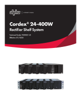
The home screen indicates the realtime status of the panel based on its backlight color.
Backlight color Status indicated Alarm type
Green Normal operation N/A
Orange Warning Minor
Red Alarm Major
5.3 Initial operation
Once all breakers are installed and power is present on the inputs, remove the breaker
compartment door and slide the power switch to the on position. The power switch is located
on the front right side of the SmartSwitch LCD. The LCD turns on and displays the Alpha® logo
followed by the firmware version.
5.3.1 Breaker inventory process
Before the monitoring features of the Matrix C16™ panel can be viewed on a Cordex® HP
controller, a breaker inventory must be taken.
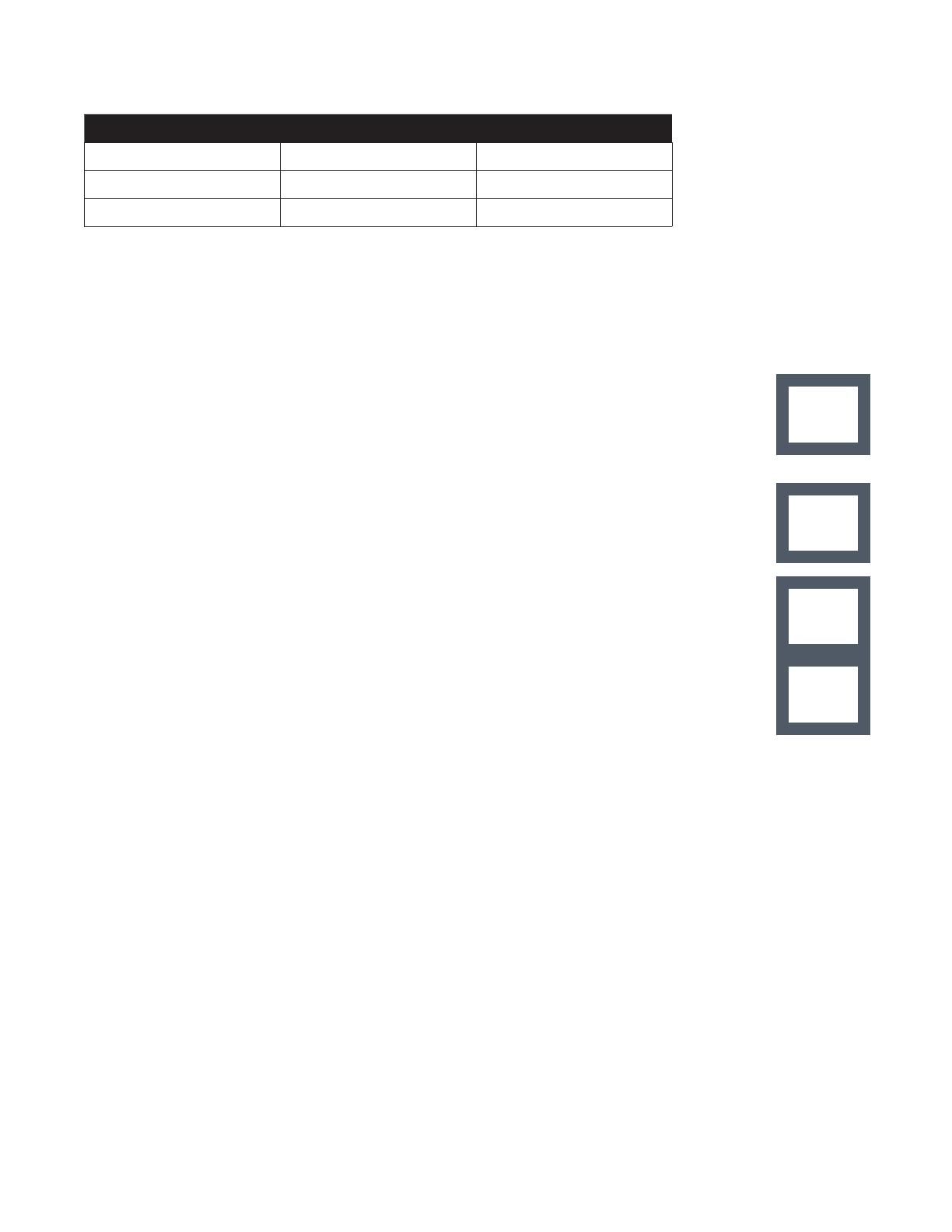
1. Upon first power up, the system prompts TURN ON THE BKRS HOLD 3S.
2. Turn on all breakers to be inventoried. Press and hold the LCD as prompted.
3. The LCD will show the number of breakers installed in the panel. If the number of breakers
displayed is incorrect, check that all installed breakers are fully seated, in the correct
orientation, and turned on.
4. If the number of breakers is correct, press and hold the LCD for three seconds to continue.
5. The LCD shows STORED PRESS TO CONT. Tap the LCD to continue and set the breaker
ampacity.
5.3.2 Setting breaker ampacity
The SmartSwitch LCD prompts SETUP BKR AMPS HOLD 3S.
1. Press and hold the LCD for three seconds to enter the menu to set breaker ampacity.
2. The first breaker in inventory will be displayed, along with its currently set ampacity. If the
ampacity is incorrect, press and hold the LCD for three seconds to enter the menu.
3. Tap the LCD until the correct ampacity is displayed (the display will advance through
standard Slimline breaker ampacities: 1, 3, 5, 10, 15, 20, 25, 30, 35, 40, 45, 50, 55, 60, 65,
70, 80, 90, and 100), then press and hold the LCD for three seconds to save the value.
4. The next breaker in inventory will now be displayed. Repeat steps 1 to 3 for each breaker in
inventory.
5. Once all of the breaker ampacities are set correctly, advance to the screen that says EXIT
HOLD 3 S and press and hold the LCD for three seconds to exit the menu and save the
values.
This completes the initial SmartSwitch setup.
SETUP
BKR INV
HOLD 3 S
TURN ON
THE BKRS
HOLD 3 S
STORED
PRESS TO
CONT.
SETUP
BKR AMPS
HOLD 3 S
19
0921002-J0 Rev A
User Guide Cordex® CXPS-HSS Hyperboost Converter Systems
5.3.3 VIEW BKR LOAD HOLD 3 S
Entering this menu will display voltage, current, and alarm status information for each circuit that
is stored in inventory. When the menu is entered, the first circuit in inventory will be displayed.
Tapping the SmartSwitch LCD will advance to the next circuit in inventory.
5.3.4 SETUP HOLD 3 S (setup menu)
The setup menu is used to configure the SmartSwitch LCD. The system will prompt you with
SETUP HOLD 3 S to enter the menu. This menu is accessed by taping the home screen until
the prompt appears, then pressing and holding the LCD for three seconds.
5.3.5 SETUP BKR INV HOLD 3 S (breaker inventory)
Press and hold the SmartSwitch LCD for three seconds to enter the menu and perform a
breaker inventory. Follow the on-screen prompts to finish inventorying circuits. A breaker
inventory must be performed every time a new circuit is added to the Matrix C16 panel.
5.3.6 SETUP BUS ALMS
Press the LCD for three seconds to access the Bus Alarm Menu.
This menu is used to set the input bus rating to enable the panels over current monitoring
features.
1. To set the bus A ampacity, select the option that displays SETUP BUS A HOLD 3 S. The
LCD will then display HOLD TO EDIT, TAP TO SHIFT. Press the LCD to access the first bus.
2. Three digits will now appear on screen with an arrow under the first digit.
3. To edit a digit, press the LCD for three seconds, then tap to change its value. Hold for three
seconds to save the edits.
4. Repeat these steps for each digit that needs to be edited.
5. Repeat for bus B.
5.3.7 SETUP BKR ALMS
Press the LCD for three seconds to access the Breaker Alarm Menu.
This menu is used to configure the alarm and warning threshold for overcurrent alarms.
The alarm setting is used to set the threshold for the panel’s overcurrent alarm. An alarm
condition will annunciate locally with a red display and an audible alarm. It will also cause a
remote alarm via the Form C dry alarm contact and email alerts via the Ethernet web server.
The warning setting is used to set the threshold for the panel’s overcurrent warning (pre-alarm).
The warning will only annunciate locally.
5.3.8 SETUP VOLT CAL
Press the LCD for three seconds to access the Voltage Calibration Menu.
This menu is used to calibrate displayed bus voltages. Voltage can only be edited if within valid
voltage range.
VIEW BKR
LOAD
HOLD 3 S
SETUP
HOLD 3 S
SETUP
BKR INV
HOLD 3 S
SETUP
BUS ALMS
HOLD 3 S
SETUP
BUS A
HOLD 3 S
SETUP
BKR ALMS
Hold 3 s
  • Page 1 1
  • Page 2 2
  • Page 3 3
  • Page 4 4
  • Page 5 5
  • Page 6 6
  • Page 7 7
  • Page 8 8
  • Page 9 9
  • Page 10 10
  • Page 11 11
  • Page 12 12
  • Page 13 13
  • Page 14 14
  • Page 15 15
  • Page 16 16
  • Page 17 17
  • Page 18 18
  • Page 19 19
  • Page 20 20
  • Page 21 21
  • Page 22 22
  • Page 23 23
  • Page 24 24
  • Page 25 25
  • Page 26 26
  • Page 27 27
  • Page 28 28
  • Page 29 29
  • Page 30 30
  • Page 31 31
  • Page 32 32
  • Page 33 33
  • Page 34 34
  • Page 35 35
  • Page 36 36
  • Page 37 37

Alpha Cordex CXPS-HSS User manual

Type
User manual

Ask a question and I''ll find the answer in the document

Finding information in a document is now easier with AI