Page is loading ...

AE-V812 Sensorless Vector Type Inverter Manual
[1]
Before the words
Thank you for the use of AE-technology CO., LTD of the AE-V812 series inverter.
AE-V812 Sensorless Vector Type Inverter is AE-technology CO., LTD to adopt new ideas
independently developed a series of high performance, low noise, current vector type inverter.
In improving the stability of the added under the condition of simple PLC, practical PI
regulation (with constant pressure water supply function), flexible input / output terminals,
parameter modification, since the identification signal transmission failure, power outages and
stop parameter storage, injection molding machine energy saving control, swing frequency
control, RS485 control, field bus control and a series of practical operation, control function.
For equipment manufacturers and end customers to provide high integration integration
solutions, to reduce the purchase and operating costs, enhance the reliability of the system is of
great help.
In the use of AE-V812 series inverter before, please users and relevant technical personnel
carefully read the instructions, to ensure the correct installation and operating AE-V812 series
inverter, the inverter to play its best performance.
The specification are subject to change, please refer to the latest version, without traffic.
Target readers
The instruction manual for the following staff reading
Inverter installation,Engineering technical personnel,Design personnel.
Book Agreement
Sign Agreement
Inspection Due to the absence of the requested operation, may
cause moderate damage or injuries.
Danger Due to the absence of the requested operation, may result
in death or serious injury.

AE-V812 Sensorless Vector Type Inverter Manual
[2]
—Contents—
Chapter 1 Introduction
1.1 Unpacking Inspection -------------------------------( 5)
1.2 Safety Rules ----------------------------------------------------(5)
1.3 Notes on Usage ------------------------------------------------(8)
1.4 Notes Regarding Disposal------------------------------(11)
Chapter 2 Models and Specifications
2.1 Models --------------------------------------------------------(12)
2.2 Specifications -------------------------------------------------------(13)
2.3 Parts of Inverter ----------------------------------------------(15)
2.4 Dimensions ------------------------------------------------(16)
2.5 Optional Parts-------------------------------------( 18)
Chapter 3 Installation and Wire Connection
3.1 Installation ----------------------------------------( 21)
3.2 Removing and Mounting Front Cover of Inverter ----------(22)
3.3 Wire Connection ----------------------------------------(22)
3.4 Main Circuit Wiring -------------------------------------(23)
3.5 Basic Wiring Diagram ------------------------------(24)
3.6 Control Circuit Terminal Wiring ------------------------(25)
3.7 EMC Installation Instruction -------------------------( 31)
Chapter 4 Running of Inverter
4.1 Running of Inverter -------------------------------------- (34)
4.2 Operation and Using of the Control Panel ----------------(37)
4.3 Inverter power -----------------------------------------(45)

AE-V812 Sensorless Vector Type Inverter Manual
[3]
Chapter5 Function Parameter Table
5.1 Symbol Description --------------------------------------(46)
5.2 Function Code Table ---------------------------------( 46)
Chapter 6 Function Code Description
6.1 Basic running function parameter (P0 Group) -----------(64)
6.2 Frequency Setting Function Parameter (P1 Group) -------(72)
6.3 Start/Brake Function Parameter (P2 Group) -----------(74)
6.4 Auxiliary Running Parameter (P3 Group) -------------(77)
6.5 Terminal Control Function Parameter (P4 Group) -----------(86)
6.6 Protection Function Parameter (P5 Group) ------------(101)
6.7 Fault Record Function Parameter (P6 Group) -----------(105)
6.8 Close Loop Running Control Function Parameter (P7 Group) ---(105)
6.9 Injection Machine Parameter (P7-Z Group) -----------(113)
6.10 PLC Running Parameter (P8 Group) --------------(116)
6.11 Swing Frequency Function Parameter (P9 Group) ---------(121)
6.12 Vector Control Parameter (PA Group) ----------------(125)
6.13 Factory Function Parameter (PF Group) -----------(126)
Chapter 7 Troubleshooting
7.1 Fault Alarm and Troubleshooting -------------( 127)
7.2 Fault Record Serach -----------------------( 1 30)
7.3 Fault Reset -----------------------------------( 131)
Chapter 8 Preservation and Maintenance
8.1 Preservation and Maintenance --------------------(132)
8.2 Periodic Preservation and Maintenance ------------(132)

AE-V812 Sensorless Vector Type Inverter Manual
[4]
8.3 Warranty of Inverter ------------------------------(133)
Chapter 9 Serial Port Communication Protocol of RS485
9.1 Communication Overview ---------------( 134 )
9.2 Communication Protocol Specification -------------(135)
9.3 The ASCII Communication Protocol ------( 136)

AE-V812 Sensorless Vector Type Inverter Manual
[5]
Chapter 1 Introduction
1.1 Unpacking Inspection
Upon unpacking, please confirm the following: Any damage occurred during
transportation; Check whether the model and specifications on the nameplate of
inverter are in accordancewith your order.
If there is any error, please contact us or distributors.
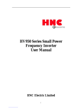
Inverter type description
AE-V812-G1R5/P2R2T4
Fig 1-1 Inverter type description
The model and specifications on the nameplate of inverter on the bottom right of
inverter.
1.2 Safety Rules
Inspection
Inspection
1. Please do not install the damaged inverter, otherwisethere is a
danger of injury.
Inverter series
Motor Power
0R7
0.75 kW
1R5
1.5 kW
030
30.0 kW
450
450.0 kW
Inverter type
G
P
Constanttorque
Fan pump type
4
Input Voltage
T
Three phase
S
Single phase
380 V
2
220 V
Code
Integraned Brake Unit
The cabinet
Standart model
В
С
no

AE-V812 Sensorless Vector Type Inverter Manual
[6]
Installation
Inspection
1. Handling, please hold the bottom of the body, otherwise there
is a danger of a body falling foot injury.
2. Please install the inverter on metal or other nonflammable
material, otherwise there is a danger of fire.
3. Please install cooling fans when two inverters are installed in a
same cabinet, keep the air intake temperature under 40
℃
,
otherwise, there is a danger of fire.
Cable connection and distribution
Danger
1. Wire-connection job can only be done when the mains are cut
off, otherwise, there is a danger of shock or fire.
2. Only qualified personnel can perform wire-connection job,
otherwise, there is a danger of shock or fire.
3. The earth terminal of frequency inverter must be connected to
earth reliably, otherwise, there is a dangerof shock or fire.
(Please use the 3rd grounding method specially for 380V)
4. After connects emergency stop terminal, please make sure it is
effective, otherwise, there is a danger of injury.
(The user is responsible for the connection)
5. Please don’t touch the output terminals, don’t connect the

AE-V812 Sensorless Vector Type Inverter Manual
[7]
output terminals with the shell, don’t short connect the output
terminals, otherwise, there is a danger of shock or short circuit.
Attention
1. Please confirm the mains supply is in accordance with rated
voltage of inverter, otherwise, there is a danger of injury or fire.
2. Please don’t make voltage withstanding test to the inverter. It
may damage the semiconductor and other components.
3. Please connect the braking unit or resistance according to the
wiring diagram; otherwise, there is a danger of fire.
4. Please use screw drivers with appointed moment of force to
tighten the terminals, otherwise, there is a danger of fire.
5. Please don’t connect input mains cable with output terminals of
U/V/W. It may damage the inverter.
6. Please don’t connect shifting capacitor or LC/RC noise filter
with output loop. It may damage the inverter
.
7. Please don’t connect solenoid switch or solenoid contactor with
output loop. When inverter is running with load, the action of
such swith and contactor will cause surge current. It may trigger
over current protection of inverter.
8. Please just disassemble the terminals cover when wiring, don't
disassemble the front cover of inverter. It may damage the
inverter.
Maintenance and inspection

AE-V812 Sensorless Vector Type Inverter Manual
[8]
Danger
1. Please do not touch the control terminals when it is live,
otherwise there is a danger of shock.
2. Please make sure the termnials cover is assembled before power
up. Before diassembling the termnials cover, please make sure
the power is cut off, otherwise, there is a danger of shock.
3. Only qualified personnel can perform the maintenance and
inspection job, otherwise, there is a danger of shock.
Attention
1.
The keyboard, control circuit board, and driver circuit board
were integrated with CMOS circuit. Please be careful when
using. Please don not touch these circuit boards by fingers.
2. Please don’t change the cable connection when power on.
1.3 Notes on Usage
In the use of AE-V812 series inverter, please pay attention to the following points:
1. Constant torque low speed running
When the inverter outputs to a common motor at low speed for a long term, the
output rated torque should be derated due to the worsening radiating effect. If low
speed constant torque long term running is required, then a special variable
frequency motor is needed.

AE-V812 Sensorless Vector Type Inverter Manual
[9]
2. Confirm motor’s insulation
Before usingAE-V812 series inverter, please confirm the motor is insulated;
otherwise, the equipment may be damaged. Please confirm motor’s insulation termly
when motor is working under bad condition.
3. Negative torque load
To some application situation such as lifting load, negative torque load may occur.
Braking unit and resistor should be connected with inverter, or over current or over
voltage fault may happen.
4. The mechanical resonance point of load
The inverter may encounter the mechanical resonance point of load within certain
output frequency range. Jump frequencies have to be set to avoid it.
5. Capacitor and varistor
Because the inverter outputs PWM pulse wave, capacitor and varistor should not be
connected with the output terminals of the inverter, or the inverter may trip or
components may be damaged,as shown in Fig.1-3.
Fig. 1-3 Capacitor connection with inverter output prohibited
6. Motor derating
When basic frequency is set to be lower than rated frequency, motor derating is
necessary in order to avoid motor overheating.

AE-V812 Sensorless Vector Type Inverter Manual
[10]
7. Running at frequency above 50Hz
If running at frequency above 50Hz, besides the increment of vibration and noise,
the ranges of running speed of motor shaft and mechanical device have to be
guaranteed. Be sure to make an enquiry first.
8. The electro-thermal protective value of motor
If the applicable motor is selected as per requirements, the inverter can perform the
thermal protection to the motor. If the ratings of applied motor are not in compliance
with the inverter, be sure to adjust the protective value to guarantee the safe running
of motor.
9. Altitude and derating
When the altitude is higher than 1000m, the cooling effect of inverter is deteriorated
because of the rareness of air, derating must be considered.
80%
90%
100%
1000 2000 3000 4000
I
out
£¨Ã×£©
Fig.1-4 indicates the relationship between the altitude and rated current of frequency inverter.
10. On the level of protection
AE-V812 Inverter protection grade IP20 is in the selection of state display unit or
the keyboard case reach.
(
m)

AE-V812 Sensorless Vector Type Inverter Manual
[11]
1.4
Notes Regarding Disposal
When you dispose frequency inverter, pay attention to:
The capacitors in the main circuits may explode when they are burned. Poisonous
gas may be generated when front panel is burned.
Please dispose the inverter as industrial rubbish.

AE-V812 Sensorless Vector Type Inverter Manual
[12]
Chapter 2 Models and Specifications
2.1 Models
AE-V812 series inverter has 2 kinds of voltage levels, 220V and 380V. The
range of applicable motor is from 0.4KW to 315KW. Models of VCD1000 series are
shown in Table 2-1.
Table 2-1. Models description
Voltage level
Models
Rated
capacity
(
KVA
)
Ratedoutput
current
(
A)
Applicable
motor(KW)
380V
Three phase
AE-L0R75S2
1.5 4.7 0.75
AE-L1R5S2
2.8 7.5 1.5
AE-L2R2S2
3.8 10.0 2.2
AE-V812-G1R5/P2R2T4
2.5 4.0 / 6.0 1.5 / 2.2
AE-V812-G2R2/P3R7T4
3.0 6.0 / 9.6 2.2 / 3.7
AE-V812-G3R7/P5R5T4
5.9 9.6 / 14.0 3.7 / 5.5
AE-V812-G5R5/P7R5T4
8.5 14.0 / 17.0 5.5 / 7.5
AE-V812-G7R5/P11T4
11 17.0 / 25 7.5 / 11
AE-V812-G11/P15T4
17 25 / 32 11 / 15
AE-V812-G15/P18T4
21.7 32 / 39 15 / 18.5
AE-V812-G18/P22T4
25.7 39 /45 18.5 / 22
AE-V812-G22/P30T4
29.6 45 / 60 22 / 30
AE-V812-G30/P37T4
39.5 60 / 75 30 / 37
AE-V812-G37/P45T4
49.4 75 / 91 37 / 45
AE-V812-G45/P55T4
60 91 / 112 45 / 55
AE-V812-G55/P75T4
73.7 112 / 150 55 / 75
AE-V812-G75/P90T4
99 150 / 176 75 / 90
AE-V812-G90/P110T4
116 176 / 210 90 / 110
AE-V812-G110/P132T4
138 210 / 253 110 / 132
AE-V812-G132/P160T4C
167 253 / 304 132 / 160
AE-V812-G160/P185T4C
200 304 / 355 160 / 187
AE-V812-G185/P200T4C
234 355 / 377 187 / 200

AE-V812 Sensorless Vector Type Inverter Manual
[13]
AE-V812-G200/P220T4C
248 377 / 426 200 / 220
380V
AE-V812-G220/P250T4C
280 426 / 474 220 / 250
Three phase
AE-V812-G250/P280T4C
318 474 / 520 250 / 280
AE-V812-G280/P315T4C
342
520 / 600
280 / 315
AE-V812-G315/P355T4C
390 600 / 660 315 / 355
AE-V812-G355/P400T4C
435 660 / 750 355 / 400
AE-V812-G400T4C
493 750 400
AE-V812-G450T4C
560 850 450
2.2 Specifications
Items Specifications
Input
Ratedvoltage/Frequency
Singlephase220V, three phase 200V, three phase 380V;50Hz/60Hz
Range
Voltage: ±20% voltage unbalancerate:<3%; frequency: ±25%
Output
Rated voltage
0
~
200V/220V/380V
Frequency range
0Hz
~
500Hz
Frequency r esolution
0.01Hz
Overload ability
150% ratedcurrent for1minute, 180% rated current for3 seconds
Control
function
Modulation modes
Optimized space voltage vector SVPWM modulation
Control mode
Sensorlessvector control (withoptimallowfrequency deadtime compensation)
Frequency precision
Digital setting: Thehighestfrequency×± 0.01% Analogsetting:Thehighestfrequency
×±0.2%
Frequency resolution
Digital setting: 0.01Hz; Analog setting:The highest frequency× 0.1%
Start frequency
0.40Hz
~
20.00Hz
Torque boost
Auto torque boost, manual torque boost 0.1%~30.0%
V/F curve
Fiveways: constant torque V/F curve, 1 kindof userdefined
V/Fcurve ,3 kindsof downtorque curve(2.0/1.7/1.2times the power)
Acc./Dec. curve
Two ways: linear Acc./Dec.,S-curveAcc./Dec.;7 kinds of Acc./Dec. time,
time unit(minute/second) optional, max.Time: 6000 minutes.
DC braking
DC braking start frequency:0~15.00Hz
braking time:0~60.0秒 braking current:0~80%
Energy consuming braking
Energy consuming braking unit built-in,external braking resistor can be

AE-V812 Sensorless Vector Type Inverter Manual
[14]
Jog running
Jogfrequency range:0.1Hz~50.00Hz, JOGAcc./Dec. time: 0.1~60.0s
PI built-in
Easily constitute a close loop control system
Multi-stage speed
running
Multi-stage speed running available through built-in PLC or
controlterminals
Textile swing frequency
Swing frequency availablewith preset and centre frequencyadjustable
Auto voltage regulation
Whenthe grid voltagechanges, tomaintain constantoutputvoltage
Auto energy saving running
Saving energy byauto optimizing V/F curve according tothe load
Autocurrentlimitting
Auto current limitting to prevent frequent overcurrent fault trip
Fixed-lengthcontrol
Inverter stops when reaches the pr eset length
Communication
RS485 standard communication port available, support MODBUS communication protocol of ASCII and
RTU, master-slave multi-machine interaction function available
Running
function
Running command
channel
Control panel : control terminal :serial port :3 channels switchable
Frequency
setting channel
Controlpanel potentiometer :
▲
▲、▼control panelkeys:;
functioncodedigital: serialport : terminal up/down:
analog voltage: analogcurrent: pulse:
combination setting:all channelsswitchable
Switch input channel
FWD/REVcommand: 8channels programmable switch inputs, 35kinds of
function can be set separately
Analog input channel
4~20mA: 0-10V: 2 optional analog inputs
Analog output channel
4~20mA or 0~10V optional, setting frequency and output
frequency ,etc. can be output
Switch/pulseout
put channel
Programmable opencollector output:relayoutput :0~20KHz pulse output:
Control
panel
LED digital display
Displaysettingfrequency,outputvoltage, output current, etc.
External meter display
Display output frequency, output current, output voltage, etc.
Key lock
All the keys can be locked
Parameter copy
Function code parameters are able to be copyed between
inverters when useremote control panel
。
Protection function
Overcurrentprotection:overvoltageprotection:undervoltageprotection:overheating
protection:overloadprotection,etc.
Optionalparts
Braking unit:remote control panel:cable: panelmountingfeet, etc.
Environment
Indoors, freefromdirect sunlight,dust, corrosivegas, oilmist,steam,
waterdropor salt, etc

AE-V812 Sensorless Vector Type Inverter Manual
[15]
Environ
ment
Altitude
Lower than 1000m (derating is necessary above 1000m)
Ambient temperature
-
10
℃~+
40
℃
Humidity
<90%RH, no condensation
Vibration
Lower than 5.9m/s (0.6g)
Storage temperature
-
20
℃~+
60
℃
Structur
e
Protection level
IP20
(
In the selection of state display unit or the keyboard state
)
Cooling
Forced air cooling
Installation
Wall mounted
2.3 Parts of Inverter

AE-V812 Sensorless Vector Type Inverter Manual
[16]
2.4 Dimensions
H
H1
H2
W
W1
D
D2
1
d
D1
D2
D
W
W1
H2
H1
H
d
(a)、 Inverters below 2.2 KW (b)、 Inverters from 3.7 KW to 160 KW
Table 2-2 Dimensions (mm)
Type Number W W1 H H1 H2 D D1 D2 d
AE-L0R75S2
85 70 155 144 142 121.7 112 70 5
AE-L1R5S2
AE-L2R2S2
AE-V812-G2
R2/P3R7T4
118 108 230 220 210 153 164 100 5
AE-V812-G3
R7/P5R5T4
AE-V812-G5
R5/P7R5T4
216 202 300 290 300 212 217 110 6
AE-V812-G7
R5/P11T4
AE-V812-G1
1/P15T4
245 186 350 334 310 215 220 130 10

AE-V812 Sensorless Vector Type Inverter Manual
[17]
AE-V812-G1
5/P18T4
AE-V812-G1
8/P22T4
291 200 520 500 477 266 280 170 10
AE-V812-G2
2/P30T4
AE-V812-G3
0/P37T4
AE-V812-G3
7/P45T4
348 300 587 563 544 293 308 170 10
AE-V812-G4
5/P55T4
AE-V812-G5
5/P75T4
395 278 618 598 578 300 310 250 10
AE-V812-G7
5/P90T4
AE-V812-G9
0/P110T4
482
282
652
632
612
310
320
260
10
AE-V812-G1
10/P132T4
AE-V812-G1
32/P160T4C
AE-V812-G1
60/P185T4C
600
1440
400
AE-V812-G1
85/P200T4C

AE-V812 Sensorless Vector Type Inverter Manual
[18]
AE-V812-G2
00/P220T4C
AE-V812-G2
20/P250T4C
2.5 Optional Parts:
The following options, if necessary, please to my company ordered another。
2.5.1 Remote control panel
RS 485 communicationis applied between remote control panel and inverter which
are connectedby a 4-core cable via RJ45 network port.
The maximum connection distance is 500 M.The inverter supportslocal control
panel and remote control panel used at the same time, no priority, both can control
the inverter . HotPlugIn for remotecontrol panel is available.
The following functionsare available by using remote control panel:
(1) Control slave inverter to run, stop, jog run, fault reset, chang setting frequency,
change function parameters and running direction.
(2) Monitor slave inverter’s running frequency , setting frequency , output voltage,
output current, busbar voltage, etc.
2.5.2 Communication cable for remote control panel
Type:AE-V812-LAN0020 (2.0m)
Standard options:1m, 2m, 5m, 10m, 20m,More than 20m can be customized.
For the remote keyboard and inverter host connection
2.5.3 Fieldbus Adaptor
The inverter canbe connected into MODBUS fieldbus networkvia adaptor as a slave
station in the network.
The function asfollow:
(1) To send command to inverter such as start, stop, jog running, etc.

AE-V812 Sensorless Vector Type Inverter Manual
[19]
(2) To send speed or frequency signal to inverter.
(3) To read status from inverter.
(4) To fault reset for the inverter.
Please refer to Chapter 9 forcommunication protocol
2.5.4
Braking Resistors
AE-V812 series inverters under15KW have built-in braking units.If energy
consuming braking is needed. Please choose braking resistors accordingto Table
2-3. The wire connection of braking resistors are shown in Fig. 2-2.
Fig.2-2 The wire connection of braking resistors
Table 2-3 Braking resistors selection table
Model
Applicable motor (KW)
Resistance (Ω )
Resistance power (W)
AE-V812-2S0004G 0.4 200 100
AE-V812-2S0007G 0.75 150 200
AE-V812-2S0015G 1.5 100 400
AE-V812-2S0022G 2.2 70 500
AE-V812-4T0007G 0.75 300 400
AE-V812-4T0015G 1.5 300 400

AE-V812 Sensorless Vector Type Inverter Manual
[20]
AE-V812-4T0022G 2.2 200 500
AE-V812-4T0037G 4.0 200 500
AE-V812-4T0055G 5.5 30 1000
AE-V812-4T0075G 7.5 30 1000
/