
PREFACE
Thanks for choosing A510 series heavy-duty closed-loop vector frequency inverter produced by
Shenzhen Sunfar Electric Technologies Co., Ltd.
This Manual is the operating manual for A510 series closed-loop vector frequency inverter. It provides
all relevant instructions and precautions for installation, wiring, functional parameters, daily care and
maintenance, fault diagnosis and troubleshooting of A510 series inverter.
In order to use this series of inverters correctly, guarantee product's best performance whilst ensuring
the safety of users and equipment, be sure to read this manual carefully before using A510 series
inverters. Improper use may cause malfunction of the drive, reduce its service life and damage other
equipments and lead to personal injury and death, etc
A user manual is provided with each Variable frequency Drive. Please keep it in a convenient location
so it can be referred to for installation and maintenance. Owing to the constant improvement of
products, the data within future versions of this manual may be changed without further notice.
A510 Series Heavy-Duty Closed-Loop Vector Inverter User Manual
Version: V1.1
Revision Date: July 2014
This Manual is applicable to V6005 and above programs.

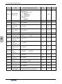
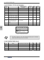
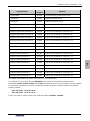
CATALOG
1. PRODUCT CONFIRMATION AND OPERATION CAUTIONS ...................................................................
1.1 PRODUCT CONFIRMATION ...........................................................................................................
1.1.1 CONFIRMATION OF FREQUENCY INVERTER BODY AND ACCESSORIES ..................
1.1.2 NAMEPLATE OF FREQUENCY INVERTER .......................................................................
1.2 SAFETY CAUTIONS ........................................................................................................................
1.2.1 NOTICES DURING INSTALLATION ....................................................................................
1.2.2 SAFETY CAUTION FOR WIRING .......................................................................................
1.2.3 SAFETY CAUTION FOR RUNNING OPERATION ..............................................................
1.2.4 SAFETY CAUTION FOR MAINTENANCE CHECK .............................................................
1.3 KNOWLEDGE ON OPERATION ......................................................................................................
1.3.1 APPLICATION KNOWLEDGE OF DRIVING GENERAL MOTOR .......................................
1.3.2 APPLICATION KNOWLEDGE OF DRIVING SPECIAL MOTOR .........................................
1.3.3 AMBIENT ENVIRONMENT ..................................................................................................
1.3.4 CONNECTION KNOWLEDGE OF PERIPHERAL EQUIPMENT ........................................
1.3.5 TRANSPORTATION AND STORAGE ..................................................................................
1.4 ABANDON CAUTION .......................................................................................................................
2. PRODUCTION INTRODUCTION ................................................................................................................
2.1 INVERTER MODEL ..........................................................................................................................
2.2 PRODUCT APPEARANCE ..............................................................................................................
2.3 MODEL TABLE ................................................................................................................................
2.4 PRODUCT TECHNICAL INDEX AND SPECIFICATIONS ...............................................................
3. INSTALLATION OF FREQUENCY INVERTER ..........................................................................................
3.1 INSTALLATION OF FREQUENCY INVERTER ...............................................................................
3.1.1 MOUNTING SURFACE........................................................................................................
3.1.2 INSTALLATION SPACE .......................................................................................................
3.1.3 MULTIPLE INSTALLATIONS ...............................................................................................
3.2 SIZE AND ASSEMBLY OF OPERATION PANEL............................................................................
3.2.1 DISASSEMBLY ....................................................................................................................
3.2.2 INSTALLATION ....................................................................................................................
3.2.3 EXTENSION OF EXTERNAL CONNECTION .....................................................................
3.3 DISASSEMBLY OF TERMINAL COVER .........................................................................................
3.3.1 DISASSEMBLY AND INSTALLATION OF PLASTIC COVER PLAT ....................................
1
1
1
1
1
2
2
3
3
3
3
4
4
4
4
4
5
5
5
6
7
11
11
11
11
12
12
13
13
13
14
14

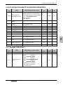
3.3.2 DISASSEMBLY AND INSTALLATION OF SHEET-METAL COVER PLATE ........................
3.4 INSTALLATION SIZE OF PANEL ....................................................................................................
3.5 DISASSEMBLY AND INSTALLATION OF EXPANSION CARD ......................................................
3.6 INSTALLATION SIZE OF FREQUENCY INVERTER ......................................................................
4. WIRING OF FREQUENCY INVERTER .......................................................................................................
4.1 CAUTIONS OF WIRING ...................................................................................................................
4.2 CONNECTION OF OPTIONAL FITTINGS AND FREQUENCY INVERTER ...................................
4.3 WIRING OF STANDARD INTERFACE CARD TERMINAL..............................................................
4.3.1 WIRING OF STANDARD INTERFACE CARD TERMINAL CON1 AND CON2 ..................
4.3.2 FUNCTION DESCRIPTION OF CONTROL TERMINAL ....................................................
4.4 WIRING OF MAJOR LOOP TERMINAL ..........................................................................................
4.4.1 TERMINAL FUNCTIONS ....................................................................................................
4.4.2 WIRING OF MAJOR LOOP TERMINAL AND TERMINAL BLOCKS ..................................
4.5 WIRING CONNECTION OF BASIC OPERATION ...........................................................................
5. OPERATION AND SIMPLE RUNNING OF FREQUENCY INVERTER ......................................................
5.1 BASIC FUNCTION OF PANEL ........................................................................................................
5.1.1 DESCRIPTION OF OPERATING PANEL ............................................................................
5.2 BASIC FUNCTIONS AND OPERATING METHODS OF PANEL ....................................................
5.2.1 BASIC FUNCTIONS OF PANEL ..........................................................................................
5.2.2 OPERATING METHODS OF PANEL ...................................................................................
5.3 SIMPLE RUNNING OF FREQUENCY INVERTER ..........................................................................
5.3.1 OPERATION PROCESS ......................................................................................................
5.3.2 INITIAL SETTING OF FREQUENCY INVERTER ................................................................
5.3.3 SIMPLE OPERATION ..........................................................................................................
6. FUNCTIONAL PARAMETER TABLE .........................................................................................................
6.1 EXPLANATIONS ..............................................................................................................................
6.2 FUNCTION TABLE ...........................................................................................................................
6.2.1 SYSTEM MANAGEMENT PARAMETER ...........................................................................
6.2.2 SELECTION OF RUNNING COMMANDS .........................................................................
6.2.3 FREQUENCY SETTINGS ...................................................................................................
6.2.4 CONTROL COMMAND SOURCE ......................................................................................
6.2.5 START AND STOP ..............................................................................................................
6.2.6 ACCELERATION AND DECELERATION PARAMETERS ..................................................
6.2.7 CARRIER FREQUENCY ....................................................................................................
6.2.8 V/F PARAMETERS AND OVERLOAD PROTECTION FOR MOTOR 1 .............................
15
15
16
17
19
19
20
22
22
22
24
24
25
26
27
27
27
29
29
31
34
34
37
38
40
40
40
40
43
44
45
45
47
47
48

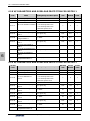
6.2.9 V/F PARAMETERS AND OVERLOAD PROTECTION FOR MOTOR 2 .............................
6.2.10 STEADY RUNNING ..........................................................................................................
6.2.11 PARAMETERS OF MOTOR 1...........................................................................................
6.2.12 VECTOR PARAMETERS OF MOTOR 2 ..........................................................................
6.2.13 PARAMETER MEASUREMENT AND PRE-EXCITATION ................................................
6.2.14 MULTIFUNCTIONAL INPUT TERMINAL ..........................................................................
6.2.15 MULTIFUNCTIONAL OUTPUT TERMINAL ......................................................................
6.2.18 ANALOG INPUT................................................................................................................
6.2.19 ANALOG INPUT CURVE CORRECTION .........................................................................
6.2.20 ANALOG OUTPUT............................................................................................................
6.2.21 ANALOG INPUT POWER FAILURE DETECTION ...........................................................
6.2.22 SIMULATED ANALOG INPUT (PSEUDO INPUT) ............................................................
6.2.23 SKIPPING FREQUENCY .................................................................................................
6.2.24 BUILT-IN AUXILIARY TIMER ............................................................................................
6.2.25 BUILT-IN AUXILIARY COUNTER .....................................................................................
6.2.26 AUXILIARY FUNCTIONS ..................................................................................................
6.2.27 MOTOR TEMPERATURE DETECTION ...........................................................................
6.2.28 MULTI-STAGE FREQUENCY SETTING ..........................................................................
6.2.29 SIMPLE PROGRAMMABLE MULTI-STAGE OPERATION ..............................................
6.2.30 SWING FREQUENCY OPERATION ................................................................................
6.2.31 STANDARD PID (4ms CONTROL CYCLE) ......................................................................
6.2.32 STANDARD PID MULTI-STAGE SETTING ......................................................................
6.2.34 REVOLUTION SETTING AND FEEDBACK .....................................................................
6.2.35 REVOLUTION CLOSED-LOOP PARAMETER .................................................................
6.2.36 PROTECTION PARAMETER ...........................................................................................
6.2.37 TORQUE CONTROL ........................................................................................................
6.2.38 HIGH SPEED PID (RUNNING CYCLE: 1ms) ...................................................................
6.2.39 HIGH SPEED PID CONTROLLER PARAMETER SELECTION .......................................
6.2.40 MODBUS FIELDBUS (STANDARD EXPANSION CARD CONFIGURATION) .................
6.2.41 MAPPING ACCESS PARAMETER ...................................................................................
6.2.42 COMMUNICATION LINKAGE SYNCHRONOUS CONTROL...........................................
6.2.43 PARAMETERS OF EXPANSION COMMUNICATION MODULE .....................................
6.2.44 EXPANSION MULTIFUNCTIONAL INPUT TERMINAL (EDI1~ EDI8)/ EFFECTIVE
AFTER CONNECTING EXPANDING ACCESSORIES ...............................................................
6.2.45 EXPANSION MULTIFUNCTIONAL INPUT TERMINAL ....................................................
48
49
50
51
52
52
53
54
55
55
56
57
57
58
59
60
62
62
63
64
65
68
68
70
71
71
73
74
75
76
77
78
78
79

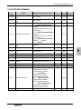
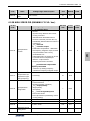
6.2.46 ZERO-SPEED TORQUE AND POSITION CONTROL .....................................................
6.2.47 SIMULATED INPUT AND OUTPUT ..................................................................................
6.2.48 PROTECTION FUNCTION CONFIGURATION PARAMETER .........................................
6.2.49 CORRECTION PARAMETER ...........................................................................................
6.2.50 SPECIAL FUNCTIONAL PARAMETERS ..........................................................................
6.2.51 OTHER CONFIGURATION PARAMETERS .....................................................................
6.2.52 HISTORICAL FAULT RECORDING ..................................................................................
6.2.53 OPERATION STATUS AT THE LAST FAULT ...................................................................
6.2.54 BASIC STATUS PARAMETER..........................................................................................
6.2.55 AUXILIARY STATUS PARAMETER ..................................................................................
6.2.56 MODBUS FIELDBUS STATUS PARAMETER ..................................................................
6.2.57 TERMINAL STATUS AND VARIABLE ...............................................................................
6.2.58 COUNTER TIMER VALUE ................................................................................................
6.2.59 SPINDLE CONTROL AND SCALE POSITIONING STATUS PARAMETER .....................
6.2.60 EQUIPMENT INFORMATION ...........................................................................................
TABLE 1: COMPARISON TABLE OF MULTIFUNCTIONAL TERMINAL (DI/EDI/SDI)
FUNCTIONS ................................................................................................................................
TABLE 2: COMPARISON TABLE OF MULTIFUNCTIONAL OUTPUT TERMINAL
(DO/EDO/SDO) VARIABLES .......................................................................................................
TABLE 3: COMPARISON TABLE OF MONITOR VARIABLES ....................................................
7. DETAILED FUNCTION INSTRUCTIONS ...................................................................................................
7.1 SYSTEM MANAGEMENT (GROUP F0.0) .......................................................................................
7.2 RUNNING COMMAND SELECTION (GROUP F0.1) .......................................................................
7.3 FREQUENCY SETUP (GROUP F0.2) .............................................................................................
7.4 CONTROL COMMAND SOURCE (GROUP F0.3) ...........................................................................
7.5 START AND STOP (GROUP F0.4) ..................................................................................................
7.6 ACCELERATION AND DECELERATION CHARACTERISTICS (GROUP F1.0) ............................
7.7 CARRIER FREQUENCY (GROUP F1.1) .........................................................................................
7.8 V/F PARAMETERS AND OVERLOAD PROTECTION (MOTOR 1) (GROUP F1.2) .......................
7.9 STEADY RUNNING (GROUP F1.4) .................................................................................................
7.10 VECTOR PARAMETERS (GROUP F2.0) ......................................................................................
7.11 MOTOR PARAMETER TUNING (GROUP F2.2) ...........................................................................
7.12 MULTIFUNCTIONAL INPUT TERMINAL (GROUP F3.0) ..............................................................
7.13 MULTIFUNCTIONAL OUTPUT TERMINAL (GROUP F3.1) ..........................................................
7.14 PULSE INPUT (GROUP F3.2) .......................................................................................................
79
81
82
84
84
85
86
86
87
89
89
90
90
91
91
92
92
94
96
96
104
110
114
115
121
123
124
125
129
131
132
141
144

7.15 PULSE OUTPUT (GROUP F3.3) ...................................................................................................
7.16 ANALOG INPUT (GROUP F4.0) ....................................................................................................
7.17 ANALOG INPUT CURVE CORRECTION (GROUP F4.1) .............................................................
7.18 ANALOG OUTPUT (GROUP F4.2) ................................................................................................
7.19 ANALOG INPUT WIRE-BREAK DETECTION (GROUP F4.3) ......................................................
7.20 HOPPING FREQUENCY (GROUP F5.0) .......................................................................................
7.21 BUILT-IN AUXILIARY TIMER (GROUP F5.1) ................................................................................
7.21.1 BASIC FUNCTIONS OF THE TIMER ...............................................................................
7.21.2 TRIGGER AND GATE CONTROL FUNCTION SETTING OF TIMER ..............................
7.21.3 CLOCK CONCATENATION FUNCTION SETTING OF TIMER ........................................
7.21.4 CONCATENATION TRIGGER FUNCTION SETTING OF TIMER ....................................
7.22 BUILT-IN AUXILIARY COUNTER (GROUP F5.2) .........................................................................
7.23 AUXILIARY FUNCTIONS (GROUP F5.3) ......................................................................................
7.24 MOTOR TEMPERATURE DETECTION (GROUP F5.4) ...............................................................
7.25 MULTI-STAGE FREQUENCY SETTING (GROUP F6.0) ..............................................................
7.26 SIMPLE PROGRAMMABLE MULTI-STAGE OPERATION (GROUP F6.1) ..................................
7.27 SWING FREQUENCY OPERATION (GROUP F6.2) .....................................................................
7.28 PROCESS PID (4ms CONTROL CYCLE) (GROUP F7.0) ............................................................
7.29 PROCESS PID MULTI-STAGE SETTING (GROUP F7.1) ............................................................
7.30 PROCESS PID SLEEPING FUNCTION (GROUP F7.2)................................................................
7.31 REVOLUTION SETTING AND FEEDBACK (GROUP F8.0) ..........................................................
7.32 REVOLUTION CLOSED-LOOP PARAMETER (GROUP F8.1) .....................................................
7.33 PROTECTIVE PARAMETERS (GROUP F8.2) ..............................................................................
7.34 TORQUE CONTROL (GROUP F8.3) .............................................................................................
7.35 COMPENSATION PID (1ms CONTROL CYCLE) (GROUP F9.0) .................................................
7.36 PARAMETER SELECTION OF COMPENSATION PID CONTROLLER (GROUP F9.1) ..............
7.37 MODBUS FIELDBUS (GROUP FA.0) ............................................................................................
7.38 MAPPING PARAMETER ACCESS (GROUP FA.1).......................................................................
7.39 COMMUNICATION LINKAGE SYNCHRONOUS CONTROL (GROUP FA.2) ..............................
7.40 EXPANSION MULTIFUNCTIONAL INPUT TERMINAL (GROUP FB.0) .......................................
7.41 EXPANSION MULTIFUNCTIONAL INPUT TERMINAL (GROUP FB.1) .......................................
7.44 PROTECTING FUNCTION CONFIGURATION PARAMETERS (GROUP FF.1) ..........................
7.45 CORRECTION PARAMETERS (GROUP FF.2).............................................................................
7.46 SPECIAL FUNCTIONAL PARAMETERS (GROUP FF.3) ..............................................................
7.47 OTHER CONFIGURATION PARAMETERS (GROUP FF.4) .........................................................
145
146
147
147
149
149
150
150
151
151
151
152
152
156
158
162
162
166
170
170
170
173
175
176
178
178
180
180
182
183
183
187
188
190
190

8. WARNING, ALARM DIAGNOSIS AND COUNTER MEASURES ..............................................................
8.1 TROUBLESHOOTING WITH WARNING OR ALARM DISPLAY .....................................................
8.1.1 ALARM DISPLAY AND TROUBLESHOOTING ...................................................................
8.1.2 WARNING DISPLAY AND TROUBLESHOOTING ..............................................................
8.2 ABNORMAL OPERATION WITHOUT PROMPTS AND THE SOLUTIONS ....................................
8.3 FAILURES IN SETTING OPERATION OF FREQUENCY INVERTER ............................................
1. NO DISPLAY IN THE OPERATION PANEL ..............................................................................
2. THE FUNCTION CODE CAN NOT BE CHANGED ..................................................................
8.4 INQUIRY FOR FAILURE RECORD .................................................................................................
8.5 RESET OF WARNING OR ALARM FAILURE .................................................................................
9. MAINTENANCE ..........................................................................................................................................
9.1 ROUTINE MAINTENANCE ..............................................................................................................
9.2 INSPECTION AND DISPLACEMENT OF THE VULNERABLE COMPONENTS ............................
9.2.1 FILTER CAPACITOR ...........................................................................................................
9.2.2 COOLING FAN ....................................................................................................................
9.3 STORAGE ........................................................................................................................................
9.4 WARRANTY .....................................................................................................................................
10. EXAMPLE OF USAGE ..............................................................................................................................
10.1 ENERGY-SAVING TRANSFORMATION OF ESCALATORS .......................................................
10.1.1 SCHEME DESCRIPTION ..................................................................................................
10.1.2 WIRING DIAGRAM ............................................................................................................
10.2 MAKE SIMPLE TENSION CLOSED-LOOP CONTROL WITH OFFSET PID ................................
10.2.1 DIAGRAM OF CONSTANT TENSION CONTROL ............................................................
10.2.2 DIAGRAM OF CONTROL STRUCTURE ...........................................................................
10.2.3 CONFIGURATION .............................................................................................................
10.2.4 WIRING DIAGRAM ............................................................................................................
10.3 APPLICATION IN MECHANICAL FACTORY ................................................................................
10.3.1 CONFIGURATION .............................................................................................................
10.3.2 EXTERNAL CIRCUIT WIRING DIAGRAM ........................................................................
10.4 MULTI-PID SETUP, MULTI-PART PID SETUP, FORM A MULTI-STEP PIDSETUP (TO
REDUCE OVERSTRIKE) .......................................................................................................................
10.4.1 PARAMETER SETUP ........................................................................................................
10.4.2 DIAGRAM OF STEP PID VALUE GIVEN ...........................................................................
11. DESCRIPTION OF COMMUNICATION PROTOCOL ...............................................................................
11.1 MODBUS PROTOCOL DESCRIPTION .........................................................................................
192
192
192
197
199
202
202
202
202
204
205
205
206
206
206
207
207
208
208
208
209
209
210
210
210
211
212
212
212
213
213
213
214
214

11.1.1 PROTOCOL OVERVIEW ...................................................................................................
11.1.2 INTERFACE AND TRANSMISSION METHOD ..................................................................
11.1.3 DATA STRUCTURE ...........................................................................................................
11.1.4 PARAMETER CONFIGURATION FOR FREQUENCY INVERTERS .................................
11.1.5 BRIEF INTRODUCTION OF FUNCTIONS ........................................................................
11.1.6 ACCESS ADDRESS SUMMARY .......................................................................................
11.1.7 DETAILED MODBUS ADDRESS-FINDING DISTRIBUTION .............................................
11.1.8 EXAMPLES ................................................................................................
12. ACCESSORIES .........................................................................................................................................
12.1 BRAKING UNIT ..............................................................................................................................
12.1.1 MODEL OF BRAKE UNIT ..................................................................................................
12.1.2 MODEL SELECTION FOR BRAKE RESISTANCE ...........................................................
12.1.3 APPEARANCE OF BRAKE UNIT ......................................................................................
12.1.4 INSTALLATION SIZE OF BRAKE UNIT ............................................................................
12.1.5 SINGLE BRAKE UNIT AND INVERTER REFERENCE WIRING SKETCH .......................
12.1.6 WIRING PRECAUTIONS ...................................................................................................
12.2 I/O INTERFACE CARD (STANDARD TYPE: DEC5I0AS, PN: 050M008005000) .........................
12.2.1 OUTSIDE VIEW OF I/O STANDARD INTERFACE CARD ................................................
12.2.2 FUNCTIONS OF I/O STANDARD INTERFACE CARD TERMINAL ..................................
12.2.3 ASSEMBY OF STANDARD INTERFACE CARD ...............................................................
12.2.4 WIRING FOR STANDARD INTERFACE CARD ................................................................
12.3 I/O EXPANSION CARD STANDARD .............................................................................................
12.3.1 I/O EXPANSION CARD STANDARD DIMENSIONS .........................................................
12.3.2 FUNCTIONS OF I/O STANDARD INTERFACE CARD TERMINAL ..................................
12.4 PG FEEDBACK CARD (STANDARD TYPE DEC3PG12AA, PN: 050M009012001) ....................
12.4.1 OUTSIDE VIEW OF PG FEEDBACK CARD (STANDARD) ..............................................
12.4.2 FUNCTIONS OF PG CARD (STANDARD) TERMINAL .....................................................
12.5 DESCRIPTION OF LED OPERATING PANEL ..............................................................................
12.5.1 OUTSIDE VIEW OF LED OPERATING PANEL ................................................................
12.5.2 OPERATING INSTRUCTIONS OF LED OPERATING PANEL ..........................................
214
214
214
215
215
216
216
220
222
222
222
222
223
223
224
224
225
225
225
226
226
227
227
227
228
228
228
229
229
229

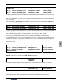
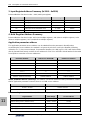
Product Confirmation And Operation Cautions 1
A510 Series Heavy-Duty Closed-Loop Vector Inverter User Manual
1
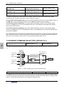
1. PRODUCT CONFIRMATION AND OPERATION
CAUTIONS
1.1 PRODUCT CONFIRMATION
This unit has been subject to strict packaging before release from factory. However, in consideration of
various factors during transportation, please check the outer packing carefully to see if there is any damage
hat may have occurred during transportation; please check the label on the outer packing, and confirm the
model and specifications are in accordance with your order. If any damage or discrepancy is found, please
contact the supplier promptly for a solution.
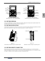
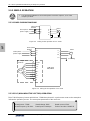
1.1.1 CONFIRMATION OF FREQUENCY INVERTER AND ACCESSORIES
Confirm the frequency inverter nameplate details, and check for any damage that may have occurred
during the transit, if any parts and components have sustained damage, and that the frequency inverter is
complete with the following accessories:
z Operation instruction;
z Certification;
z Product list;
z Other ordered accessories;
If there is any omission or damage, please contact the supplier promptly for solution.
1.1.2 NAMEPLATE OF FREQUENCY INVERTER
On the frequency inverter, there is a nameplate marked with model, rated parameters, product
serial-number and bar code of frequency inverter. The content of nameplate is shown as below:
SHENZHEN SUNFAR ELECTRIC TECHNOLOGIES CO.,LTD
MADE IN CHINA
XXXXXXXXXXX
3.6KVA 5.5A
3PH 380V 50/60Hz Rated Input Voltage Number Of Phase,
Voltage And Frequency
Model Of Frequency Inverter
Rated Output Capability And Current
Product Serial-number
Certification Logos
Bar Code
A510-4T0022H
1.2 SAFETY CAUTIONS
Read the Safety Cautions regarding, wiring, operation and maintenance, carefully prior to installation to
ensure proper operation of this product.

2 Product Confirmation And Operation Cautions
A510 Series Heavy-Duty Closed-Loop Vector Inverter User Manual
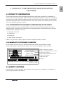
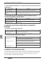
1 "Tips", "Attention", "Warning and "Danger" in this operation manual are defined as follows:
1.2.1 NOTICES REGARDING INSTALLATION
1. The frequency inverter shall not be installed on combustibles that may induce the risk of fire.
2. The frequency inverter shall not be installed at places with direct sunlight.
3. The frequency inverter shall not be installed in areas with hazardous ratings; eg environment with
explosive gases or combustible dusts.
4. Do not install the Frequency inverter if damaged or lf components are missing. Installation may lead to
personal injury, fire or other accidents.
5. Do not remove or modify the frequency inverter without authorization.
6. Do not drop foreign matter into the frequency inverter (eg: wire off cuts of wire, metal fillings, dust etc)
Entry of foreign matter may result in destruction of the frequency inverter.
7. The frequency inverter shall be installed only where the supporting structure is able to bear its weight.
1.2.2 NOTICES REGARDING INSTALLATION
1. All wiring must be completed by a certified electrician. If the wiring must be accordance to local
regulations. All wiring must be done in a manner to ensure the safety of the equipment and all
individuals.
2. Do not open the front cover of the frequency inverter for 10 minutes after removing power from the unit,
Doing so may result in electric shock.
3. The earth terminal of frequency inverter must be reliably grounded. A poor earth connection may result
in electric shock.
4. Connection of AC power onto the output terminals U、V and W of frequency inverter, will damage the
frequency inverter, and may lead to personal injury.
5. Confirm that the input voltage and frequency converter are in consistent with rated voltage value
6. To avoid the risk of damage to the frequency inverter, confirm that the motor and frequency converter
are of equivalent voltage and current ratings.
7. A brake resistor cannot be connected onto the (+), (-) of DC bus directly. Direct connection to the DC
Bus will cause excessive heat and may cause a fire.
¾ Warning: These requirements must be followed to avoid the risk of injuries to
personnel and the loss of material
¾ Danger: Without operation according to these requirements, serious damage to
equipment or injuries to personnel may result.
¾ Tips: Tips for some useful information.
¾ Attention: Matter requires attention during operation.

Product Confirmation And Operation Cautions 3
A510 Series Heavy-Duty Closed-Loop Vector Inverter User Manual
1
1.2.3 CAUTIONS REGARDING SAFE OPERATION
1. Do not operate the frequency inverter with wet hands. To do so may result in electric shock.
2. Please install the front cover prior to power up and do not remove the cover while power is on. Removal
of front cover may result in electric shock.
3. Do not touch the terminals of frequency inverter, while the frequency inverter is powered on, even if the
motor is stopped. To do so will result in electric shock.
4. If the auto-restart function is enabled, do not approach the load as it may restart suddenly after the
alarm has been removed and this may result in a personal injury.
5. To avoid the risk of personal and property damage, ensure the system is safe before restarting.
6. Please set additional emergency stop and isolation switches to avoid the risk of personal injury.
7. Do not touch the cooling fins of the heat sink and direct current (DC) choke as temperature can be very
high. This may result in personal injury.
1.2.4 CAUTIONS REGARDING SAFE MAINTENANCE
1. Maintenance operations and device replacement only can be done by trained professional
maintenance staff. During operation use only insulated tools. It is strictly prohibited to leave debris and
metal in the frequency inverter. Doing so will increase the likely hood of electric shock, fire, and
personal and property damage.
2. After replacement of the control board, corresponding parameters must be set before placing into
operation to avoid the risk of property damage.
1.3 GENERAL OPERATION INFORMATION
1.3.1 GENNERAL INFORMATION REGARDING MOTOR OPERATION
1. The temperature of the driven motor when being run from a frequency inverter can be a little higher
than if run from standard industrial power supply, especially with long-term operation at low speed, the
operation life of a motor can be affected due to the effect of poorer heat dissipation. In these cases, the
load on the motor can be reduced or additional cooling can be applied to the motor .
2. With some equipment there can sometimes be resonance due to the natural vibration frequency of the
mechanical system. To remove this consider applying a flexible coupling and insulation rubber, or using
the frequency skipping parameters within of the frequency to avoid the resonant frequency points within
the operating range.
3. When operating a motor from a frequency inverter, there can more motor noise than when running from
a fixed industrial power supply. In order to reduce the noise, the carrier frequency of frequency inverter
can be changed if required.
1.3.2 GENERAL INFORMATION FOR USE WITH SPECIAL MOTORS
1. For high-speed motors, if the set frequency of frequency inverter is above 120Hz, please conduct
combination test with the motor to ensure it can be operated safely.
2. For synchronous motors, please contact the manufacturer for consultation.
3. Operation of single-phase motors cannot be achieved with this model frequency inverter. Even if using
a single input phase, there will be a three-phase output. Please use with three-phase motors only.

4 Product Confirmation And Operation Cautions
A510 Series Heavy-Duty Closed-Loop Vector Inverter User Manual
1 1.3.3 AMBIENT ENVIRONMENT
For indoor use with temperature range of 10 to +45°C, humidity below 95% (without condensation of
moisture), no dust, no direct sunlight, no corrosive gas, no combustible gas, no oil mist, no steam, no water
or floating fiber or metal particles. If special requirements beyond these are required, please consult your
supplier.
1.3.4 GENERL INFORMATION FOR THE CONNECTION OF PERIPHERAL
EQUIPMENT
1. For the protection of wiring and the Frequency Inverter, please include circuit breakers on the input side.
Please select devices with an appropriate capacity that provides the best protection.
2. If installing electromagnetic contactor on the output side of frequency inverter, please ensure the after
frequency inverter and motor have stopped running before operating the contactor.
3. When using a thermal relay with a frequency inverter and when long cable runs are used, nuisance
tripping may occur due to high-frequency current flowing and the capacitive effect within wiring. In this
case, please lower the carrier frequency, or apply an output filter.
4. To reduce noise interference and to meet emissions standards the Frequency Inverter is fitted with a
RFI filter. Screened cable must be used between the motor and the Frequency Inverter. The screen of
the cable must be effectively earthed at both ends.
5. It is recommended that all control wiring is done using cable with a compact low impedance shield.
Failure to use a shielded control cable may lead to the Frequency Inverter receiving false input signals.
1.3.5 TRANSPORTATION AND STORAGE
1. During product handling, please capture the both sides of the bottom of the entity, rather than the cover
or parts only.
2. Please do not make the parts of plastic excessive forced, otherwise, there can be falling down or
damage.
3. When it is for temporary storage and long-term storage, pay attention to the followings:
1)Try to be packaged in the packing case of our company as the original package for storage.
2)Long-term of storage will lead to the characteristics of electrolytic capacitor worsen, therefore, it
shall be powered on every half year at least, and with conduction time more than half an hour, and
the input voltage must be risen to the rated value gradually with voltage regulator.
1.4 SAFE DISPOSAL
1. Electrolytic capacitor in the frequency converter may explode if incinerated.
2. Harmful and toxic gas will be produced if the frequency inverter is incinerated.
3. Please classify and dispose of the frequency inverter as industrial waste.
1.5 OTHER CAUTIONS
1. This product should not be used in life support devices and other applications directly concerned with
human safety.
2. If serious accidents or serious losses could be caused due to the operation or failure of this product,
please install appropriate safety devices to ensure total safety.

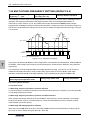
Production Introduction 5
A510 Series Heavy-Duty Closed-Loop Vector Inverter User Manual
2
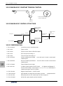
2. PRODUCTION INTRODUCTION
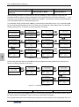
2.1 INVERTER MODEL
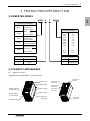
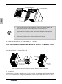
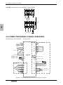
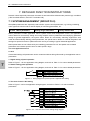
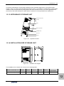
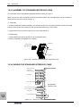
2.2 PRODUCT APPEARANCE
z Appearance Type I
Suitable Mode: A510-4T0011H ~ A510-4T0110H
Terminal baffle
Wiring entrace
of control loop
Wiring entrance
of extension loop
Wiring entrace of
major loop
Lower housing
Upper housing
Operating pannel
Upper cover
Extension unit
terminal 3
Extension unit
terminal 2
Extension unit
terminal 1
Major loop
terminal
Control loop
terminal
A310 – 4 T 0150H
Product SeriesNumber
A310 Heavy-duty
closed-loop
vector inverter
V220 Miniwatt
closed-loop
vector inverter
V260 High-performance
closed-loop
vector inverter
E300/E310 Miniwatt
universalinverter
E380 universalinverter
C320 Noninductive
current vector
type inverter
Voltage Grade
2220V
4380V
Power Supply Phase
TThree-phase
SSingle-phase
Power Grade(KW)
0011
0015
0022
0030
0040
0055
0075
0090
.
.
1100
1320
1.1
1.5
2.2
3.0
4.0
5.5
7.5
9.0
.
.
110
132
V350
V560
E550
Mini
Mini
Universal inverte
r
Sensorless
A510
A510

6 Production Introduction
A510 Series Heavy-Duty Closed-Loop Vector Inverter User Manual
2
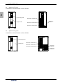
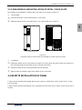
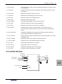
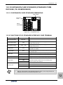
z Appearance Type II
Suitable Mode: A510-4T0150H ~ A510-4T0220H
Operating pannel
Upper cover
Major loop
terminal
Extension unit terminal 1
Extension unit terminal 2
Extension unit terminal 3
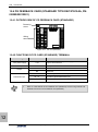
z Appearance Type III
Suitable Mode: A510-4T0300H ~ A510-4T0550H
Upper cover
Operating pannel
4T0370H
Major loop
input terminal
Major loop
output terminal
Extension unit terminal 3
Extension unit terminal 2
Extension unit terminal 1

Production Introduction 7
A510 Series Heavy-Duty Closed-Loop Vector Inverter User Manual
2
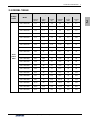
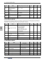
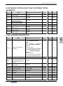
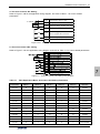
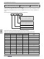
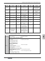
2.3 MODEL TABLE
Voltage
Grade Model
Constant Torque Load Variable Torque Load
Rated
capacity
(KVA)
Adaptive
motor
(KW)
Rated
current
(A)
Rated
capacity
(KVA)
Adaptive
motor
(KW)
Rated
current
(A)
Three
phase
380V
A510-4T0011H 2.0 1.1 3.0 2.4 1.5 3.7
A510-4T0015H 2.4 1.5 3.7 3.6 2.2 5.5
A510-4T0022H 3.6 2.2 5.5 4.9 3.0 7.5
A510-4T0030H 4.9 3.0 7.5 6.3 4.0 9.5
A510-4T0040H 6.3 4.0 9.5 8.6 5.5 13.0
A510-4T0055H 8.6 5.5 13.0 11.2 7.5 17.0
A510-4T0075H 11.2 7.5 17.0 13.8 9.0 21
A510-4T0090H 13.8 9.0 21 16.5 11 25
A510-4T0110H 16.5 11 25 21.7 15 33
A510-4T0150H 21.7 15 33 25.7 18.5 39
A510-4T0185H 25.7 18.5 39 29.6 22 45
A510-4T0220H 29.6 22 45 39.5 30 60
A510-4T0300H 39.5 30 60 49.4 37 75
A510-4T0370H 49.4 37 75 62.5 45 95
A510-4T0450H 62.5 45 95 75.7 55 115
A510-4T0550H 75.7 55 115 98.7 75 150
A510-4T0750H 98.7 75 150 115.8 90 176
A510-4T0900H 115.8 90 176 138.2 110 210
A510-4T1100H 138.2 110 210 171.1 132 260
A510-4T1320H 171.1 132 260 204 160 310

8 Production Introduction
A510 Series Heavy-Duty Closed-Loop Vector Inverter User Manual
2
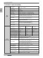
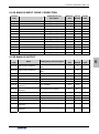
2.4 PRODUCT SPECIFICATIONS
Input
Output
Rated voltage
&frequency 380V~460V 50/60Hz
Output voltage 0~380 V
Output frequency 0.0~300.0Hz
Digital input Standard configuration: 5-circuit digital input (DI)
Digital output Standard configuration: 2-circuit digital output (DO)
Pulse in and out 0~100.0KHz pulse input, can receive OC or 0~24V level signal
(applicable to standard expansion I/O card)
Pulse output 0~100.0KHz pulse output (optional), PWM output mode can be
selected to extend analog output terminal.
Analog input Standard configuration: 0~10V voltage output (AI1);
0~20mA current output (AI2)
Standard I/O board : -10V~10V voltage input
Analog output Two-circuit 0~10V analog output signal
(can be set to 0~20mA current output mode)
Contact output Standard one group of AC 250V/1A normally open and closed
contacts for standard interface card
Control
Characteristics
Control Mode Closed-loop vector
control Open-loop vector
control V/F control
Starting torque 0 speed 220% 0 speed 200% 0 speed 180%
Speed adjustable range 1: 1000 1: 200 1: 100
Steady speed precision ±0.02% ±0.2% ±0.5%
Torque control precision ±5% ±5% --
Torque response time ≦5ms ≦25ms --
Frequency resolution Low-frequency operation mode: 0.01Hz
Frequency resolution Low-frequency operation mode:
digital setting-0.01 Hz, analog setting-highest frequency ×0.1%
Load capacity
Constant Torque mode:
120% - long-term; 160% - 60s; 200% -1s
Variable Torque mode (capacity increase mode):
105% - long-term; 135% - 60s; 165% - 1s
Carrier frequency Low-frequency operation mode:1.5 ~15.0KHz;
Deceleration and
acceleration time 0.01~600.00Sec. / 0.01~6000.0Min.
Magnetic flux brake Achieve rapid brake of the motor by increasing the motor's
magnetic flux (30-120% allowed)
DC brake / band-type DC brake/band-type brake initial frequency: 0.0~ upper limiting
frequency, brake/band-type brake injection current 0.0~100.0%
Strike frequency Low-frequency mode: 0.0~ 50.00Hz;

Production Introduction 9
A510 Series Heavy-Duty Closed-Loop Vector Inverter User Manual
2
Typical
Function
Multi-segment running 16-segment frequency/speed running, independent setting of
the running direction, time and acceleration and deceleration of
each segment
Setting combinations Hundreds of setting combinations of frequency, revolution and
torque
Setting priority Users can choose the priority of frequency./revolution setting
channels, hence allows for different kinds of setting
combinations in application design.
Process PID
Built-in PID controller (process PID, compensation PID), can be
either used independently by external equipment or be used to
create complicated internal compensation control
There are 7-segment optional settings and flexible setting
combination ways for the process PID
Waking & sleeping Process PID has simple sleeping and wakening functions
MODBUS
communication Standard MODBUS communication protocol (optional) allowing
for flexible parameter reading and mapping
Temperature detection Able to detect PT100 or PTC thermo-sensitive elements, hence
allows for over-temperature protection for the motor or external
equipment
Dynamic braking (standard configuration for models below A510-4T0185H)
Actuating voltage: 700~760V, braking ratio: 50~100%
General Functions
Power cut restart; fault self-recovery, motor parameter dynamic/
static self-identification. Start enabling, operation enabling, start
delay, over current suppression, over voltage /under voltage
suppression, V/F custom curve, analog input curve correction,
line brake detection, textile machinery disturbance (frequency
swing) operation
Function
Features
Simulated I/O terminal 8-circuit one-to-one virtual output and input terminals, allowing
for complicated engineering onsite application in an easy way
V/F separate control Users can flexibly and separately set the output frequency and
output voltage value for special engineering application
Spindle scaling control To precisely control the spindle angle, for achieving scaling
positioning
Zero-speed torque
holding
Hold the zero speed and lock the torque, and in the mode of PG
feedback VC control, to enable for constant locking of the
rotating spindle while it is pulled with load
Communication linkage
synchronization
Easily allows for synchronized rotation of multiple rotation, and
free selection of linkage balance of multiple machines based on
current, torque and power, and the exclusive position
synchronized balance function can precisely eliminate
accumulative position error caused by synchronized revolution
error
Load dynamic balance Also allows for dynamic balance of multi-machine load (not
limited to communication linkage) and able to achieve torque
motor characteristics
Strong starting torque For load featuring high inertia and high static friction, super
strong starting torque for certain period can be set
Dual motor parameter With two sets of motor parameters (two for both asynchronous
motor and synchronous motor), allowing for dual motor switch
even in the mode of vector control
Synchronous motor
driving Built-in permanent magnet synchronous motor control algorithm

10 Production Introduction
A510 Series Heavy-Duty Closed-Loop Vector Inverter User Manual
2
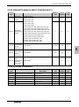
Function
Features
Compensation PID Especially built-in compensation PID, flexibly allowing for tension
control, drawing machine control and other special applications
Timer 3 built-in timers: 5 kinds of time, 5 kinds of trigger modes,
multiple door access signals and working modes, and 7 kinds of
output signals
Counter 2 built-in counters: time margin selection, 4 kinds of trigger
modes and 7 kinds of output signal
Quick Setup
Application macro: allowing for conveniently setting and partially
curing multiple common group parameters and simplifying
parameter setting for common applications
System macro: allowing for conveniently switching equipment’s
working mode, and automatically redefining local parameters
Parameter testing Any un-stored parameter tested on site can be stored with one
key or abandoned and restored to original value
Parameter display Allowing for automatically shielding parameters of unused
functional modules or selectively displaying modified, stored or
changed parameters
Protection
Function
Power supply Under voltage protection, input phase failure protection and
three-phase power supply unbalancing protection
Running protection
Over current protection, over voltage protection, inverter over
temperature protection, inverter overload protection, motor
overload protection, output phase lack protection, and module
drive protection
Equipment abnormity Current detected abnormity, EEPROM memory abnormity, and
abnormal control unit, motor over temperature, MC pull-in fault,
and temperature acquisition loop fault
Motor connection Motor not connected, motor’s three-phased parameters
unbalanced and parameter misidentification
Extension card Detect and protect the extension card for compatibility or conflict
Environment
Installation environment Indoor vertical installation, not subjecting to direct sunshine, free
of dust, corrosive and flammable gas, oil mist, vapor and free of
drips or salt
Altitude 0~1000m. The output current capability drops by 10% for every
rise of 1000 m
Ambient temperature Working ambient temperature: -10 ℃~ +45 ; ℃
storage ambient temperature: -20℃ ~ +60℃
Humidity Below 95%, no condensation
Vibration < 6m/s2

Installation Of Frequency Inverter 11
A510 Series Heavy-Duty Closed-Loop Vector Inverter User Manual
3
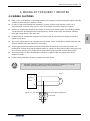
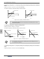
3. INSTALLATION OF FREQUENCY INVERTER
3.1 INSTALLATION OF FREQUENCY INVERTER
This series of frequency inverters are wall-mounted or cabinet frequency inverters, which should be
installed vertically. Please install the frequency inverter within an appropriate enclosure with sufficient
ventilation.
Please refer to 1.3.3 for installation environment. If there is special installation requirement from customer,
please contact with manufacturer in advance.
3.1.1 MOUNTING SURFACE
When the ambient temperature is exceeds the specified rating, or the load is too heavy, the temperature of
frequency inverters heat sink and base may rise to around 90°C, therefore the frequency inverter must be
installed on surfaces which can withstand temperatures in excess of this.
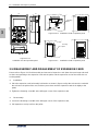
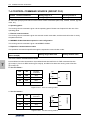
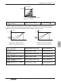
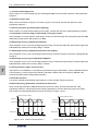
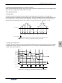
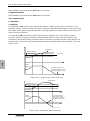
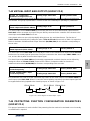
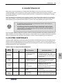
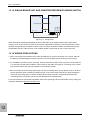
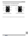
3.1.2 INSTALLATION SPACE
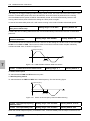
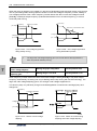
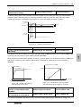
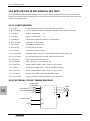
Requirements for installation spacing distance of single frequency inverter are as shown in Figure 3-1-A
and Figure 3-1-B. Reserve enough space around the frequency inverter.
Figure 3-1-B
Installation spacing distance (15KW above)
Figure 3-1-A
Installation spacing distance (11KW below)
DANGER
Please install it on flame-retardant object such as metal,
otherwise may cause fire.
!
50mm above
120mm above
Fan
exhaust
120mm above
50mm above 150mm abov
e
350mm above
350mm above
150mm above
Fan
exhaust

12 Installation Of Frequency Inverter
A510 Series Heavy-Duty Closed-Loop Vector Inverter User Manual
3
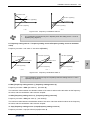
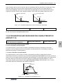
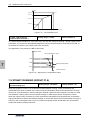
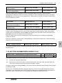
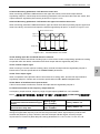
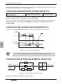
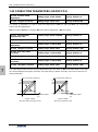
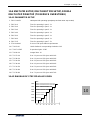
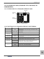
3.1.3 MULTIPLE INSTALLATIONS
For installations with more than 2 frequency inverters mounted in an enclosure together, please conduct
parallel installation as shown in Figure 3-3. If there is no choice but vertical installation, please consider
using a partition plate as shown in Figure 3-2, to make ensure there is no influence on upper frequency
inverter from the lower frequency inverter.
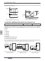
3.2 SIZE AND ASSEMBLY OF OPERATION PANEL
A510 series inverters are configured as standard with the following two kinds of LCD operational panel; The
models below 11KW are configured with shuttle-type panel.
Baffle plate
Frequency
inverter
Frequency
inverter
Figure 3-3 Installation sizes of right and
left frequency inverters (4.0KW above)
Figure 3-2 Installation spacing between
upper and lower frequency inverters
C
A
A
A
A
B
B
Right-and-left space Upper-and-lower space
Align the upper part
D
D
A-50mm above B-30mm above
C-20mm above D-120mm above
¾ Horizontally close installations (Figure 3-2) are allowed for 4.0KW below, and
-10℃~45 environmental temperature.℃
¾ For parallel installation of frequency inverters with different sizes, please install by
aligning the upper parts of all the frequency inverters, allowing room for replacement
of cooling fan.
¾ Please don’t install frequency inverter in the environment where loose particles (eg.
cotton, lint, dust etc) may cause a blockage of the cooling fan. When operating in
such environment, please install in a suitable cabinet that offers suitable protection.
¾ If installing at a location beyond 1000m above sea level, the frequency inverters
output must be de-rated. See 2.4 product technical indexes and specifications for
details.
Page is loading ...
Page is loading ...
Page is loading ...
Page is loading ...
Page is loading ...
Page is loading ...
Page is loading ...
Page is loading ...
Page is loading ...
Page is loading ...
Page is loading ...
Page is loading ...
Page is loading ...
Page is loading ...
Page is loading ...
Page is loading ...
Page is loading ...
Page is loading ...
Page is loading ...
Page is loading ...
Page is loading ...
Page is loading ...
Page is loading ...
Page is loading ...
Page is loading ...
Page is loading ...
Page is loading ...
Page is loading ...
Page is loading ...
Page is loading ...
Page is loading ...
Page is loading ...
Page is loading ...
Page is loading ...
Page is loading ...
Page is loading ...
Page is loading ...
Page is loading ...
Page is loading ...
Page is loading ...
Page is loading ...
Page is loading ...
Page is loading ...
Page is loading ...
Page is loading ...
Page is loading ...
Page is loading ...
Page is loading ...
Page is loading ...
Page is loading ...
Page is loading ...
Page is loading ...
Page is loading ...
Page is loading ...
Page is loading ...
Page is loading ...
Page is loading ...
Page is loading ...
Page is loading ...
Page is loading ...
Page is loading ...
Page is loading ...
Page is loading ...
Page is loading ...
Page is loading ...
Page is loading ...
Page is loading ...
Page is loading ...
Page is loading ...
Page is loading ...
Page is loading ...
Page is loading ...
Page is loading ...
Page is loading ...
Page is loading ...
Page is loading ...
Page is loading ...
Page is loading ...
Page is loading ...
Page is loading ...
Page is loading ...
Page is loading ...
Page is loading ...
Page is loading ...
Page is loading ...
Page is loading ...
Page is loading ...
Page is loading ...
Page is loading ...
Page is loading ...
Page is loading ...
Page is loading ...
Page is loading ...
Page is loading ...
Page is loading ...
Page is loading ...
Page is loading ...
Page is loading ...
Page is loading ...
Page is loading ...
Page is loading ...
Page is loading ...
Page is loading ...
Page is loading ...
Page is loading ...
Page is loading ...
Page is loading ...
Page is loading ...
Page is loading ...
Page is loading ...
Page is loading ...
Page is loading ...
Page is loading ...
Page is loading ...
Page is loading ...
Page is loading ...
Page is loading ...
Page is loading ...
Page is loading ...
Page is loading ...
Page is loading ...
Page is loading ...
Page is loading ...
Page is loading ...
Page is loading ...
Page is loading ...
Page is loading ...
Page is loading ...
Page is loading ...
Page is loading ...
Page is loading ...
Page is loading ...
Page is loading ...
Page is loading ...
Page is loading ...
Page is loading ...
Page is loading ...
Page is loading ...
Page is loading ...
Page is loading ...
Page is loading ...
Page is loading ...
Page is loading ...
Page is loading ...
Page is loading ...
Page is loading ...
Page is loading ...
Page is loading ...
Page is loading ...
Page is loading ...
Page is loading ...
Page is loading ...
Page is loading ...
Page is loading ...
Page is loading ...
Page is loading ...
Page is loading ...
Page is loading ...
Page is loading ...
Page is loading ...
Page is loading ...
Page is loading ...
Page is loading ...
Page is loading ...
Page is loading ...
Page is loading ...
Page is loading ...
Page is loading ...
Page is loading ...
Page is loading ...
Page is loading ...
Page is loading ...
Page is loading ...
Page is loading ...
Page is loading ...
Page is loading ...
Page is loading ...
Page is loading ...
Page is loading ...
Page is loading ...
Page is loading ...
Page is loading ...
Page is loading ...
Page is loading ...
Page is loading ...
Page is loading ...
Page is loading ...
Page is loading ...
Page is loading ...
Page is loading ...
Page is loading ...
Page is loading ...
Page is loading ...
Page is loading ...
Page is loading ...
Page is loading ...
Page is loading ...
Page is loading ...
Page is loading ...
Page is loading ...
Page is loading ...
Page is loading ...
Page is loading ...
Page is loading ...
Page is loading ...
Page is loading ...
Page is loading ...
Page is loading ...
Page is loading ...
Page is loading ...
Page is loading ...
Page is loading ...
Page is loading ...
Page is loading ...
Page is loading ...
Page is loading ...
Page is loading ...
-
 1
1
-
 2
2
-
 3
3
-
 4
4
-
 5
5
-
 6
6
-
 7
7
-
 8
8
-
 9
9
-
 10
10
-
 11
11
-
 12
12
-
 13
13
-
 14
14
-
 15
15
-
 16
16
-
 17
17
-
 18
18
-
 19
19
-
 20
20
-
 21
21
-
 22
22
-
 23
23
-
 24
24
-
 25
25
-
 26
26
-
 27
27
-
 28
28
-
 29
29
-
 30
30
-
 31
31
-
 32
32
-
 33
33
-
 34
34
-
 35
35
-
 36
36
-
 37
37
-
 38
38
-
 39
39
-
 40
40
-
 41
41
-
 42
42
-
 43
43
-
 44
44
-
 45
45
-
 46
46
-
 47
47
-
 48
48
-
 49
49
-
 50
50
-
 51
51
-
 52
52
-
 53
53
-
 54
54
-
 55
55
-
 56
56
-
 57
57
-
 58
58
-
 59
59
-
 60
60
-
 61
61
-
 62
62
-
 63
63
-
 64
64
-
 65
65
-
 66
66
-
 67
67
-
 68
68
-
 69
69
-
 70
70
-
 71
71
-
 72
72
-
 73
73
-
 74
74
-
 75
75
-
 76
76
-
 77
77
-
 78
78
-
 79
79
-
 80
80
-
 81
81
-
 82
82
-
 83
83
-
 84
84
-
 85
85
-
 86
86
-
 87
87
-
 88
88
-
 89
89
-
 90
90
-
 91
91
-
 92
92
-
 93
93
-
 94
94
-
 95
95
-
 96
96
-
 97
97
-
 98
98
-
 99
99
-
 100
100
-
 101
101
-
 102
102
-
 103
103
-
 104
104
-
 105
105
-
 106
106
-
 107
107
-
 108
108
-
 109
109
-
 110
110
-
 111
111
-
 112
112
-
 113
113
-
 114
114
-
 115
115
-
 116
116
-
 117
117
-
 118
118
-
 119
119
-
 120
120
-
 121
121
-
 122
122
-
 123
123
-
 124
124
-
 125
125
-
 126
126
-
 127
127
-
 128
128
-
 129
129
-
 130
130
-
 131
131
-
 132
132
-
 133
133
-
 134
134
-
 135
135
-
 136
136
-
 137
137
-
 138
138
-
 139
139
-
 140
140
-
 141
141
-
 142
142
-
 143
143
-
 144
144
-
 145
145
-
 146
146
-
 147
147
-
 148
148
-
 149
149
-
 150
150
-
 151
151
-
 152
152
-
 153
153
-
 154
154
-
 155
155
-
 156
156
-
 157
157
-
 158
158
-
 159
159
-
 160
160
-
 161
161
-
 162
162
-
 163
163
-
 164
164
-
 165
165
-
 166
166
-
 167
167
-
 168
168
-
 169
169
-
 170
170
-
 171
171
-
 172
172
-
 173
173
-
 174
174
-
 175
175
-
 176
176
-
 177
177
-
 178
178
-
 179
179
-
 180
180
-
 181
181
-
 182
182
-
 183
183
-
 184
184
-
 185
185
-
 186
186
-
 187
187
-
 188
188
-
 189
189
-
 190
190
-
 191
191
-
 192
192
-
 193
193
-
 194
194
-
 195
195
-
 196
196
-
 197
197
-
 198
198
-
 199
199
-
 200
200
-
 201
201
-
 202
202
-
 203
203
-
 204
204
-
 205
205
-
 206
206
-
 207
207
-
 208
208
-
 209
209
-
 210
210
-
 211
211
-
 212
212
-
 213
213
-
 214
214
-
 215
215
-
 216
216
-
 217
217
-
 218
218
-
 219
219
-
 220
220
-
 221
221
-
 222
222
-
 223
223
-
 224
224
-
 225
225
-
 226
226
-
 227
227
-
 228
228
-
 229
229
-
 230
230
-
 231
231
-
 232
232
-
 233
233
-
 234
234
-
 235
235
-
 236
236
-
 237
237


Ask a question and I''ll find the answer in the document
Finding information in a document is now easier with AI
Related papers


Other documents
-
TECO A510-2010-H3 User manual
-
 Inovance MD500 User guide
-
Mitsubishi Electric FR-A8APR User manual
-
 HNC Electric HV580L-7R5G3 User manual
-
-
ABB PVS800-57B User manual
-
 Veichi AC100-T3-018G User manual
-
 AE-TECHNOLOGY AE-V81 User manual
-
 Sunfar E500-2S0040(B) User manual
-
 AE-TECHNOLOGY AE-V812 User manual


