Jacobsen 544914 Owner's manual
- Category
- Mini tillers
- Type
- Owner's manual

GB
Safety & Operation
Manual
GA 60 PT Aerator
Model 544914
4117238-Rev A

Litho in U.S.A. 12–2002
2002 TEXTRON INC.
All Rights Reserved.
GENERAL INFORMATION
IMPORTANT!
THIS MANUAL WILL AID YOU IN THE SAFE
OPERATION AND PROPER MAINTENANCE OF
YOUR EQUIPMENT. READ MANUAL THOROUGHLY
BEFORE ATTEMPTING OPERATION. IF ANY
PORTION IS NOT CLEARLY UNDERSTOOD,
CONTACT AN AUTHORIZED DEALER FOR
CLARIFICATION.
To make sure you are fully aware of safety and service
information, the following two symbols are used
throughout this manual.
!!
This symbol is used throughout the manual to
alert you to information about unsafe actions or
situations, and will be followed by the word DANGER,
WARNING, or CAUTION. DANGER indicates
immediate hazards that may result in severe injury or
death. WARNING indicates unsafe actions or situations
that may cause severe injury, death and/or major
equipment or property damage. CAUTION indicates
unsafe actions or situations that may cause injury, and/or
minor equipment or property damage.
NOTE: This appears next to information or instructions
which will help you operate and maintain your
equipment the right way.
WARNING
!
S The information and instructions included
in this manual alert you to certain things
you should do very carefully. If you do not,
you could:
• hurt yourself or others
• hurt the next person who operates the
equipment
• damage the equipment.
S This manual contains essential operation
and safety information and must remain
with the unit at all times, within easy ac-
cess of any operator.
Additional manuals are available through your dealer.
IMPORTANT!
THIS EQUIPMENT SHOULD NOT BE MODIFIED OR
ADDED TO WITHOUT THE MANUFACTURER’S
AUTHORIZATION.
WARNING
!
S Altering this equipment in any manner
which adversely affects the equipments
operation, performance, durability or use,
may cause hazardous conditions.
Direct any inquiries to:
Textron Golf,Turf and Specialty Products
Attn: Director of Engineering
P.O. Box 7708
Charlotte, NC 28241–7708 USA
SPECIFICATION INFORMATION
All information contained in this manual is the latest
available at the time of printing. Textron Golf,Turf and
Specialty Products reserves the right to make changes
at any time without notice.
Whenever a name brand product is specified, an
equivalent product may be used unless stated otherwise.
CHANGE OF OWNERSHIP OR ADDRESS
Textron Golf,Turf and Specialty Products makes every
effort to keep owners informed of all safety related
information. Therefore, changes in ownership and/or
address should be reported to the manufacturer.
Your dealer has REGISTRATION CHANGE FORMS
which will be filled out and filed by the dealer for his
records, and a copy will be sent to the manufacturer.
DEALER INFORMATION
For your nearest dealer location write to:
Textron Golf,Turf and Specialty Products
Attn: Sales
P.O. Box 7708
CHarlotte, NC 28241–7708 USA
In the USA and Canada call 1–800–228–4444 (dealer
information only).

1
TABLE OF CONTENTS
1 Operation Safety 2. . . . . . . . . . . . . . . . . . . . . . . . . . . . . . . . . . . . . . . . . . . . . . . . .
2 Identification 3
. . . . . . . . . . . . . . . . . . . . . . . . . . . . . . . . . . . . . . . . . . . . . . . . . . . . .
2.1 Model Number and Serial Number 3. . . . . . . . . . . . . . . . . . . . . . . . . . . . . . . . .
3 Service Parts and Support Material 3. . . . . . . . . . . . . . . . . . . . . . . . . . . . . . . .
4 Specifications 3
. . . . . . . . . . . . . . . . . . . . . . . . . . . . . . . . . . . . . . . . . . . . . . . . . . . .
4.2 Turf Utility Tractor Specifications 3. . . . . . . . . . . . . . . . . . . . . . . . . . . . . . . . . . .
5 Set Up 4. . . . . . . . . . . . . . . . . . . . . . . . . . . . . . . . . . . . . . . . . . . . . . . . . . . . . . . . . . .
5.1 Set Up Utility Tractor 4. . . . . . . . . . . . . . . . . . . . . . . . . . . . . . . . . . . . . . . . . . . . .
5.2 Removing From Pallet 4. . . . . . . . . . . . . . . . . . . . . . . . . . . . . . . . . . . . . . . . . . . .
5.3 Installing Tines 5. . . . . . . . . . . . . . . . . . . . . . . . . . . . . . . . . . . . . . . . . . . . . . . . . .
6 Operation 6. . . . . . . . . . . . . . . . . . . . . . . . . . . . . . . . . . . . . . . . . . . . . . . . . . . . . . . .
6.1 Pre–Operation Check 6. . . . . . . . . . . . . . . . . . . . . . . . . . . . . . . . . . . . . . . . . . . .
6.2 Beginning Aeration 6. . . . . . . . . . . . . . . . . . . . . . . . . . . . . . . . . . . . . . . . . . . . . . .
7 MAINTENANCE 7. . . . . . . . . . . . . . . . . . . . . . . . . . . . . . . . . . . . . . . . . . . . . . . . . . .
7.1 Daily Maintenance 7. . . . . . . . . . . . . . . . . . . . . . . . . . . . . . . . . . . . . . . . . . . . . . .
7.2 Tires 7. . . . . . . . . . . . . . . . . . . . . . . . . . . . . . . . . . . . . . . . . . . . . . . . . . . . . . . . . . .
7.3 Gear Box 8. . . . . . . . . . . . . . . . . . . . . . . . . . . . . . . . . . . . . . . . . . . . . . . . . . . . . . .
7.4 Towing 8. . . . . . . . . . . . . . . . . . . . . . . . . . . . . . . . . . . . . . . . . . . . . . . . . . . . . . . . .
8 Storage 8. . . . . . . . . . . . . . . . . . . . . . . . . . . . . . . . . . . . . . . . . . . . . . . . . . . . . . . . . .
9 Torque Chart 9
. . . . . . . . . . . . . . . . . . . . . . . . . . . . . . . . . . . . . . . . . . . . . . . . . . . . .
10 Tine Holders 10. . . . . . . . . . . . . . . . . . . . . . . . . . . . . . . . . . . . . . . . . . . . . . . . . . . .
11 Tines 11
. . . . . . . . . . . . . . . . . . . . . . . . . . . . . . . . . . . . . . . . . . . . . . . . . . . . . . . . . . .
12 Warranty 14–15. . . . . . . . . . . . . . . . . . . . . . . . . . . . . . . . . . . . . . . . . . . . . . . . . . . .
13 Index 16
. . . . . . . . . . . . . . . . . . . . . . . . . . . . . . . . . . . . . . . . . . . . . . . . . . . . . . . . . . .

1 OPERATION SAFETY
2
WARNING
!
EQUIPMENT OPERATED IMPROPERLY OR BY
UNTRAINED PERSONNEL CAN BE DANGEROUS
This is heavy equipment. Improper use, or operat-
ing the unit in areas that may cause it to overturn,
could cause serious injury or death to you the oper-
ator or bystanders.
READ and understand the operator’s manual be-
fore attempting to operate this unit.
Immediately replace any warning and/or safety
decal that becomes damaged or difficult to read.
This product is heavy equipment and may present a
crush hazard unless safety precautions are taken.
Allow ONLY trained and authorized persons to op-
erate this unit. NEVER allow children to operate this
unit. Local regulations may restrict the age of the
operator.
Use ONLY the standard drawbar approved by the
tractor manufacturer. The height from the ground
to the top of the drawbar must be 13 to 19.7 inches
(330–500 mm).
Never operate the unit while under the influence of
alcohol or drugs.
Never operate the unit while people, especially chil-
dren, or pets are nearby.
Keep in mind that the operator or user is responsi-
ble for accidents or hazards occurring to other
people or property.
BEFORE using the unit, always inspect it for prob-
lems. If something is wrong, DO NOT USE IT. Fix the
problem before using the unit to prevent possible
injury.
WHILE using the unit, if something is found to be
wrong, STOP using it. Fix the problem before the
unit is used again.
Operate the machine up and down the slope (verti-
cally), not across the face of the slope (horizon-
tally).
ALWAYS use good judgement when operating on
or near hills or slopes. NEVER start or stop sud-
denly, you may cause unstable operating condi-
tions. NEVER change directions abruptly or make
sharp turns on slopes.
DO NOT place hands or feet near or under moving
parts at any time.
Check work area and remove foreign objects which
may be a hazard to the operator, bystanders or
damage the equipment.
To prevent damage to the unit or other equipment,
BE SURE all under ground obstacles are clearly
marked.
Make sure all shields and guards are in place to
prevent possible injury.
BE SURE the PTO on the tractor is disengaged
when attaching the drive shaft.
Stay clear of the drive shaft when the PTO is
engaged. The drive shaft can catch clothing and
result in serious injury or death.
DO NOT make any adjustments or perform any
maintenance while the PTO is engaged.

IDENTIFICATION 2
3
2 IDENTIFICATION
THESE IDENTIFICATION NUMBERS MUST APPEAR
ON ALL CORRESPONDENCE CONCERNING THIS
UNIT.
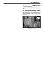
2.1 MODEL NUMBER & SERIAL NUMBER
Both the Model Number and Serial Number are on the
identification nameplate located behind the gear box
(See Fig. 1).
1
FRONT
OF UNIT
Figure 1
1. Identification Nameplate

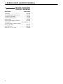
3 SERVICE PARTS & SUPPORT MATERIAL
4
3 SERVICE PARTS AND
SUPPORT MATERIAL
Description Part Number. . . . . . . . . . . . . . . . . . . . . . . .
Drive Belt 2701420. . . . . . . . . . . . . . . . . . . . . . . . . . . . . .
Chain, #50 sealed roller, 69 links 891956. . . . . . . . . . .
Connector, #50 sealed 522123. . . . . . . . . . . . . . . . . . . .
Chain Lubricant, Spray 523248. . . . . . . . . . . . . . . . . . . .
Wool Grease 893078. . . . . . . . . . . . . . . . . . . . . . . . . . . .
Parts and Maintenance Manual 4117235. . . . . . . . . . . .
Coring tines See pages 14 – 15. . . . . . . . . . . . . . . . . . .
Touch up paint, Jacobsen Orange
16 oz. (.5L) spray 2700345. . . . . . . . . . . . . . . . . . . . . . .
1 qt. (.95L) can 2700351. . . . . . . . . . . . . . . . . . . . . . . . . .
Black, 16 oz. (.5L) spray 814294. . . . . . . . . . . . . . . . . .

SPECIFICATIONS 4
5
4 SPECIFICATIONS
(subject to change without notice)
Aerator:
Core Diameter 1/4” (6.5 mm). . . . . . . . . . . . . . . . . . .
3/8” (9.5 mm)
1/2” (13 mm)
5/8” (16 mm)
Standard 3/4” (19 mm). . . . . . . . . . . . . . . . . . . . . . .
Core Spacing (width) 2 1/2” (63 mm). . . . . . . . . . . .
Core Spacing (length) 3 1/2” to 5” variable. . . . . . .
(89 mm to 127 mm)
**Core Depth 2 1/2” (64 mm) to 4” (102 mm). . . . .
Coring Width 60” (1524 mm). . . . . . . . . . . . . . . . . . .
**Maximum attainable depth may vary depending on
soil conditions.
Dimensions:
Width 90” (2286 mm). . . . . . . . . . . . . . . . . . . . . . . . .
Length 78” (1981 mm). . . . . . . . . . . . . . . . . . . . . . . .
Height 43” (1092 mm). . . . . . . . . . . . . . . . . . . . . . . . .
Weight Total: 1958 lbs. (890 kg). . . . . . . . . . . . . . . .
Axle: 1562 lbs. (710 kg)
Tongue: 396 lbs. (180 kg)
Gear Box
Gear Ratio 1.5 : 1 (increasing). . . . . . . . . . . . . . . . .
Input Speed 540 RPM. . . . . . . . . . . . . . . . . . . . . . . .
Output Speed 810 RPM. . . . . . . . . . . . . . . . . . . . . .
Oil SAE EP 80–90 Gear Lube. . . . . . . . . . . . . . . . . .
2.25 qt. (2.1 L)
Tires: 23 x 10.5 – 12 Turf Tires. . . . . . . . . . . . . . . . . . . .
18 psi (125 kPa)
Standards
Conforms to European Community (EC) standard
89/392 and amendments 91/368 and 93/44/EEC.
4.2 TURF UTILITY TRACTOR
SPECIFICATIONS
Minimum weight of turf utility tractor – 2700 lbs. (1225
kg).
Required PTO horsepower of 25–45 hp.
NOTE: Actual horsepower required depends on soil
conditions.
Maintain a PTO speed of 540 RPM.
Standard drawbar approved by tractor manufacturer.
Drawbar height must be 13 – 19.7 inches (330–500 mm)
from ground to top of drawbar.
Hydraulic system with 1800 to 2250 psi (12.4 to 15.5
MPa) maximum pressure. Minimum output of 3 gallon
per minute (11.4 L/min). Quick couplers located at rear of
tractor.
Braking system capable of controlling the tractor and the
towed GA 60PT weighing 1958 lbs. (890 Kg).
Governor and properly geared transmission capable of
controlling ground speed from 1 to 2 mph (1.6 to 3.2
km/hr) while aerating.

5 SET UP
6
5 SET UP
5.1 SET UP UTILITY TRACTOR
1. Install and secure a 2” (51mm) tow hitch ball to the
standard tractor drawbar. BE SURE the ball hitch is
a class 2 (3500 lb. capacity) or better ball.
CAUTION
!
Use ONLY the standard drawbar approved by
the tractor manufacturer. The height from the
ground to the top of the drawbar must be 13 to
19.7 inches (330–500 mm).
NOTE: If raising the hydraulic lever lowers the aerator,
the hydraulic lines are reversed. Reverse the
hydraulic lines at the quick couplers.
2. The GA 60PT can produce a maximum hole spacing
of 5” (125 mm). Hole spacings greater than 5” (125
mm) will SEVERELY DAMAGE the aerator
mechanism.
NOTE: The tractor speed MUST BE kept below 2 mph
(3.2 km/hr) and maintain a constant PTO speed of
540 RPM when aerating. BE SURE to use an
engine speed and transmission gear that will result
in a hole spacing of less than 5” (127 mm). Aerating
speeds exceeding the allowable 2 mph (3.2 km/hr)
will SEVERELY DAMAGE the aerator mechanism
components.
Hole
Spacing
Miles
Per
Hour
2.5”
3.7”
5.0”2.0
1.5
1.068 seconds
51 seconds
34 seconds
Approximate
time needed to
drive 100’
Tractor Hole Spacing Chart
Inches
(30.5 Meters) (Km/hr.) (mm)
5.2 REMOVING FROM PALLET
1. Carefully cut and remove all banding securing
aerator, tongue, and drive line to shipping pallet.
2. Locate and secure the six (6) 1/2–13 x 1 1/2” screws
(Part No. 311401), lockwashers (Part No. 120166),
and nuts (Part No. 800544) located in a cloth bag in
the tool box.
3. Using hardware, install and secure the aerator hitch
assembly to the main frame.
4. Using the jack attached to the GA 60PT, raise the GA
60PT high enough to make sure the tongue clears
the ball hitch on the tractors drawbar.
NOTE: Blocks may be needed to properly support the
jack when raising the GA 60PT.
5. Back the tractor up to the GA 60PT. Position the
tractor so the GA 60PT tongue may be lowered onto
the ball hitch.
6. Slowly lower the tongue onto the ball hitch. Tighten
ball grip to ball hitch by turning the square nut on
hitch coupler clockwise until tight.
7. Lock the hydraulic lift control on the tractor in the float
position to relieve hydraulic pressure. This will allow
the hydraulic hoses to be connected more easily.
NOTE: After connecting the hydraulic hoses, BE SURE
to release the hydraulic lift control from the float
position.
8. Raise the aerator heads as high as possible to allow
GA 60PT to be removed from pallet.
NOTE: Place various thickness boards or blocks in front
of the pallet to create a ramp inorder to help prevent
the GA 60PT from dropping to the ground from
pallet during removal.
BE SURE aerator heads are raised to their
maximum height to assure the turf guards do not
catch on pallet.
WARNING
DO NOT allow anyone to stand directly behind
pallet during removal of the GA 60PT.
The weight of the unit may cause the pallet to
slide back quickly when the GA 60PT is
removed.
!
9. Slowly drive the tractor forward to remove GA 60PT
from pallet.
10. Install and secure the drive line to the GA 60PT.

SET UP 5
7
5.3 INSTALLING TINES
WARNING
DO NOT attempt to install tines with the tractor
engine running. Remove key from tractor to
insure the engine will not be started during
tine installation.
Set parking brake on tractor.
Before installing tines or performing any work
under the GA 60PT, always lock the uplatch bar
in place to prevent the accidental lowering of
the aeration heads or the lowering of the heads
due to a loss in hydraulic pressure.
To lock uplatch bar, remove the pin under the
rear of the bar and move it to the upper hole,
making sure the pin passes through the
uplatch bar to lock it in place. Refer to figures
2 and 3.
!
Figure 2
1
3
2
Figure 3
1. Uplatch Bar (Locked position)
2. Pin
3. Lower Hole
1. Insert three (3) tines per holder and torque screws
(see torque chart on page 8). BE SURE tines are
tight against shoulder on tine holder. Open side of
each tine should be positioned towards the rear of
the machine for proper ejection of cores (See Fig. 4).
Figure 4

6 OPERATION
8
6 OPERATION
6.1 PRE–OPERATION CHECK
1. Check grounds area and remove foreign objects
which may be a hazard to the operator or could
damage the equipment.
2. BE SURE all under ground obstacles are clearly
marked.
3. Visually check all moving parts and fasteners, if
broken or loose, replace or tighten. Check for broken
or bent tines, replace as necessary.
4. BE SURE that all shields and guards are in place.
NEVER make adjustments or perform any
maintenance while the PTO is engaged.
6.2 BEGINNING AERATION
CAUTION
!
Position the tractor’s three point hitch arms to clear
the GA 60PT’s hitch and drive line when turning.
The tractor’s three point hitch arms may need to be
removed.
To prevent possible breakage of hydraulic lift cylin-
der brackets on frame, unit MUST BE resting on
down stops while aerating.
NEVER use the hydraulic lift cylinder to adjust
depth of aeration.
AERATING DEPTH ADJUSTMENT
The GA 60PT is designed to aerate at a MAXIMUM
depth of 4” (102 mm). The operator should be aware that,
in extremely hard soil, the machine may not be capable
of pushing the tines 4” (102 mm) into the ground. DO
NOT operate with the depth setting at the 4” (102 mm)
maximum when the tines are only penetrating 2–3 inches
(51–76 mm). Operating under these conditions will
cause premature wear and/or broken components in the
aerator linkage. If the aerator tires consistently ride up off
the turf or bounce up off the turf, the ground is too hard.
NEVER try to aerate at a depth greater than the soil
conditions will allow. The operator must first make a test
run, measure the depth of the holes, and set the depth
adjustment to correspond to soil conditions. After
aerating the area once or twice at that depth to loosen the
sub–soil, it may be possible to lower the settings each
time until the 4” (102 mm) maximum depth can be
accomplished without abusing the GA 60PT.
AGAIN––Aerate a small test plot, measure the depth of
the hole and adjust the depth setting on the GA 60PT to
match it.
If aerating extremely hard soil, additional penetration is
possible with added water, either by rain or irrigation.
Moist ground is easier to aerate than dry ground and is
also easier on the aerator mechanism.
If aerating in soil with rocks or stones, additional
penetration over time may not be possible. The operator
must determine what depth is possible for that area and
be sure not to exceed that depth.
Adjusting the depth from 2 1/2” (64 mm) to 4” (102 mm) is
accomplished by adjusting the 1/2” (13 mm) axle stop
spacers shown in Figure 5.
CAUTION
!
Use extreme caution when backing the GA 60PT.
DO NOT back the GA 60PT with the aerator heads
in the down position. The tines and tine rams will
be SEVERELY DAMAGED.
DO NOT operate the GA 60PT over any hard sur-
faces (ie. driveways, sidewalks, ect.) with aerator
heads in the down position.
With the aerator heads raised, the GA 60PT can be
transported at any reasonable safe speed (10 m.p.h.
maximum). ALWAYS use extreme care when towing
aerator at any speeds above 5 m.p.h.
NOTE: The GA 60PT may be damaged if towed on a
flatbed trailer without the aerator heads lowered.
Place boards or similar type material on trailer to
prevent damage to trailer and/or tines when the
heads are lowered. Place blocks on the downstops
and lower the aerator heads.
1
2
Figure 5
1. Downstop Block
2. Spacers

MAINTENANCE 7
9
7 MAINTENANCE
WARNING
When performing service or maintenance
work on the GA 60PT, ALWAYS lock the
uplatch bar in place to prevent the aeration
heads from being lowered accidentally or due
to a loss in hydraulic pressure. Set the park
brake on the tractor.
If any type of work is to be performed on the
GA 60PT, remove the key from the tractor.
This will prevent the tractor from being acci-
dentally started.
When replacement parts are required, use
genuine RYAN parts or parts with equivalent
characteristics such as type, strength and
material. Failure to do so may result in prod-
uct malfunction and possible injury to the
operator and/or bystanders.
NEVER attempt to perform service or mainte-
nance functions on the GA 60PT if you are
UNTRAINED or UNAUTHORIZED. Improper
maintenance can and will cause hazardous
conditions. For necessary maintenance and
service, contact your authorized RYAN dealer.
When it is necessary to raise the GA 60PT for
any repair or service, use jackstands to help
provide adequate support. DO NOT rely on
hydraulic or mechanical jacks for support.
Immediately replace any warning and/or
safety decal that becomes damaged or diffi-
cult to read.
!
7.1 DAILY MAINTENANCE
1. Check the tire pressure (18 psi, 124 kPa).
2. BE SURE the weight is off of the tires. Lubricate axle
pivots with a standard lithium based lubricant. Refer
to lubrication chart below.
3. Lubricate aerator drive chains with chain lubricant
spray (Part No. 523248).
4. Lubricate the pillow block bearing with a standard
lithium based lubricant. Refer to lubrication chart
below.
5. Lubricate U–joints in the drive line with a standard
lithium based lubricant. Refer to lubrication chart
below.
7.2 TIRES
Keep tires properly inflated to prolong tire life. Check
inflation pressure while the tires are cool. Inspect tread
wear.
Use an accurate, low pressure tire gauge.
Keep tires inflated to the air pressure specified below.
23 x 10.5 – 12 Turf Tires 18 psi (124 kPa). . . . . . . . . .
CAUTION
!
Unless you have the proper training, tools and
experience, DO NOT attempt to mount a tire on
a rim. Improper mounting can produce an ex-
plosion which may result in serious injury.
⊗
⊗
⊗
1
4
6
1. Pillow Block
2. U–Joint (both ends)
3. Center of Drive Line
4. Axle Yoke
5. Axle Yoke
6. Axle Yoke
⊗
5
⊗
2
3
LUBRICATION CHART

7 MAINTENANCE
10
7.3 GEAR BOX
The oil level should be filled up to the rear plug on the
gear box (See Fig. 6).
If oil is needed, use SAE EP 80–90 gear lube. Remove
the vent cap on the gear box and fill until the oil begins to
come out the rear plug hole. Reinstall the rear plug and
vent cap.
FRONT
OF UNIT
1
2
Figure 6
1. Vent Cap
2. Rear Plug
7.4 TOWING
With the aerator heads raised, the GA 60PT can be
transported at any reasonable safe speed (10 m.p.h.
maximum). ALWAYS use extreme care when towing
aerator at any speeds above 5 m.p.h.
NOTE: The GA 60PT may be damaged if towed on a
flatbed trailer without the aerator heads lowered.
Place boards or similar type material on trailer to
prevent damage to trailer and/or tines when the
heads are lowered. Place blocks on the downstops
and lower the aerator heads.

STORAGE 8
11
8 STORAGE
GENERAL
1. Wash the machine thoroughly and lubricate. Repair
and paint damaged or exposed metal.
2. Inspect the machine, tighten all hardware, replace
worn or damaged components.
3. Check to make sure all guards are in place. Replace
any missing or damaged guards.
4. Check to make sure all safety decals are in place and
legible. Replace any missing or damaged decals.
5. Clean the tires thoroughly and store the machine so
the load is off the tires. If machine is not on jack
stands, check tires at regular intervals and inflate as
necessary.
6. Lightly lubricate chains and tines using an aerosol
chain lube to prevent rust.
7. Keep the machine clean, dry and protected from the
elements during storage.
AFTER STORAGE
1. Check oil level in the gear box.
2. Wash the machine thoroughly and lubricate.
3. Inspect the machine, tighten all hardware, replace
worn or damaged components.
4. Check to make sure all guards are in place. Replace
any missing or damaged guards.
5. Check to make sure all safety decals are in place and
legible. Replace any missing or damaged decals.
6. Make certain that the tires are properly inflated.

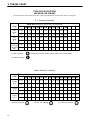
9 TORQUE CHART
12
M4 M5 M6 M7 M8 M10 M12 M14 M16 M18 M20 M22 M24 M27
ft. lbs. 1.5 3 5.2 8.2 13.5 24 43.5 70.5 108 142 195 276 353 530
N·m 2 4 7 11 18 32 58 94 144 190 260 368 470 707
ft. lbs. 2.2 4.5 7.5 12 18.8 35.2 62.2 100 147 202 275 390 498 747
N·m. 3 6 10 16 25 47 83 133 196 269 366 520 664 996
ft. lbs. 2.7 5.2 8.2 15 21.8 43.5 75 119 176 242 330 471 596 904
N·m 3.6 7 11 20 29 58 100 159 235 323 440 628 794 1205
1/4 5/16 3/8 7/16 1/2 9/16 5/8 3/4 7/8 1 1 1/8
ft. lbs. 9 18 31 50 75 110 150 250 378 583 782
N·m 12 24 42 68 102 150 203 339 513 790 1060
ft. lbs. 13 28 46 75 115 165 225 370 591 893 1410
N·m 18 38 62 108 156 224 305 502 801 1211 1912
ft. lbs. 24 40
N·m3354
TORQUE SPECIFICATIONS
HEX HEAD CAP SCREWS
* Grade 5 marking – Minimum commercial quality (Lower quality not recommended).
U.S. Standard Hardware
Grade
Shank Size (Diameter in inches, fine or coarse thread)
SAE
grade
5 *
SAE
grade
8 **
Flangelock
Screw w/
Flangelock
Nut
The torque values shown should be used as a general guideline when specific torque values are not given.
** Grade 8 marking –
Grade
Shank Size (Diameter in millimeters, fine or coarse thread)
Grade
8.8*
Grade
10.9**
Grade
12.9 ***
Metric Standard Hardware
* Grade 8.8 marking – ** Grade 10.9 marking – *** Grade 12.9 marking –
8.8 10.9 12.9

TINE HOLDERS 10
13
4116625.7
4116255.7
4117122.7
4116982.7
Tines Used W/Holder
517486 1/4” Coring Tine
517487 3/8” Coring Tine
Tine Holder 4117122.7 517488 1/2” Coring Tine
547132 1/2” Carbide Tine
523995 1/2” H.D. Tine
Tines Used W/Holder
517487 3/8” Coring Tine
517489 5/8” Coring Tine
Tine Holder 4116255.7 523028 5/8” Coring Tine
523421 3/8” Coring Tine
523472 1/2” Coring Tine
523394 5/8” Coring Tine
838323 1/2” Solid Tine
Tines Used W/Holder
Tine Holder 4116625.7 (Standard) (Standard) 834973 3/4” Coring Tine
523273 3/4” Coring Tine
Tines Used W/Holder
*Tine Holder 4116982.7 523863 1/4” Solid Tine
523864 1/4” Coring Tine
TINE
HOLDERS
*Turf guards (Part No. 4116983.7) must be used when using this tine holder.
(Use 7/8” o.d. tines)
(Use 3/4” o.d. tines)
(Use 1/2” o.d. tines)
(Use 5/8” o.d. tines)
306416
306325
523474
306435
306325
523474
548938
800446
523474
523474
306325
306435

11 TINES
14
838323523394834973523421523864523863 523995
(1/2” o.d.) (5/8” o.d.) (1/2” o.d.) (3/4” o.d.) (7/8” o.d.) (3/4” o.d.) (3/4” o.d.)
TINE P.N. DESCRIPTION HOLE SIZE HOLDER P.N.
523863 1/4” Solid Tine 1/4” x 2 1/2” 4116982.7
523864 1/4” Coring Tine 1/4” x 2 1/2” 4116982.7
517486 1/4” Coring Tine 1/4” x 2 1/2” 4117122.7
517487 3/8” Coring Tine 3/8” x 2 1/2” 4117122.7
523421 3/8” Coring Tine 3/8” x 3 1/4” 4116255.7
517488 1/2” Coring Tine 1/2” x 2 1/2” 4117122.7
523472 1/2” Coring Tine 1/2” x 3 3/4” 4116255.7
523995 1/2” Coring Tine (H.D.) 1/2” x 2 1/2” 4117122.7
547132 1/2” Coring Tine (Carbide tip) 1/2” x 2 1/2” 4117122.7
838323 1/2” Solid Tine 1/2” x 3 3/4” 4116255.7
523394 5/8” Coring Tine 5/8” x 3 3/4” 4116255.7
517489 5/8” Coring Tine 5/8” x 2 1/2” 4116255.7
523028 5/8” Coring Tine 5/8” x 3 3/4” 4116255.7
523273 3/4” Coring Tine 3/4” x 3 3/4” 4116625.7
834973 3/4” Coring Tine (open side) 3/4” x 3 3/4” 4116625.7

TINES 11
15
PART
NUMBER
ACTUAL
LENGTH
HOLE
SIZE
TINE HOLDER
USED
APPLICATION
517486
4 1/4”
(108 mm)
Less penetration (use on hard soils).
1/4” x 2 1/2”
(6 mm x 64 mm)
517487
4 1/4”
(108 mm)
3/8” x 2 1/2”
(10 mm x 64 mm)
Less penetration (use on hard soils).
517488
4 1/4”
(108 mm)
1/2” x 2 1/2”
(13 mm x 64 mm)
Less penetration (use on hard soils).
517489
4 1/4”
(108 mm)
5/8” x 2 1/2”
(16 mm x 64 mm)
Less penetration (use on hard soils).
523028
5 1/2”
(140 mm)
5/8” x 3 3/4”
(16 mm x 95 mm)
Older greens with high soil content,
fairways & tees with irrigation and
no rocks.
523273
5 1/2”
(140 mm)
3/4” x 3 3/4”
(19 mm x 95 mm)
Soil change in greens. Soil must
be in good condition.
523421
5”
(127 mm)
3/8” x 3 1/4”
(10 mm x 83 mm)
Older greens with high soil content,
fairways & tees with irrigation and
no rocks.
523472
5 1/2”
(140 mm)
1/2” x 3 3/4”
(13 mm x 95 mm)
Older greens with high soil content,
fairways & tees with irrigation and
no rocks.
523394
5 1/2”
(140 mm)
5/8” x 3 3/4”
(16 mm x 95 mm)
For greens only. Use on greens with
high sand content or wet conditions
if cores are being left in greens.
Solid
Tine
547132
Carbide
Tip
4 1/2”
(114 mm)
1/2” x 2 1/2”
(13 mm x 64 mm)
More durable tine with less penetration
(use where tine wear rate is a problem).
838323
5 1/2”
(140 mm)
5 1/2”
(140 mm)
3/4” x 3 3/4”
(19 mm x 95 mm)
834973
For aerating when removing cores
would be inconvenient.
Standard GA–60 tine. For intensive
fairway aeration.
1/2” x 3 3/4”
(13 mm x 95 mm)
523864
523863
5”
(127 mm)
4”
(102 mm)
1/4” x 2 1/2”
(6 mm x 64 mm)
1/4” x 2 1/2”
(6 mm x 64 mm)
For aerating when removing cores
would be inconvenient.
For greens only. Use on greens with
high sand content or wet conditions
if cores are being left in greens.
4117122.7
4116255.7
4116625.7
4116982.7
4116982.7
4117122.7
4117122.7
4116255.7
4116255.7
4116255.7
4116255.7
4117122.7
4116255.7
4116625.7

NOTES
16

NOTES
17

13 INDEX
18
INDEX
B
eginning Aeration 6. . . . . . . . . . . . .
Daily Maintenance 7. . . . . . . . . . . . .
Gear Box 8. . . . . . . . . . . . . . . . . . . . .
Identification 3. . . . . . . . . . . . . . . . . . .
Lubrication Chart 3. . . . . . . . . . . . . .
Maintenance 7. . . . . . . . . . . . . . . . . . .
Model Number 3. . . . . . . . . . . . . . . . .
Operation 6. . . . . . . . . . . . . . . . . . . . .
Pre–Operation Check 6. . . . . . . . . .
Removing From Pallet 4. . . . . . . . . .
Serial Number 3. . . . . . . . . . . . . . . . .
Service Parts & Support Material 3.
Set Up 4. . . . . . . . . . . . . . . . . . . . . . . .
Set Up, Tractor 4. . . . . . . . . . . . . . . .
Specification, Tractor 3. . . . . . . . . . .
Specifications 3. . . . . . . . . . . . . . . . . .
Storage 8. . . . . . . . . . . . . . . . . . . . . . .
Tines 11–12. . . . . . . . . . . . . . . . . . . . .
Tine Installation 5. . . . . . . . . . . . . . . .
Tine Holders 10. . . . . . . . . . . . . . . . . .
Tires 7. . . . . . . . . . . . . . . . . . . . . . . . . .
Torque Chart 9. . . . . . . . . . . . . . . . . .
Towing 6, 8. . . . . . . . . . . . . . . . . . . . . .
Tractor Specification 3. . . . . . . . . . . .
Warranty 14-15. . . . . . . . . . . . . . . . . .
Page is loading ...
Page is loading ...
-
 1
1
-
 2
2
-
 3
3
-
 4
4
-
 5
5
-
 6
6
-
 7
7
-
 8
8
-
 9
9
-
 10
10
-
 11
11
-
 12
12
-
 13
13
-
 14
14
-
 15
15
-
 16
16
-
 17
17
-
 18
18
-
 19
19
-
 20
20
-
 21
21
-
 22
22


Jacobsen 544914 Owner's manual
- Category
- Mini tillers
- Type
- Owner's manual
Ask a question and I''ll find the answer in the document
Finding information in a document is now easier with AI
Related papers
-
Ransomes 544914 User manual
-
-
-
-
-
-
-
-
-
Other documents
-
 Lmd Products HG712 User manual
-
Brinly-Hardy SA-400BH User guide
-
 Trademark Innovations GOLF-MAT-3TURF Operating instructions
-
Baroness TDA1200/1600 Operating instructions
-
Toro Aerator 686 User manual
-
-
Brinly-Hardy SAT-401BH User guide
-
-
-
 Redexim Turf-Tidy 1310 Owner's manual


