Page is loading ...

GB
Parts & Maintenance
Manual
19
17
18
13
6
5
9
15
16
7
8
10
4
3
11
1 - INCLUDES ITEMS 3 - 16
GA 60
Model 544913
4117233-Rev A

Litho in U.S.A. 10-2002
2002 TEXTRON INC. All Rights Reserved.
Lincoln, Nebraska • Printed in U.S.A.
GENERAL INFORMATION
IMPORTANT!
THIS MANUAL WILL AID YOU IN THE SAFE
OPERATION AND PROPER MAINTENANCE OF
YOUR EQUIPMENT. READ MANUAL THOROUGHLY
BEFORE ATTEMPTING OPERATION. IF ANY
PORTION IS NOT CLEARLY UNDERSTOOD,
CONTACT AN AUTHORIZED DEALER FOR
CLARIFICATION.
To make sure you are fully aware of safety and service
information, the following two symbols are used
throughout this manual.
!!
This symbol is used throughout the manual to
alert you to information about unsafe actions or
situations, and will be followed by the word DANGER,
WARNING, or CAUTION. DANGER indicates
immediate hazards that may result in severe injury or
death. WARNING indicates unsafe actions or situations
that may cause severe injury, death and/or major
equipment or property damage. CAUTION indicates
unsafe actions or situations that may cause injury, and/or
minor equipment or property damage.
NOTE: This appears next to information or instructions
which will help you operate and maintain your
equipment the right way.
WARNING
!
S The information and instructions included
in this manual alert you to certain things
you should do very carefully. If you do not,
you could:
• hurt yourself or others
• hurt the next person who operates the
equipment
• damage the equipment.
S This manual contains essential operation
and safety information and must remain
with the unit at all times, within easy ac-
cess of any operator.
Additional manuals are available through your dealer.
IMPORTANT!
THIS EQUIPMENT SHOULD NOT BE MODIFIED OR
ADDED TO WITHOUT THE MANUFACTURER’S
AUTHORIZATION.
WARNING
!
S Altering this equipment in any manner
which adversely affects the equipments
operation, performance, durability or use,
may cause hazardous conditions.
Direct any inquiries to:
Textron Golf, Turf and Specialty Products
Attn: Director of Engineering
P.O. Box 7708
Charlotte, NC 28241–7708 USA
SPECIFICATION INFORMATION
All information contained in this manual is the latest
available at the time of printing. Textron Golf, Turf and
Specialty Products reserves the right to make changes
at any time without notice.
Whenever a name brand product is specified, an
equivalent product may be used unless stated otherwise.
CHANGE OF OWNERSHIP OR ADDRESS
Textron Golf, Turf and Specialty Products makes every
effort to keep owners informed of all safety related
information. Therefore, changes in ownership and/or
address should be reported to the manufacturer.
Your dealer has REGISTRATION CHANGE FORMS
which will be filled out and filed by the dealer for his
records, and a copy will be sent to the manufacturer.
DEALER INFORMATION
For your nearest dealer location write to:
Textron Golf, Turf and Specialty Products
Attn: Sales
P.O. Box 7708
Charlotte, NC 28241–7708 USA
In the USA and Canada call 1–800–228–4444 (dealer
information only).

1
TABLE OF CONTENTS
2 Identification 3. . . . . . . . . . . . . . . . . . . . . . . . . . . . . . . . . . . . . . . . . . . . . . .
2.1 Model Number & Serial Number 3. . . . . . . . . . . . . . . . . . . . . . . . . . . . . . . . . . . . .
3 Service Parts And Support Material 3. . . . . . . . . . . . . . . . . . . . . . . . . .
4 Specifications 4. . . . . . . . . . . . . . . . . . . . . . . . . . . . . . . . . . . . . . . . . . . . . .
Towing Vehicle Specifications (Utility Vehicles) 4. . . . . . . . . . . . . . . . . . . . . . . . . . . . . . . .
Towing Vehicle Specifications (Turf Utility Tractor) 4. . . . . . . . . . . . . . . . . . . . . . . . . . . . .
5 Service And Maintenance 5. . . . . . . . . . . . . . . . . . . . . . . . . . . . . . . . . . .
5.1 Recommended SAE Viscosity Grades 5. . . . . . . . . . . . . . . . . . . . . . . . . . . . . . . .
5.2 Drive Chain Lubrication 5. . . . . . . . . . . . . . . . . . . . . . . . . . . . . . . . . . . . . . . . . . . . .
5.3 Engine Oil Level 5. . . . . . . . . . . . . . . . . . . . . . . . . . . . . . . . . . . . . . . . . . . . . . . . . . .
5.4 Engine Oil Filter 5. . . . . . . . . . . . . . . . . . . . . . . . . . . . . . . . . . . . . . . . . . . . . . . . . . .
5.5 Maintenance Guide 6. . . . . . . . . . . . . . . . . . . . . . . . . . . . . . . . . . . . . . . . . . . . . . . .
5.6 Lubrication Fittings 7. . . . . . . . . . . . . . . . . . . . . . . . . . . . . . . . . . . . . . . . . . . . . . . . .
5.7 Air Cleaner 8. . . . . . . . . . . . . . . . . . . . . . . . . . . . . . . . . . . . . . . . . . . . . . . . . . . . . . .
5.8 Servicing Air Cleaner Element 8. . . . . . . . . . . . . . . . . . . . . . . . . . . . . . . . . . . . . . .
5.9 Checking Element 8. . . . . . . . . . . . . . . . . . . . . . . . . . . . . . . . . . . . . . . . . . . . . . . . .
5.10 Installing Element 8. . . . . . . . . . . . . . . . . . . . . . . . . . . . . . . . . . . . . . . . . . . . . . . . . .
5.11 Fuel System 9. . . . . . . . . . . . . . . . . . . . . . . . . . . . . . . . . . . . . . . . . . . . . . . . . . . . . .
5.12 Fuel Filter 9. . . . . . . . . . . . . . . . . . . . . . . . . . . . . . . . . . . . . . . . . . . . . . . . . . . . . . . .
5.13 Engine Choke Control 9. . . . . . . . . . . . . . . . . . . . . . . . . . . . . . . . . . . . . . . . . . . . . .
5.14 Engine Cooling System 10. . . . . . . . . . . . . . . . . . . . . . . . . . . . . . . . . . . . . . . . . . . .
5.15 Filling Coolant System 10. . . . . . . . . . . . . . . . . . . . . . . . . . . . . . . . . . . . . . . . . . . . .
5.16 Engine Oil 11. . . . . . . . . . . . . . . . . . . . . . . . . . . . . . . . . . . . . . . . . . . . . . . . . . . . . . .
5.17 Recommended SAE Viscosity Grades 11. . . . . . . . . . . . . . . . . . . . . . . . . . . . . . .
5.18 Engine Oil Level 11. . . . . . . . . . . . . . . . . . . . . . . . . . . . . . . . . . . . . . . . . . . . . . . . . .
5.19 Engine Oil Filter 11. . . . . . . . . . . . . . . . . . . . . . . . . . . . . . . . . . . . . . . . . . . . . . . . . .
5.20 Drive Chain Lubrication 11. . . . . . . . . . . . . . . . . . . . . . . . . . . . . . . . . . . . . . . . . . . .
5.21 Governor Lubrication 11. . . . . . . . . . . . . . . . . . . . . . . . . . . . . . . . . . . . . . . . . . . . . .
5.22 PTO Lubrication 11. . . . . . . . . . . . . . . . . . . . . . . . . . . . . . . . . . . . . . . . . . . . . . . . . .
5.23 Hydraulic Fluid 12. . . . . . . . . . . . . . . . . . . . . . . . . . . . . . . . . . . . . . . . . . . . . . . . . . .
5.24 Electric Brakes 12. . . . . . . . . . . . . . . . . . . . . . . . . . . . . . . . . . . . . . . . . . . . . . . . . . .
5.25 Electric Brake Operation 12. . . . . . . . . . . . . . . . . . . . . . . . . . . . . . . . . . . . . . . . . . .
5.26 Brake Adjustment 12. . . . . . . . . . . . . . . . . . . . . . . . . . . . . . . . . . . . . . . . . . . . . . . . .
5.27 Slip Clutch Adjustment 12. . . . . . . . . . . . . . . . . . . . . . . . . . . . . . . . . . . . . . . . . . . .
5.28 Battery 13. . . . . . . . . . . . . . . . . . . . . . . . . . . . . . . . . . . . . . . . . . . . . . . . . . . . . . . . . .
5.29 Tire Pressure 13. . . . . . . . . . . . . . . . . . . . . . . . . . . . . . . . . . . . . . . . . . . . . . . . . . . .
5.30 Belt Replacement 13. . . . . . . . . . . . . . . . . . . . . . . . . . . . . . . . . . . . . . . . . . . . . . . . .
5.31 Reversing Gearbox 14. . . . . . . . . . . . . . . . . . . . . . . . . . . . . . . . . . . . . . . . . . . . . . .
5.32 Aerator Timing Adjustment 15. . . . . . . . . . . . . . . . . . . . . . . . . . . . . . . . . . . . . . . .
5.33 Turf Guard Adjustment 16. . . . . . . . . . . . . . . . . . . . . . . . . . . . . . . . . . . . . . . . . . . .
5.34 Lateral Tine Ram Adjustment 17. . . . . . . . . . . . . . . . . . . . . . . . . . . . . . . . . . . . . . .
5.35 Throttle & Clutch Linkage Adjustment 18. . . . . . . . . . . . . . . . . . . . . . . . . . . . . . .
5.36 Towing 20. . . . . . . . . . . . . . . . . . . . . . . . . . . . . . . . . . . . . . . . . . . . . . . . . . . . . . . . . .
6 Storage Instructions 20. . . . . . . . . . . . . . . . . . . . . . . . . . . . . . . . . . . . . . .
6.1 Daily Storage 20. . . . . . . . . . . . . . . . . . . . . . . . . . . . . . . . . . . . . . . . . . . . . . . . . . . .
6.2 Extended Storage 20. . . . . . . . . . . . . . . . . . . . . . . . . . . . . . . . . . . . . . . . . . . . . . . .

2
TABLE OF CONTENTS FOR PARTS SECTION
7 Parts Section 21. . . . . . . . . . . . . . . . . . . . . . . . . . . . . . . . . . . . . . . . . . . . . .
7.1 Decals 22. . . . . . . . . . . . . . . . . . . . . . . . . . . . . . . . . . . . . . . . . . . . . . . . . . . . . . . . . .
7.2 Head Assembly 26. . . . . . . . . . . . . . . . . . . . . . . . . . . . . . . . . . . . . . . . . . . . . . . . . .
7.3 Return Bumper 30. . . . . . . . . . . . . . . . . . . . . . . . . . . . . . . . . . . . . . . . . . . . . . . . . . .
7.4 Chain Tensioner 32. . . . . . . . . . . . . . . . . . . . . . . . . . . . . . . . . . . . . . . . . . . . . . . . . .
7.5 Aerator Head Hardware 34. . . . . . . . . . . . . . . . . . . . . . . . . . . . . . . . . . . . . . . . . . .
7.6 Tongue And Extension 36. . . . . . . . . . . . . . . . . . . . . . . . . . . . . . . . . . . . . . . . . . . .
7.7 Rear Axle 38. . . . . . . . . . . . . . . . . . . . . . . . . . . . . . . . . . . . . . . . . . . . . . . . . . . . . . . .
7.8 Top Covers Panels 40. . . . . . . . . . . . . . . . . . . . . . . . . . . . . . . . . . . . . . . . . . . . . . . .
7.9 Rear And Side Cover Panels 42. . . . . . . . . . . . . . . . . . . . . . . . . . . . . . . . . . . . . . .
7.10 Tool Box And Radiator Screen 44. . . . . . . . . . . . . . . . . . . . . . . . . . . . . . . . . . . . . .
7.11 Turf Guards 46. . . . . . . . . . . . . . . . . . . . . . . . . . . . . . . . . . . . . . . . . . . . . . . . . . . . . .
7.12 Reversing Gear Box 48. . . . . . . . . . . . . . . . . . . . . . . . . . . . . . . . . . . . . . . . . . . . . .
7.13 PTO Mounts 49. . . . . . . . . . . . . . . . . . . . . . . . . . . . . . . . . . . . . . . . . . . . . . . . . . . . .
7.14 PTO Assembly 50. . . . . . . . . . . . . . . . . . . . . . . . . . . . . . . . . . . . . . . . . . . . . . . . . . .
7.15 Tires, Wheels, And Brakes 52. . . . . . . . . . . . . . . . . . . . . . . . . . . . . . . . . . . . . . . . .
7.16 Control Panel 54. . . . . . . . . . . . . . . . . . . . . . . . . . . . . . . . . . . . . . . . . . . . . . . . . . . .
7.17 Air Cleaner 56. . . . . . . . . . . . . . . . . . . . . . . . . . . . . . . . . . . . . . . . . . . . . . . . . . . . . .
7.18 Fuel Tank 58. . . . . . . . . . . . . . . . . . . . . . . . . . . . . . . . . . . . . . . . . . . . . . . . . . . . . . . .
7.19 Muffler 60. . . . . . . . . . . . . . . . . . . . . . . . . . . . . . . . . . . . . . . . . . . . . . . . . . . . . . . . . .
7.20 Main Drive Assembly 62. . . . . . . . . . . . . . . . . . . . . . . . . . . . . . . . . . . . . . . . . . . . . .
7.21 Slip Clutch 64. . . . . . . . . . . . . . . . . . . . . . . . . . . . . . . . . . . . . . . . . . . . . . . . . . . . . . .
7.22 Clutch, Housing, And Starter 66. . . . . . . . . . . . . . . . . . . . . . . . . . . . . . . . . . . . . . .
7.23 Belt Idler And Angle Brace 68. . . . . . . . . . . . . . . . . . . . . . . . . . . . . . . . . . . . . . . . .
7.24 Radiator, Shroud, And Components 70. . . . . . . . . . . . . . . . . . . . . . . . . . . . . . . . .
7.25 Throttle Linkage 72. . . . . . . . . . . . . . . . . . . . . . . . . . . . . . . . . . . . . . . . . . . . . . . . . .
7.26 Engine And Mounts 74. . . . . . . . . . . . . . . . . . . . . . . . . . . . . . . . . . . . . . . . . . . . . . .
7.27 Governor, Brackets, And Pulleys 76. . . . . . . . . . . . . . . . . . . . . . . . . . . . . . . . . . . .
7.28 Brakes 78. . . . . . . . . . . . . . . . . . . . . . . . . . . . . . . . . . . . . . . . . . . . . . . . . . . . . . . . . .
7.29 Hydraulic Cylinder And Hoses 79. . . . . . . . . . . . . . . . . . . . . . . . . . . . . . . . . . . . . .
7.30 Quint Tine Accessory 80. . . . . . . . . . . . . . . . . . . . . . . . . . . . . . . . . . . . . . . . . . . . .
8 Tine Holders 81. . . . . . . . . . . . . . . . . . . . . . . . . . . . . . . . . . . . . . . . . . . . . .
9 Tine Description 82. . . . . . . . . . . . . . . . . . . . . . . . . . . . . . . . . . . . . . . . . . .
10 Tine Application 83. . . . . . . . . . . . . . . . . . . . . . . . . . . . . . . . . . . . . . . . . . .
11 Wiring Diagram 84-85. . . . . . . . . . . . . . . . . . . . . . . . . . . . . . . . . . . . . . . . .
12 Torque Chart 86. . . . . . . . . . . . . . . . . . . . . . . . . . . . . . . . . . . . . . . . . . . . . .
Index, Service and Maintenance Section 88. . . . . . . . . . . . . . . . . . . . . . . .
Index, Parts Pages Section 89. . . . . . . . . . . . . . . . . . . . . . . . . . . . . . . . . . . .
Index, Part Number 90-92. . . . . . . . . . . . . . . . . . . . . . . . . . . . . . . . . . . . . . . . .

IDENTIFICATION 2
3
2 IDENTIFICATION
THESE IDENTIFICATION NUMBERS MUST APPEAR
ON ALL CORRESPONDENCE CONCERNING THIS
UNIT.
2.1 MODEL NUMBER & SERIAL NUMBER
Both the Model Number and Serial Number are on the
identification nameplate located on the right side of the
tool box by the gas tank (See Fig. 1).
1
Figure 1
1. Identification Nameplate
3 SERVICE PARTS AND
SUPPORT MATERIAL
Description Part Number. . . . . . . . . . . . . . . . . . . . . . . .
Drive Belt 835063. . . . . . . . . . . . . . . . . . . . . . . . . . . . . . .
Chain, #50 sealed roller, 69 links 891956. . . . . . . . . . .
Connector, #50 sealed 522123. . . . . . . . . . . . . . . . . . . .
Element, Fuel Filter 821814. . . . . . . . . . . . . . . . . . . . . . .
Element, Air Filter 840352. . . . . . . . . . . . . . . . . . . . . . . .
Element, Oil Filter 833438. . . . . . . . . . . . . . . . . . . . . . . .
Condenser, Ignition 833475. . . . . . . . . . . . . . . . . . . . . . .
Spark Plug 835825. . . . . . . . . . . . . . . . . . . . . . . . . . . . . .
Points, Ignition 888587. . . . . . . . . . . . . . . . . . . . . . . . . . .
Rotor, Ignition 888588. . . . . . . . . . . . . . . . . . . . . . . . . . . .
Chain Lubricant, Spray 523248. . . . . . . . . . . . . . . . . . . .
Wool Grease 893078. . . . . . . . . . . . . . . . . . . . . . . . . . . .
Safety and Operation Manual 4117232. . . . . . . . . . . . .
Coring tines See pages 81 and 83. . . . . . . . . . . . . . . . .
Touch up paint, Jacobsen Orange:
16 oz. (.5L) spray 2700345. . . . . . . . . . . . . . . . . . . . . . .
1 qt. (.95L) can 2700351. . . . . . . . . . . . . . . . . . . . . . . . . .
Black, 16 oz. (.5L) spray 814294. . . . . . . . . . . . . . . . . .

4 SPECIFICATIONS
4
4 SPECIFICATIONS
(subject to change without notice)
Aerating Width:
60” (1524 mm)
Engine:
Bore – 2.62” (66.5 mm)
Stroke – 3.19” (81 mm)
Displacement – 51.7 cu. in. (847 cm3)
Compression Ratio – 9.5:1
Cylinder Compression – 213 PSI at 400 RPM
(1486 KPa at 400 RPM)
Horsepower – 33 h.p. at 3600 RPM
Engine Rotation (viewed from flywheel) –
counterclockwise
Spark Plug Gap – .032 (0.81 mm)
Breaker Point Gap – .017 (0.43 mm)
Ignition Timing – 5° BTDC at 900 RPM
Idle Speed – 1300 RPM (minimum)
Valve Clearance – (Cold) Intake .006 (.15 mm)
(Cold) Exhaust .008 (.02 mm)
Equipment Height: 42” (1067 mm)
Equipment Length: 101” (2565 mm) (GA 60 alone)
172” (4369 mm) (with 3–wheel Turf–Truckster)
Equipment Weight: 2209 lbs. (1002.8 kg) with
440 lbs. (199.7 kg) carried on Turf–Truckster
Equipment Width: 92” (2337 mm)
Hole Spacing: 3 1/2” to 5” variable
(89 mm to 127 mm)
Penetration Depth: 2 1/2” (64 mm) to 4” (102 mm)
maximum (depending on soil conditions)
Truckster Speed: Engine: 2300 RPM (maximum
during aeration)
Aeration: 1500 to 2300RPM
Transport: Reasonable safe speed (10 mph max.)
Use caution when towing aerator at
speeds above 5 M.P.H.
Standard Tines: Type: Hollow, tapered (self–cleaning)
Material: Through hardened steel
Quantity: 24 tines per unit
Sizes: 3/4” (19 mm)
Tires: Size: 23 – 10.50 x 12 High flotation
Recommended Pressure – 18 psi
4.1 TOWING VEHICLE SPECIFICATIONS
(Utility Vehicles)
NOTE: It is recommended that an 8720 or later model
Cushman Turf–Truckster be used to tow and
operate the GA–60 aerator. The following towing
vehicle specifications must be met to insure proper
and safe operation of the GA–60.
Minimum towing vehicle weight – 1000 lbs. (454 kg)
Hitch height – approximately 31 1/4” (794 mm) for 9120
and prior models and approximately 25” (635 mm) for
9210 and later models.
Vibration dampening hitch required.
Mechanism to insure towing vehicle will not tip over
backwards when attached to GA–60.
Brakes – 7” (178 mm) hydraulic (minimum) on axle with
most weight.
Brake light system to power the electric brakes.
Hydraulic system requirements: 1800 psi minimum
at 5 gallons per minute.
Variable speed governor (22 H.P. minimum engine size).
Mechanical transmission and drive to prevent change in
ground speed.
Ability to maintain constant 1–2 mph speed with
governed engine for 3 1/2” – 5” (89 mm to 127 mm) core
spacing.
With the aerator heads raised, the GA–60 can be
transported at any reasonable safe speed (10 m.p.h.
maximum). ALWAYS use extreme care when towing
aerator at any speeds above 5 m.p.h.
4.2 TURF UTILITY TRACTOR
SPECIFICATIONS
Minimum weight of utility tractor – 2700 lbs. (1225 kg).
12 volt negative ground electrical system.
Standard drawbar approved by tractor manufacturer.
Drawbar height must be 13 – 19.7 inches (330–500 mm)
from ground to top of drawbar.
Hydraulic system with 1800 to 2250 psi (12.4 to 15.5
MPa) maximum pressure. Minimum output of 3 gallon
per minute (11.4 L/min). Quick couplers located at rear
of tractor.
Braking system capable of controlling the tractor and the
towed GA–60 weighing 2300 lbs. (1044 Kg).
Governor and properly geared transmission capable of
controlling ground speed from 1 to 2 mph (1.6 to 3.2
km/hr) while aerating.
With the aerator heads raised, the GA–60 can be
transported at any reasonable safe speed (10 m.p.h.
maximum). ALWAYS use extreme care when towing
aerator at any speeds above 5 m.p.h.

MAINTENANCE 5
5
5 SERVICE AND MAINTENANCE
WARNING
!
When performing service or maintenance work on
the GA 60, ALWAYS lock the uplatch bar in place to
prevent the aeration heads from being lowered acci-
dentally or due to a loss in hydraulic pressure. Set the
park brake on the tractor.
If any type of work is to be performed on the GA 60,
disconnect the power cord and remove the key from
the towing vehicle. This will prevent the GA 60 and
the towing vehicle from being accidentally started.
When replacement parts are required, use genuine
RYAN parts or parts with equivalent characteristics
such as type, strength and material. Failure to do so
may result in product malfunction and possible
injury to the operator and/or bystanders.
NEVER attempt to perform service or maintenance
functions on the GA 60 if you are UNTRAINED or
UNAUTHORIZED. Improper maintenance can and
will cause hazardous conditions. For necessary
maintenance and service, contact your authorized
RYAN dealer.
When it is necessary to raise the GA 60PT for any
repair or service, use jackstands to help provide ade-
quate support. DO NOT rely on hydraulic or mechani-
cal jacks for support.
Immediately replace any warning and/or safety decal
that becomes damaged or difficult to read.
To reduce hazard of fire, always keep engine free of
excessive grease. If fuel system leakage is detected,
repair leak immediately. DO NOT operate unit until
leak is repaired. ALWAYS stop engine and do not
allow open flames or sparks when performing any
maintenance function involving gasoline.
This product is heavy equipment and may present a
crush hazard unless safety precautions are taken.
DO NOT operate equipment without all shields and
guards in place.
To prevent possible injury, keep bystanders a safe
distance away from machinery.
DO NOT make any adjustments or perform any main-
tenance while the engine is running.
BE SURE to read the service section of this operators
manual prior to performing any service work on this
product.
5.1 RECOMMENDED SAE
VISCOSITY GRADES
Use SAE 10W30 SG or SH for all temperature ranges.
Using oil other than the service classes listed, or oil
change intervals longer than recommended, will greatly
reduce engine life. Damage caused by improper
maintenance such as incorrect oil quality and/or
viscosity, are not covered under Cushman warranty.
5.2 DRIVE CHAIN LUBRICATION
To prevent rust and prolong chain life, BE SURE the
chains are well lubricated at all times. Use chain
lubricant, spray (Part No. 523248).
5.3 ENGINE OIL LEVEL
The oil level must be maintained between the two marks
on the dipstick at all times.
NEVER overfill engine oil. Overfilling engine oil will
cause overheating and damage may result.
Engine oil should be checked with aerator heads down,
and the tines resting on the ground to obtain an accurate
reading.
Checking oil level with the aerating heads in the
“RAISED” position will give you inaccurate readings.
5.4 ENGINE OIL FILTER
The oil filter may be removed with an oil filter strap
wrench or similar tool. DO NOT use wrench when
replacing the filter. Use hand pressure ONLY to tighten
oil filter.
When replacing the filter, oil the rubber seal and screw
element on until the seal contacts the crankcase, then
tighten 1/2 turn more.

5 MAINTENANCE
6
5.5 MAINTENANCE GUIDE
Maintenance Operation
Every
1500 Hrs
600 Hrs
or
YearlyDaily 100 Hrs
Check tire pressure
Lubricate axle pivots
Lubricate belt idler pivot
Lubricate aerator drive chains
Lubricate clutch linkage bellcrank
Check chain tension
Change engine oil ◊◊
Check chain alignment
Check belt alignment
Check slip clutch for rust and readjust
Lubricate clutch lever
D
D
D
D
D
D
D
D
D
D
D
Replace main drive belt
D
The following maintenance chart has been compiled as a general
guideline for service intervals, based on hours of operation.
D
D
D
Check radiator coolant level
Clean radiator intake screen
Check engine oil level
200 HrsWeekly
Check air cleaner element ◊
D
D
D
D
D
D
D
D
D
D
D
D
D
Check brake adjustment
Check clutch adjustment
Change engine oil filter ◊◊
Check governor oil level
Check PTO oil level
Check and adjust valve clearance
Check point gap
Check spark plugs and replace as required
Replace fuel filter
Check starter motor brushes
Check brake linings
Drain and replace radiator coolant
Check and clean clutch linkage
D
◊ Depending on the operating conditions, the air cleaner
element may need more frequent replacement to maintain
engine performance and help avoid unnecessary repairs.
◊◊ Depending on the operating conditions, the engine oil
and oil filter may need more frequent changing to maintain
engine performance and help avoid unnecessary repairs.
Replace engine timing belt
D

MAINTENANCE 5
7
LUBRICATION
1. Clutch Linkage
2. Belt Idler
3. Axle Yoke
4. Axle Yoke
5. Axle Yoke
⊗
⊗
⊗
⊗
⊗
1
2
3
4
5
CHART
5.6 LUBRICATION FITTINGS
There are five (5) lubrication fittings that should be
lubricated daily with a standard lithium based grease.
Three (3) fittings are located on the rear axle yoke
assemblies. Refer to Figure 2 for lubrication points.
NOTE: When lubricating the rear axle yoke assemblies,
the wheels should be off the ground and the weight
should be off the rear axle to allow proper lubrication
of the yoke.
One (1) fitting is located on the clutch linkage pivot tube,
and the fifth is located at the drive belt idler pivot.
The four (4) drive chains in the aerator head assembly
should be sprayed with chain lubricant, spray (Part No.
523248) each time the GA 60 is refueled, to greatly
extend chain life.
1
2
3
4242
Figure 2
1. Belt Idler Lube Fitting
2. Clutch Linkage Lube Fitting
3. Axle Yoke Lube Fittings (3)

5 MAINTENANCE
8
5.7 AIR CLEANER
This is a large capacity, dry type air cleaner with a
replaceable paper element.
5.8 SERVICING AIR CLEANER ELEMENT
NOTE: DO NOT use bent or damaged air cleaner
element.
DO NOT use a bent or dented air cleaner assembly.
IMPORTANT!
A FILTER ELEMENT BECOMES MORE EFFICIENT
REMOVING DUST FROM THE AIR AS THE FILTER
ELEMENT BECOMES DIRTY.
WE RECOMMEND THE FILTER ELEMENT BE
REPLACED BEFORE ENGINE PERFORMANCE IS
AFFECTED. THIS MAY OCCUR AT 250 HOURS OF
SERVICE IN VERY DIRTY OPERATING CONDITIONS
OR AT 500 HOURS IN NORMAL OPERATING
CONDITIONS.
WE DO NOT RECOMMEND CLEANING THE FILTER
ELEMENT BECAUSE OF THE POSSIBILITY OF
DAMAGING THE ELEMENT.
5.9 CHECKING ELEMENT
Check element for damage, pin holes, etc. by placing a
light source such as a flashlight inside.
5.10 INSTALLING ELEMENT
1. Clean dust from inside of housing with a damp cloth.
BE SURE dust does not enter intake.
2. Check all gaskets to make sure they are not loose or
damaged.
3. Insert element into housing as shown in Figure 3.
4. Apply a light grease film to the nylon washer and
wing nut. Secure element with washer and wing nut.
NOTE: The dust collector empties automatically when
properly installed with collector pointing DOWN.
Refer to Figure 4 for proper positioning.
1
2
4243
Figure 3
1. Filter Element
2. Filter Housing
1
2
4218
Figure 4
1. Filter Assembly
2. Dust Collector

MAINTENANCE 5
9
5.11 FUEL SYSTEM
Fuel Capacity 10 gal. (45.4 L). . . . . . . . . . . . . . . . . . .
Gasoline good grade of non–leaded only,. . . . . . . . . . . .
87 octane minimum
GASOLINE CONTAINING ALCOHOL
We DO NOT recommend the use of ALCOHOL bearing
fuels in any of our products. The use of these fuels may
create a potential safety hazard. See warning below.
WARNING
!
Gasoline containing ALCOHOL can cause
deterioration of some non–metallic materials
in the fuel system.
Gasoline containing ALCOHOL will attract and
hold moisture inside fuel tanks. Moisture may
cause corrosion of metallic parts within the
fuel system.
Fuel leakage from a fuel system, may occur
while the system is in use, in transit, or in stor-
age. Such leakage can contribute to an explo-
sion or fire causing serious bodily injury or
death.
NOTE: The use of alcohol bearing fuels may cause
engine malfunction, particularly “vapor lock” at
temperatures above 50° F (10° C).
WARNING
!
Remove fuel tank cap slowly. Fuel tank pres-
sure may cause spray which can cause injury.
Gasoline is extremely flammable and highly
explosive under certain conditions.
Never remove the fuel tank cap or attempt to
refuel the GA–60 or Turf–Truckster while either
engine is operating.
Never refuel indoors.
Always wipe up any spilled gasoline.
Never operate any equipment without an
approved gas cap on the fuel tank filler open-
ing.
5.12 FUEL FILTER
The fuel filter is secured to the main frame just to the right
of the fuel tank as shown in Figure 5.
1
2
3
4234
Figure 5
1. Fuel Tank
2. Fuel Tank Cap
3. Fuel Filter
5.13 ENGINE CHOKE CONTROL
The choke control of the GA–60 engine is automatically
applied during starting and warm–up to allow easier
starting and smoother operation of engine.

5 MAINTENANCE
10
5.14 ENGINE COOLING SYSTEM
Radiator Capacity 8 qts. (7.57 L). . . . . . . . . . . . . . . . . .
IMPORTANT!
FILLING THE COOLING SYSTEM REQUIRES A
SPECIAL FILLING PROCEDURE TO REMOVE AIR.
FAILURE TO FOLLOW THIS SPECIFIC PROCEDURE
WILL CAUSE ENGINE OVERHEATING AND
POSSIBLE ENGINE FAILURE.
5.15 FILLING COOLANT SYSTEM
A 50/50 mixture of a good grade ethylene glycol
antifreeze and clean water is recommended.
It is important that antifreeze and water are mixed in a
separate container before adding.
NEVER add straight antifreeze to radiator. The mixture
must NEVER be more than 50% antifreeze.
1. Add coolant until it is up to filler port. DO NOT install
radiator cap.
2. Locate petcock on engine head near fuel pump. Start
engine and slowly open petcock to bleed cooling
system. Close petcock when coolant is steadily
flowing from hole in petcock (See Fig. 6).
1
2
4255
Figure 6
1. Petcock
2. Fuel Pump
3. Run engine until thermostat opens and coolant level
drops. Stop engine.
4. Add additional coolant until level rises to filler port.
Install radiator pressure cap.
840754
WARNING
!
DO NOT remove radiator cap while engine is
hot. Radiator contents are under pressure and
spray may cause serious injury. Read this
manual thoroughly to be aware of safe operat-
ing procedures.
NOTE: ALWAYS check coolant level in the radiator.
The correct level in the reservoir tank does NOT
assure the radiator is full.
Check engine radiator and screen for accumulation
of dirt or debris. Maintaining this area will help the
engine run cooler.
Clean with compressed air. DO NOT use water
under pressure unless all water is blown from the
radiator after cleaning. Water will collect dirt and
may clog radiator fins.
Check radiator and coolant hoses for leaks or faulty
connections. Repair or replace as needed.
Failure to maintain the cooling system will cause
permanent engine damage.

MAINTENANCE 5
11
5.16 ENGINE OIL
Engine Oil use only oils recommended. . . . . . . . .
for service class SG or SH
Crankcase capacity 2.8 quarts (2.7 L). . . . . . . . . . . . . .
5.17 RECOMMENDED SAE VISCOSITY
GRADES
Use SAE 10W30 SG or SH for all temperature ranges.
Using oil other than the service classes listed, or oil
change intervals longer than recommended, will greatly
reduce engine life. Damage caused by improper
maintenance such as incorrect oil quality and/or
viscosity, are NOT covered under Cushman warranty.
5.18 ENGINE OIL LEVEL
NOTE: The oil level must be maintained between the
two marks on the dipstick at all times.
NEVER overfill engine oil. Overfilling engine oil will
cause overheating and damage may result.
Engine oil should be checked with aerator heads
down, and the tines resting on the ground to obtain
an accurate reading.
Checking oil level with the aerating heads in the
“RAISED” position will give you inaccurate
readings.
5.19 ENGINE OIL FILTER
The oil filter may be removed with an oil filter strap
wrench or similar tool. DO NOT use wrench when
replacing the filter. Use hand pressure ONLY to tighten
oil filter.
When replacing the filter, oil the rubber seal and screw
element on until the seal contacts the crankcase, then
tighten 1/2 turn more.
5.20 DRIVE CHAIN LUBRICATION
To prevent rust and prolong chain life, BE SURE the
chains are well lubricated at all times. Use chain
lubricant, spray (Part No. 523248).
5.21 GOVERNOR LUBRICATION
Check the governor oil level after every 100 hours of
operation. The oil level plug is located on the LEFT side
of the governor housing as shown in Figure 7. Add
approximately 1.5 oz. (44 ml) of 20W engine oil or until it
runs out of the oil level hole. Reinstall and tighten oil level
plug.
1
2
3
4255
Figure 7
1. Oil Level Plug
2. Governor
3. Fuel Pump
5.22 PTO LUBRICATION
The oil level in the PTO should be checked at least after
every 100 hours of operation.
If additional oil is required, remove allen head screw from
the side of PTO case and the pressure relief valve from
the top of the case.
Fill with 80W oil through the top hole until the oil runs out
of the lower hole.
Replace both the pressure relief valve and the allen head
screw in the PTO case.

5 MAINTENANCE
12
5.23 HYDRAULIC FLUID
The hydraulic system on the GA–60 is filled before being
shipped from the factory.
Normally the system should not require any additional
fluid be added unless a leak develops.
NOTE: To avoid damage to the hydraulic system, repair
any leaks immediately and refill the system using
GreensCare 68 Biodegradable Hydraulic Oil. DO
NOT operate GA–60 until system has been
repaired and oil refilled.
DO NOT substitute any other type of fluid in the
hydraulic system.
NEVER overfill the hydraulic system.
To prevent dirt from entering the hydraulic system
when the aerator is not being used, connect the two
hydraulic hoses of the GA–60 together.
5.24 ELECTRIC BRAKES
NOTE: The GA–60 is equipped with electric brakes that
are adjusted prior to leaving the factory.
WARNING
!
Factory adjusted electric brakes will aid you in
stopping but will not reach their peak effi-
ciency until the brake shoes have “seated”.
The GA 60 brakes are not functional when a
tractor is being utilized as a towing vehicle. BE
SURE the tractor weighs at least 2700 lbs. and
has adequate brakes to safely stop both the
tractor and the GA 60.
5.25 ELECTRIC BRAKE OPERATION
To apply GA–60 electric brakes, press down on the brake
pedal of the Turf–Truckster which activates the GA–60
brakes.
For emergency stops, press and hold the red brake
activating bar located under the dash on the left side of
the Turf–Truckster.
The amount of braking pressure is regulated by the
rheostat on the brake activating bar. Turning clockwise
will increase pressure and counterclockwise will
decrease pressure.
5.26 BRAKE ADJUSTMENT
Check brakes periodically and adjust when necessary.
The following adjustment procedures should be
followed:
NOTE: All of the following adjustments are made with
the brakes NOT applied.
1. Using a floor jack, raise one wheel off the ground.
2. Tighten brake adjustment notch until the wheel will
not rotate, then loosen adjustment notch until there
is no drag by the brake shoes.
3. Lower unit to the ground and repeat procedure on
opposite side.
5.27 SLIP CLUTCH ADJUSTMENT
Before the start of each aerating season, the slip clutch
should be checked for rust and re–adjusted.
1. Loosen the six (6) inner locknuts located on the
inside of the clutch spring plate (See Fig. 8).
2. Carefully remove and retain the six (6) outer lock
nuts to allow the spring plate to be removed. Remove
the six (6) inner lock nuts and disassemble the the
clutch.
3. Check for rust on clutch plates. If rust is present on
clutch plates, remove the rust using crocus cloth.
Mix 1 part wool grease (part no. 893078) to 7 parts
kerosene and apply a light coat to the surfaces of the
clutch liners contacting the clutch disc.
4. Reassemble clutch and reinstall spring plate using
original lock nuts. Tighten outer nuts equally until
each spring length is 15/16” (24 mm). Tighten inner
lock nuts after the 15/16” (24 mm) measurement is
attained at all spring locations.
1
2
Figure 8
1. Inner Locknuts
2. Outer Locknuts

MAINTENANCE 5
13
5.28 BATTERY
The GA–60 derives electrical power for starting and
operation from the battery of the towing vehicle. The
electrical power is transferred by way of a quick
disconnect power cable (parts included in the GA–60
loose parts bag or the tractor tow hitch extension
accessory).
Volts 12. . . . . . . . . . . . . . . . . . . . . . . . . . . . . . . . . . . . . . .
Ampere Hour Rating 70. . . . . . . . . . . . . . . . . . . . . . . . .
Ground Terminal Polarity Negative. . . . . . . . . . . . . . .
WARNING
!
UNTRAINED/UNAUTHORIZED persons
should NEVER attempt to service or recharge
the battery of the towing vehicle.
The factory installed Turf–Truckster battery is a “low
maintenance” type battery. Add distilled water only as
required.
WARNING
!
Battery electrolyte is an acidic solution and
should be handled with extreme care. If elec-
trolyte is spilled or splashed on any part of the
body, immediately flush the exposed area with
liberal amounts of water and obtain medical
aid immediately.
NOTE: Keep top of battery clean and free of corrosion
by washing with a solution of baking soda and water
or ammonia and water. Terminals with heavy
corrosion should be removed and cleaned. After
cleaning, reposition cable on battery post and
resecure.
5.29 TIRE PRESSURE
The recommended tire pressure is 18 psi. DO NOT
operate the GA 60 with over inflated or underinflated
tires.
NOTE: Improper inflation will greatly shorten the life of
your tires.
WARNING
!
Caution must be used when re–inflating or
bringing a low tire to recommended pressure.
Check air pressure with a gauge before con-
necting an air hose to a partly inflated tire.
5.30 BELT REPLACEMENT
1. Loosen the spring tension nut on the belt idler until
the belt is loose enough to be removed. Remove and
discard old belt.
2. Place the new belt over the PTO pulley and the main
drive pulley.
3. Tighten the spring tension nut on the belt idler until
the spring length is 1 3/16” (30 mm) as shown in
Figure 9.
1
2
3
1 3/16”
(30 mm)
4240
Figure 9
1. Spring Tension Nut
2. Belt Idler Pulley
3. Belt Idler

5 MAINTENANCE
14
5.31 REVERSING GEAR BOX
NOTE: The reversing gearbox is heavy. BE SURE it is
not dropped while being removed from the GA–60.
1. Unscrew plugs from gearbox halves and turn
gearbox upside down in a drain pan to drain gear oil
before disassembly. Later units are filled with
grease.
2. Once gearbox has drained, loosen and remove four
(4) 3/8” screws, lockwashers and locknuts securing
gearbox halves.
3. Separate gearbox halves and remove gasket. Clean
and rinse out the grease from the gearbox halves.
4. Prepare case half surfaces for installation of new
gasket.
5. Using a new gasket, place both gearbox halves
upside down on a flat surface and carefully engage
the gears so both vertical links are pointing straight
up and are facing forward when the gearbox halves
are placed together.
6. Loosely bolt the gearbox halves together using the
original hardware, making sure the lockwashers are
against the screw heads.
7. With the gearbox still upside down on a flat surface,
laterally slide the halves together to get zero
backlash on the gears (when both links are pointing
upward). Tighten the four (4) 3/8–24 x 1 1/4” screws
to secure the gearbox halves together and torque to
35 ± 5 ft. lbs. (47 ± 7N⋅m). Refer to Figure 10.
8. Fill gearbox with grease by pumping into one
gearbox plug hole and filling until it comes out the
other hole.
1
4687
Figure 10
1. Gearbox Halves

MAINTENANCE 5
15
5.32 AERATOR TIMING ADJUSTMENT
1. Loosen chain idlers to allow easier removal of
chains. Remove and retain connector links and
O–rings from each of the four (4) chains. Remove
and retain chains for reassembly.
NOTE: Facing the aerator heads from behind the unit
and counting the crank arms from left to right, crank
arms #1 and #8 should be parallel with the top plate
and pointing forward and crank arms #4 and #5
should be vertical and pointing down. Crank arms
#2 and #7 should be horizontal and point back, and
crank arms #3 and #6 should be vertical and
pointing up. Refer to illustration on following page.
2. When crank arms are positioned properly,
reassemble the chains and resecure the chain idlers.
NOTE: Self adjusting idler sprockets will maintain chain
tension. Pull idler adjust lever until the urethane
spring measures 1 1/8” (29mm). The urethane
spring will keep the proper chain tension. BE SURE
when the urethane spring is compressed evenly,
NOT bending (See Fig. 11).
3. Reinstall rear cover panels and secure with original
flangelock screws. Lower top cover panels and latch
in the “DOWN” position.
NOTE: To prevent rust and prolong chain life, BE SURE
the chains are well lubricated at all times. Use chain
lubricant, spray (Part No. 523248).
2
1 1/8” (29mm)
1
3
4
5
Figure 11
1. Idler Sprocket
2. Bracket Welded on Main Frame
3. Urethane Spring
4. Idler Adjust Lever
5. Chain Tensioner Pivot
CRANK ARM #8
CRANK ARM #7
DOWN
CRANK ARM #5
CRANK ARM #6
BACK
UP
FRONT OF UNIT
FORWARD
NOTE:
Crank arms #1 and #8 should be horizontal
and pointing forward.
Crank arms #4 and #5 should be vertical
and pointing down.
Crank arms #2 and #7 should be horizontal
and pointing back.
Crank arms #3 and #6 should be vertical
and pointing up.

5 MAINTENANCE
16
5.33 TURF GUARD ADJUSTMENT
1. Adjust downstop bushings firmly against square
posts of downstop brackets as shown in Figure 12.
2. Check the alignment of the turf guards by placing a
tine in each of the tine holders and slowly lowering
the tine rams by rotating the main drive pulley. The
tines should be centered between the fingers of the
turf guards to keep the tines from striking the turf
guards.
3. When you have the proper alignment, tighten the
hardware securing downstop bushing to upstop
bracket.
NOTE: After tightening the hardware securing
downstop bushing, the distance between the
downstop brackets and the upstop bracket should
be approximately 3/16” – 3/8” (4.7 mm – 9.6 mm).
Refer to Figure 13.
The distance between downstop bracket and
upstop brackets may be adjusted by removing one
of the 1/2” washers between the spring and pivot
bracket and turf guard mount bracket.
If one of the 1/2” washers is removed, a 1/2”
lockwasher must be added to the screw securing
the turf guard mount bracket to the spring and pivot
bracket.
(Shown facing from front to rear of unit)
1
2
3
Figure 12
1. Downstop Bushing
2. Downstop Bracket
3. Upstop Bracket
3/16”–3/8”
2
1
3
4
FRONT
OF
UNIT
(4.7 mm – 9.6 mm)
Figure 13
1. Turf Guard Mounting Bracket
2. Downstop Bracket
3. Downstop Bushing
4. Upstop Bracket

MAINTENANCE 5
17
5.34 LATERAL TINE RAM ADJUSTMENT
1. Measure the distance between the center of the tine
holders by rotating the main drive pulley until two (2)
of the four (4) tine holders are parallel with each
other. Measure as shown in Figure 14.
NOTE: The distance between the individual tine holders
should be 7 1/2” (191 mm).
2. If the distance between the tine holders is not 7 1/2”
(191 mm), loosen the two (2) lower nuts on the
vertical link on the reversing gearbox to allow the
pivot pin that passes through the vertical link to be
moved to the right or left to help you achieve the
proper distance between tine holders.
3. Adjust all four (4) tine rams until they are equally
spaced 7 1/2” (191 mm) at the centers of the tine
holders. Resecure nuts on the vertical links and
repeat the same procedure on the opposite side to
align the other four (4) tine rams.
NOTE: Each of the four (4) tine rams on either side will
be equally spaced at 7 1/2” (191 mm) but the two
center tine rams will be spaced farther apart
because of the spacing between the two individual
head assemblies.
1
7 1/2”
(191 mm)
Figure 14
1. Tine Holders

5 MAINTENANCE
18
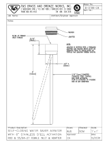
5.35 THROTTLE & CLUTCH LINKAGE
ADJUSTMENT
Throttle Linkage Adjustment
WARNING
!
Remove all tines from tine holders before per-
forming the following linkage adjustments. If
tines are not removed, bystanders may be
injured or the unit may be damaged.
1. Start GA 60 and raise aerator heads to the “UP”
position. Secure the uplatch bar (with heads in “UP”
position) to prevent lowering of heads.
2. Work on adjustable rod with yokes on either end.
Remove the clevis pin at yoke to disconnect the
adjustment rod at pivot connector (See Fig. 15).
1
2
3
4
5 lbs. of Force
(2.26 kg)
Figure 15
1. Adjustable Rod
2. Clevis Pin
3. Fixed Rod
4. Pivot Connector
3. Rotate and push on pivot toward adjustable rod while
pulling on the rod end toward pivot with 5 pounds
(2.26 kg) of force. The distance center to center
between the rod yoke end and pivot connector
should be one inch (25mm). Turn rod yoke in or out
until proper dimensioning is achieved (See Fig. 16).
1”
(25 mm)
1
2
Figure 16
1. Rod End Yoke
2. Pivot Connector
4. Unlatch the uplatch bar and lower the aerating heads
to ease installation of the clevis pin into the yoke and
pivot connector. Secure clevis pin with a new cotter
pin. DO NOT reuse any cotter pins.
Engine Acceleration Timing
5. BE SURE the aerator heads are raised to the “UP”
position.
6. The first point to check is the adjustment of the
throttle rod pin at the control rod. Remove the cotter
pin, two (2) washers and the spring securing the
throttle rod pin to the clutch arm. Observe that one
(1) washer goes on either side of the side of the
spring during reassembly (See Fig. 17).
7. The throttle rod pin should drop into the slot toward
the front of the clutch arm. Adjust pin as necessary
by threading in or out. Secure pin with two (2) original
washers and spring. Retain with a new cotter pin
(See Fig 17).
NOTE: Shortening the control rod will make engine
speed up more quickly when the aerator head is
lowered.
Lengthening the control rod will delay engine
acceleration when the aerator head is lowered.
/