Paxton Easyprox Nano starter kit User guide

Type
User guide

Paxton Easyprox Nano starter kit is a wireless access control system that allows you to control access to your building using key fobs and cards. The system includes a desktop reader for enrolling users, an Easyprox nano lock that can be mounted on a door, and a Net2Air USB dongle for communication between the lock and the PC. The lock can be programmed to grant access to specific users at certain times of the day and can be updated remotely from the PC. The system also features an alarm that sounds if the door is held open for too long or if the battery is low.

Paxton Easyprox Nano starter kit is a wireless access control system that allows you to control access to your building using key fobs and cards. The system includes a desktop reader for enrolling users, an Easyprox nano lock that can be mounted on a door, and a Net2Air USB dongle for communication between the lock and the PC. The lock can be programmed to grant access to specific users at certain times of the day and can be updated remotely from the PC. The system also features an alarm that sounds if the door is held open for too long or if the battery is low.

Page 1
1
1
18/04/2013
Technical Support
Technical help is available: Monday - Friday from 07:00 - 19:00 (GMT)
Saturday from 09:00 - 13:00 (GMT)
01273 811011 [email protected]
Documentation on all Paxton products can be found on our website - http://www.paxton.co.uk/
Ins-30116 Easyprox nano starter kit
The current specication for compatible PC hardware, network and operating systems is
available on our website at the following link: http://paxton.info/720
What's in the box?
Qty
Description
Part Number
Net2 demonstration cards and keyfobs
Documentation
Net2Air USB dongle
Easyprox nano
USB desktop reader
514-326
746-284
Paxton Access
Bench test guide
Paxton
Please go to the following link to download your copy of Net2 Lite software. < http://paxton.info/1438 >
Page 2
sseccA notxaP
Net2 Logon
User name:
OK Cancel
Password:
Log onto Page
Net2
Net2
09:00
Net2 Access
Control
s
P axton Access
T his ba tt er y pack is t o b e
r eplac ed with P ax t on A cc ess
par t numb er 746-003 only .
6V
Identify the parts.
Setting up the PC
Powering up the Easyprox
1 - Front lock assembly
2 - Handle
3 - Net2Air dongle
4 - User tokens
5 - Battery pack
6 - Desktop reader
(underneath main packaging)
1. Plug the dongle into a spare USB port.
2. Plug the desktop reader into a spare USB port.
3. Download the software using the link provided.
4. Run the Net2 application - The Net2 Server 'S' icon
will display in the System tray.
5. Log in to the application - Password = net2
6. Present a token to the Desktop reader.
7. The 'Add user' page will open. - The token number
is displayed in the 'Token number' box.
8. Add a user name and select 'All hours-all doors' as
the access level.
9. Click 'Add user' and 'Close'. The user record will display.
Use this same token through the remaining sections of
this guide.
1. Remove the plastic access plate at the rear of the unit
by removing the top standoff screws.
2. Push the battery pack lead onto the white power plug.
3. Fit the battery pack into the unit and replace and secure
the access plate. - The unit will beep twice.
4. LED Indication - Move your hand over the reader and
the Red LED will ash. This function is used to turn on
the proximity reader to read a token.
5. Slide on the handle and x with the grub screw.
- Moving the handle will now also ash the Red LED.
Battery terminals are located on the base to power the
unit should the internal battery pack fail during service.
The handle is free to move and does not engage with the
lock spindle until access has been granted by presenting a
valid user card.
1
2
3
4
5
6
Page 3
Enrolling the Easyprox
Software TourQ- Click on the following sections in the tree view.
Familiarisation
1. With the Net2 software running, click on the Doors icon to display the Doors screen.
2. Present the user card previously enrolled with the desktop reader to Easyprox.
3. The unit will beep and the LED will ash Blue to show Net2Air communications are taking place.
4. Watch the doors screen. The Easyprox will appear as a new door. Any updates for the lock will
now be transmitted. - Wait for this to complete.
5. If this fails to happen, move the Easyprox closer to the dongle. If you still have problems, please
contact Technical Support.
Doors Q- This lists all the access control units on Net2 with their type and serial number.
Q Double click on the entry and it will show the settings for this door.
Events Q- Present the token to the Easyprox. The LED will briey ash Green and the handle
Q will engage for 3 seconds during which time the unit will beep. The LED will ash Blue
Q during communication with the PC and an entry will appear in the Events Log.
Users Q- Select the user. Click the Tokens tab and you will see the token you have assigned.
Q Click the Events tab. You will see the Events logged so far for this user.
QNet2 software is common across all Paxton control units (Easyprox, Plus, Classic & Nano) and
Qthe screens will self congure to display the relevant data.
1. Update transmissions.
QThe Easyprox is a standalone unit. It checks the PC every hour for updates but is otherwise
Qasleep unless woken up to process a user card for access control. This means that changes made at
Qthe PC are not immediately received by the lock between these hourly update cycles. Updates (except
Qwhen the lock is held open by a timezone) can be forced by using the handle to wake up the unit.
QDisplay the Doors screen and double click the entry. Set the door open time to 10 seconds and apply.
QIf you now touch the handle, the LED will ash Blue as the lock is updated. Presenting a token will now
Qunlock the unit for 10 seconds. Note that if you do not manually call for the update, it would be sent to
Qthe door immediately following the next access control token read or at its hourly update.
QRestore the door open time to 3 seconds using the above procedure.
2. Net2 Server Conguration Utility.
QThis utility is used to view the Net2Air bridge units that are being used by the Net2 software. To view
Qthis information, run the utility program and select Net2Air bridge tab.
QYou will see the Net2Air dongle currently in use. This is the screen that you would use to set up
QNet2Air USB and Net2Air Ethernet bridge units for a larger installation.
3. Software settings - Set up a Door Name.
QDisplay the Doors screen and double click the entry.
QEnter the name of the door in the 'Door Name' box and click Apply. If you now click on the Events tab,
Qyou will see that the 'Where' column now shows the new name against each entry.
4. Lock assembly - LED indications and Alarms.
QHolding the unit in one hand, present the user token and once the LED has ashed Green and the lock
Qhas 'clicked' to engage the handle, lower the handle and hold it down.
QThe unit will attempt to relock after 3 seconds but with the handle held down will fail to do so. The LED
Qwill ash Red while it tries to operate the lock. After 10 seconds, the local alarm will sound and it will
Qpost 'Easyprox cannot lock' in the Events log. Releasing the handle will stop the alarm and lock the
Qdoor. A door relock event will be sent to the PC the next time Easyprox communicates with the server.
Page 4
The following pages contain the full instruction issued with the Easyprox nano.
It includes the following procedures:
- Mounting Easyprox on a door.
- Commissioning.
- Software conguration.
- LED and alarm indications.
- Detailed server operation.
- Battery replacement.
- Flat battery recovery.
The installation requires Net2Air bridge units to achieve the wireless range
necessary for reliable communication. The specication table relates to these
bridge devices.
The Net2Air dongle provided with this kit should not be used for this purpose.
Page 5
Parts list
Tools List
Power Drill
Drill bits 10 mm, 25 mm
Philips screwdriver
Hacksaw for cutting bolts
Hammer / Mallet
Chisel 25 mm
Stanley knife
Adhesive tape
Pencil
Tape measure
8 mm spanner (supplied)
2 mm Allen key (supplied)
1) Front Lock Assembly
2) Rear Lock Assembly
3) Rubber Escutcheon x2
4) Left and Right Handles
5) Battery Pack
6) Tubular Mortice Lock
7) Spindle
8) 8 mm Conversion Sleeve
9) 2 mm Allen Key
10) 8 mm Spanner
11) Strike Plate Backbox
12) Strike Plate
13) Long Mounting Screws x4
14) Short Mounting Screws x4
This unit is for indoor use only.
Ins-30107 Easyprox nano
This wireless unit requires a
Net2Air bridge to communicate
with the server PC.
1
2
6 7
8 9
10 11 12
13
14
3
4
5
Layout
Page 6
Decide on the lock height and mark this on the door.
Fold the template along one dotted line and tape it to
the door with the 'Centreline of Latch' at the required
height. Mark the 4 x 10 mm and 1 x 25 mm holes.
Remove the template, fold along the other dotted line
and apply it to the other side of the door at the same
height. Mark the holes as before.
Remove the access plate at the rear of the unit by
removing the top standoff screws. Push the battery
pack lead onto the white power plug.
Fit the battery pack and replace the access plate.
Installing the hardware
Step 1 - Marking out
Step 2 - Drilling
Step 3 - Fitting the latch
Step 4 - Fitting the battery pack
Drill a 25 mm hole in the door edge at least 80 mm
deep to accept the latch.
Drill the 4 x 10 mm holes for the mounting screws and
one 25 mm hole for the spindle. To ensure accuracy
you should drill these holes from both sides of the
door towards the centre. This also avoids the risk of
damaging the door face when the drill breaks through.
Slide in the latch and draw around the faceplate.
Remove the latch and score the outline with a Stanley
knife to avoid splitting the wood when chiselling.
Chisel a 3.5 mm rebate allowing a ush t for the latch.
Re-t the latch with the plunger facing away from the
door frame and secure with two latch screws.
Cut the spindle to length (Door thickness + 18 mm)
and slide into the latch.
25
57
80
Page 7
Fig A Fig B
Fig C Fig D
Step 5 - Mounting on the door
Step 6 - Fitting the handles
Step 7 - Marking out the strike plate
Step 8 - Fitting the strike plate
Select the short (doors thinner than 45 mm) or long
mounting screws and cut to length if required.
(door thickness + 5 mm)
Fit the rubber escutcheons to the front and back plates.
Present the front and rear lock assembly to the door, locating
the square drive in its recess and join the two parts together
with 4 mounting screws.
Fit the two handles, positioning the screw holes to the
underside and secure with the grub screws provided.
Check the operation of the lock - See Commissioning checks.
Fig A - Vertical position of the strike plate - Close the door and mark the top and bottom position of the
latch horizontally across the frame.
Fig B - Horizontal position of the strike plate - Measure the distance from the back edge of the door to
the at face of the latch. (NOT the plunger.)
Fig C - Mark this distance on the frame to show how far back the plate needs to be to hold the door closed.
Fig D - Position the strike plate within these guide lines. Mark the positions of the xing screws and draw
around the 'cut-out' in the strike plate.
Chisel out a 15 mm aperture to receive the latch bolt.
Fix the strike plate with one latch screw to the surface of the frame.
FROM THE INSIDE: Gently close the door and check that the latch enters the aperture easily with no
additional 'play' in the frame. Small adjustments can be made by moving the plate slightly. When satised,
draw around the outline of the strike plate, remove it. Score around the outline and then cut the rebate to
enable the strike plate to lie ush with the surface.
Fix the strike plate using two latch screws and check the lock operation. Remove the strike plate and
increase the aperture to accept the strike plate backbox. Now re-x the strike plate and check the operation
of the 'anti-shim' plunger and the door.
The unit is now fully operational and should be enrolled as soon as possible to preserve battery life.
Page 8
The current specication for compatible PC hardware, network and operating systems is available on our website
at the following link: http://paxton.info/720
There is NO Net2 Easyprox detection function. It is recognised that there could be security issues if the
wireless units were detectable from outside the site. During installation, an Easyprox unit binds to a Net2Air
bridge which will then only talk to registered units. The Server Conguration Utility also has an ' Enable
commissioning' mode which can be turned off to inhibit other units being added.
An entry is then made on the Doors screen and a special icon is used to denote the wireless connection.
With the product xed securely to the door:
1) Extend the door open time by changing this door's settings on the Net2 PC. Set ' Door open time' to 20
seconds and then present a user card at the door. Before each check, present a user card to unlock the door.
2) Check that the handles are running smoothly, this is best done by depressing the handle all the way to the
bottom and then releasing it as slowly as possible, if the handle is left behind at any point it is likely that the
product has not been installed squarely enough. Check the handle on both sides of the door.
3) If your nger is able to leave the handle, remove the Easyprox from the door (or slacken the four xing
screws) and see if the problem goes away. If it does, then the installation onto the door is at fault and the drilling
of the mounting holes should be checked for alignment.
4) Once the install has successfully passed this test return the door to normal operation by changing the PC
setting for this door back to its previous door open time (default 3 seconds) and present a user card.
This test conrms the correct and free operation of the mechanical lock and also ensures that the electronic
circuits will shut down correctly preserving battery life.
Commissioning checks
An Easyprox must bind to a Net2Air bridge before it will enrol itself onto the Net2 system. The term 'bind' is
used to denote the xed relationship between a wireless unit and its bridge.
1. Create a user record in the database and assign a Net2 token to the user. This record can be deleted after
the installation is complete.
2. You must now wake up the Easyprox. This can be achieved by either raising your hand to be detected by the
PIR or moving the handle.
3. Present the same user token to the Easyprox which will then transmit the token number and wait for a
response from a bridge.
The software has the 'Enable commissioning mode' set as a default. If this has been turned off in the Server
Conguration Utility, it must be enabled for this process to succeed.
If more than one bridge replies, the Easyprox checks the signal strength and selects the strongest bridge to
communicate with. The Net2 software conrms that the token number is in the database and if so registers this
Easyprox/bridge binding.
Enrolling an Easyprox
The Net2 software should be loaded on the controlling PC and at least one Net2Air bridge congured to
communicate with the unit.
Full documentation is supplied with the Net2Air bridge unit and also on the website as follows:
XAN1051 - Installing Net2 software < http://paxton.info/1520 >
XIns-30084 - Net2Air USB bridge < http://paxton.info/926 >
XIns-30085 - Net2Air Ethernet bridge < http://paxton.info/920 >
Software installation
Download the latest version of Net2 software at: http://paxton.info/1438 before commissioning this product.
The Blue LED will now ash for several minutes while its software is updated to match the current Net2 version.
Page 9
Presenting a valid user token to the unit will cause the LED to briey ash Green and the door will unlock.
The presentation of a barred or unknown user token is indicted by a Red LED display.
The external handle is only engaged once access has been granted. The inside handle is always engaged.
Normal Operation
A button on the inside allows the internal handle to be held in the unlocked position.
Software Conguration
Name: The reader can be named individually if required.
Reader operating mode: Set the operating mode.
Timed operating modes: A different operating mode can
be congured within a time window.
Reader: Local settings for the reader.
Output: Congures the lock for timed release or toggle mode.
Events: Shows the events for this control unit only.
Access Rights: Lists users who have access through this door.
Door name: Name the Door.
Door open time: Set the door open time.
Unlock the Door during: Holds the door
unlocked during this timezone. - Set to 'At No
Time' for normal user operation.
Blue
Green ash + beep
Red ash + low beep
Red ash
Amber constant ashing
Red constant ashing
Indicates wireless communication with the Net2 software
A valid user card has been presented and the handle is engaged
An invalid user card has been presented - No access granted
Activity has been sensed but no user card has been presented
A valid user card has been presented - the handle is not horizontal and so the latch cannot release
The handle is being held down - The latch cannot relock
LED indications
Page 10
Easyprox reset
The Easyprox holds address information for the bridge that it is bound to. This will cause problems if the unit is to
be used on another system.
The unit requires a hardware reset to clear its bridge information. This is achieved as follows:
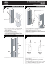
1. Remove the unit from the door by removing the 4 mounting screws on the rear lock assembly.
2. Remove the access plate at the rear of the front lock assembly (top two standoff screws).
3. Locate the reset push button at the lower right corner of the circuit board.
4. Hold the button down and wake up the unit by briey depressing the handle. The unit will give a single beep.
5. Push the reset button 4 more times and the unit will beep 5 times and display an AMBER LED.
6. Replace the access plate.
7. Enrol the unit - as above.
8. Ret the lock to the door with the 4 mounting screws.
The access control unit connects to the Net2 system using Paxton Net2Air proprietary wireless technology through
a Net2Air bridge.
Radio signals do not always behave as you might expect. For example, a mobile phone that displays a full signal
on one part of the site will lose signal completely only a few metres away.
See also: XAN1095 - Net2 wireless access control - How does it work? < http://paxton.info/974 >
X AN1096 - How to plan a Net2 wireless installation < http://paxton.info/975 >
The Easyprox is a standalone unit and stays asleep while there is no user activity. The Net2 server cannot wake
up the unit. If the PIR is activated or the handle moved, it powers up the reader circuits in readiness for a token
read. Should nothing occur within 3 seconds, the unit will go back to sleep.
If a token is read, then the Easyprox moves into full operation. The token number is checked against the stored
database and access is granted or denied as per a standard Net2 control unit.
The Easyprox now sends this data via its Net2Air bridge connection to the Net2 server software. If any updates
need to be sent to the unit, including changes to the user data, these are now transmitted back. The unit will
then go back to sleep again waiting for further activity.
After 1 hour of inactivity, the unit will send a heartbeat to the Net2 PC which responds with any updates, as
above. This keeps the Easyprox updated even when there is no activity at the door. The 1 hour delay is mitigated
by the vastly increased battery life in each unit and the fact that any user activity (card read or handle use) will
also cause an immediate update to be made. It therefore follows that a new user may need to trigger an update
before being given access through a door.
Easyprox / server operation
Net2Air wireless communication
Radio frequency
This product should not be installed within 3 metres of other wireless equipment operating on a 2.4Ghz frequency.
To ensure optimum performance other wireless networks should avoid WiFi channels 11, 12 and 13 to reduce the
possibility of interference.
Some of the Net2 features (e.g. Fire alarm integration, Anti-passback, Lockdown) are not available on this product
as wireless communication is not suitable for data critical applications.
During the 1 hour sleep period, any changes made at the PC will not be received. If an immediate update
is required, the unit must be woken up by pressing the front button or presenting a user card.
Where a door is held unlocked by software, it will still receive updates every hour. To force an
immediate update, the unit must by activated by pressing the front button. A card can then be
presented to initiate the update request.
Page 11
Battery replacement
1. Remove the unit from the door by removing the 4 securing screws on the rear lock assembly.
2. Remove the top two standoff screws - Fig 1.
3. Remove the access plate to reveal the battery pack. - Fig 2.
4. Unplug the lead and replace the pack with a new Paxton battery pack. - Fig 3.
(The unit will retain its settings and should not be manually reset).
5. Ret the access plate and secure.
6. Ret the unit to the door.
Fig 1
Fig 2
Fig 3
Recovery from a at battery
Should the battery pack become discharged, the latch will no longer function.
This could be in the locked or unlocked state.
Holding a PP3 9V battery up to the contacts on the bottom of the unit will allow
the circuitry to operate normally.
A valid user card can then be used to open the door to access the batteries.
+ve-ve
When the battery voltage falls below 4V, the user will see a delay between the card being read and access being
granted. This delay provides a warning that the battery pack should be replaced.
The warning delay starts at 2 seconds, increasing up to 10 seconds as the battery discharges with use.
Low battery warning
Alarm Sounder
The alarm is activated when the door fails to re-lock itself. The alarm will sound for 60 seconds during which time
the unit will try to lock the door once every 10 seconds. After 60 seconds the unit will then shut down. When
the unit is woken up, it will immediately try to lock the door. If it fails, the alarm cycle will start again. Failure to
relock will substantially reduce battery life.
Page 12
10,000
250
64
1 sec 99,999 sec
10
100
20 m
4,096
50 mm 30 mm
0 °C + 55 °C
60 mm 194 mm 30 mm
150 mm 194 mm 72 mm
Operating temperature - Battery limits
Environment
Dimensions
Features
Waterproof
Min
Width
Height
Max
Depth
Min
Max
Access levels
Time zones
Maximum door open time
ACU's per Net2Air bridge - Recommended
Events stored in ACU with no server connection
Number of Cards
Specications
No
Net2Air bridge per system
Net2Air wireless range
The declaration of conformity is available on request. Contact details are provided at: http://paxton.info/596
30,000 operations
Paxton Battery Pack
Low
Reader/Keypad module (required space on door)
Total outside dimensions (includes handle clearance)
Battery type - High capacity (746-003)
Typical battery life
Vandal resistance
Read Range
Keyfob
Token
This product is not suitable for retail sale. All warranties are invalid if this product is not installed by a competent person.
  • Page 1 1
  • Page 2 2
  • Page 3 3
  • Page 4 4
  • Page 5 5
  • Page 6 6
  • Page 7 7
  • Page 8 8
  • Page 9 9
  • Page 10 10
  • Page 11 11
  • Page 12 12

Paxton Easyprox Nano starter kit User guide

Type
User guide

Paxton Easyprox Nano starter kit is a wireless access control system that allows you to control access to your building using key fobs and cards. The system includes a desktop reader for enrolling users, an Easyprox nano lock that can be mounted on a door, and a Net2Air USB dongle for communication between the lock and the PC. The lock can be programmed to grant access to specific users at certain times of the day and can be updated remotely from the PC. The system also features an alarm that sounds if the door is held open for too long or if the battery is low.

Ask a question and I''ll find the answer in the document

Finding information in a document is now easier with AI