Page is loading ...

Latest Revision: 02.02.2005
Document Ref.: 1010.D.01.00136_8
Product Code: CP72SR5
D3, D5, A5
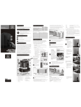
SLIDING GATE
AUTOMATION
INSTALLATION
MANUAL


MAJOR COMPONENTS (TYPICAL D5 SHOWN)
- COVER
- CONTROLLER (CP80 FOR D3/D5; CP81 FOR A5)
- MOTOR (12V DC FOR D3/D5; 220V AC FOR A5)
- BATTERY (12V DC, 7A/H-D3/D5 ONLY) (OR PSU1/2, IF FITTED)
- CHARGER TRANSFORMER/POWER SUPPLY (CP84E for D3/D5
or CP83E for A5) (NOT FITTED WHEN PSU1/2 IS USED).
- GEARBOX CASING
- INTERNAL LIMIT SWITCH (DOSS)
- MANUAL RELEASE THUMBWHEEL
- LOCKABLE ACCESS DOOR
1
0
3
31
32
33
34
35
36
73
38
36
38
34
30
31
32
33
35
37
I
O
L
LLEVE
WARNING! (D5/A5 ONLY)
Fill with oil prior to running
gearbox.
NB. D3 is pre-filled with
fluid grease.
1. Lift off the cover to the
operator.
2. Remove the control card
and battery so that you
can gain access to the
filler plug.
3. Unscrew the cap and
pour in the oil provided
For transport purposes this
unit has been supplied with
oil in a separate sealed
container.
Oil Specifications:
GRADE: 75W90
Qty: 75ml
IMPORTANT

D3
GATE MASS (kg)
RUN (kgF)
TABLE 1
START (kgF)
25 12 300
D5
60 20 500
D5 Light Industrial
16*
16*
500
A5
*LIMITED BY CAPACITY OF PSU
22 22 500
2

ANTI-LIFT BRACKETS
- Guide rollers must ensure that the gate is held vertically.
- Fit suitable anti-lift brackets . The gap should be <5mm to ensure
the gate cannot be lifted off the motor pinion.
- For improved safety fit additional support post to prevent gate from
falling over if guide rollers fail.
3
39
39
42
40
41

D5
*
6
36
41
48
56
67
81
100
8
10
12
14
16
18
20
22
24
26
28
30
Pull ( kgf )
Duty Cycle ( % )
A5 with FAN
5
15
20
30
25
80
20
0
0
100
40
120
60
Time (hrs)
Duty Cycle ( % )
A5
5
15
20
30
25
80
20
100
40
120
60
Time (hrs)
Duty Cycle ( % )
DUTY CYCLE CURVES
- FOR THE WARRANTY TO BE VALID, ENSURE THAT THE DUTY CYCLE
IS NOT EXCEEDED FOR THE PARTICULAR MOTOR BEING USED.
* - DUTY CYCLE IS SUBJECT TO BATTERY AND CHARGER SIZE.
4

9
8
10
6
5
7
3
4
5
† For cable types to be used (e.g. SWA, Cabtyre, Intercom cable etc.) consult your
municipal authority for details.
* n1 = NUMBER OF CORES REQUIRED BY INTERCOM
# n2 = NUMBER OF CORES REQUIRED BY INTERCOM
‡ sufficient for motor only, increase to suit total load if pillar lights are fitted
RECOMMENDED INSTALLATION AND
†
CABLE THICKNESS REQUIREMENTS
- LOCAL ISOLATOR
- MAINS SUPPLY (min 0.5mm² ‡, 2 CORE + EARTH)
- INTERCOM AND STATUS SIGNALING TO HOUSE
(0.2mm², *n1 + 6 CORE)
- INTERCOM TO GATE STATION (0.2mm², #n2 CORES)
- PILLAR LIGHTS (0.5mm², 2 CORE + EARTH)
- RADIO RECEIVER (0.2mm², 3 CORE)
- PEDESTRIAN KEYSWITCH (0.2mm², 2 CORE)
- INFRA RED BEAM (0.2mm², 3 CORE)
- FREE EXIT LOOP (1.5mm², multi stranded cable)
- FREE EXIT CONTACT (0.2mm², 2 CORE)
3
2
4
5
6
7
8
9
10
11
11
2

6
MECHANICAL MOUNTING DETAILS
Option 1 - Bolt down onto concrete plinth
- Ensure motor does not protrude into drive-way install baseplate
with centre line 250mm off pillar centre.
- Position baseplate (43) with centre of single support stud (45) 105mm
from edge of gate (46). (This dimension assumes centre line of rack (47)
is 20mm from edge of gate).
- Using the baseplate as a template mark and drill the 4 mounting holes
into the concrete for the four M10 x 95 expansion studs.
- Use two M12 plated nuts per expansion stud as spacers below the
foundation plate.
- Secure the baseplate to the expansion studs using one M10 washer and
nut per expansion stud.
105mm
20mm
4545
4343 4747 4646
L
C

7
2 m5
0m
L
C
M10 Nut
Use two M12 plated
nuts as spacers.
M10 Washer
M10 x 95 expansion stud
Existing concrete plinth

- Ensure motor does not protrude into drive-way install baseplate
with centre line 250mm off pillar centre.
- Fasten concrete anchors (44) to the baseplate (43) using the M10x45
bolts provided. Ensure that the bolts are well tightened.
- Position baseplate (43) with centre of single support stud (45) 105mm
from edge of gate (46). (This dimension assumes centre line of rack (47)
is 20mm from edge of gate).
8
105mm
20mm
4545
4343 4747 4646
L
C
4444
4343
m
25
0
m
4444
L
C
04
m
0 m
400mm
300mm
MECHANICAL MOUNTING DETAILS
Option 2 - Set into concrete plinth

PROVISION FOR CABLES
- Ensure cables are fitted through base plate before concreting
in place.
- Remove knock-outs from gearbox to allow for cable entry.
- Route cables in front of battery (D3/D5 motors) as shown above.
- Seal cable entry holes with silicone sealer.
9
47
46 43
47
350 mm
30 mm
46
43

GEARBOX MOUNTING DOWN DETAILS
- Leave at least 7mm clearance between the lower gearbox nuts and
the baseplate to allow for later adjustment.
- Gearbox MUST be firmly located between top & bottom nuts and washers
as shown at . Use spring washer to lock top nut in place.
- Slide gearbox forwards or backwards to give ±8mm clearance between
front of pinion and edge of gate.
7
mm
53
10
52
54
51
52
54 51 53
54

MOUNTING RACK
- Attach steel rack to gate using 25x25x2mm angle brackets . Distance
between centerline of rack and edge of gate should be 20mm (see ).
- For best results support rack every 300mm.
- Rack must be mounted level with a 2 - 3mm clearance .
56
55
57
11
55
56
57
±300 mm
l
Raise gearbox by an additional 3mm.
l
Put gearbox into manual mode
(see on page 22)
l
Mesh rack and pinion fully and mount rack.
Slide gate backwards and forwards
ensuring that rack mesh is smooth and
never tight.
l
Drop gearbox by 3mm to create 3mm tooth
clearance.
........
USEFUL TIP
37

MOUNTING RACK CONTINUED
200 - 300mm
LEVEL
200mm
58
60
59
12
- A simple way of ensuring correct pitch spacing when joining steel rack is
to clamp a small offcut between the two pieces.
- Check that weld does not foul with meshing surfaces.
- If RAZ ™ rack is used, then start installing from the right hand side of
the gate working towards the LHS. Use fastening screws e.g. “TEK” screws
at least every 200mm.
58
59
60

INSTALLING CHAIN DRIVE SYSTEMS
- Weld rear anchor plate onto gate such that centre line of tensioner
pin is in line with top of the shaft on the idler pulley . Allow at least
100mm between idler pulleys and anchor brackets.
- Align fixed anchor bracket as for .
- Ensure chain direction over sprocket is as shown (see ).
IDLER
PULLEYS
13
>100mm
>100mm
64
65
62
61
63
61
63 61
65
6462

SETTING MECHANICAL CLUTCH (A5 ONLY)
- Isolate MAINS POWER.
- Remove fan from motor to expose the motor shaft (where applicable).
Ensure fan has stopped turning.
- Lock shaft using 13mm spanner and use 6mm allen key to adjust
sensitivity - Clockwise to increase force.
- Recommended maximum push force should not exceed 15kgF.
13mm
6mm
14
<15kgF

15
- With the gate in the CLOSED position, mount the origin marker (66) a minimum
500mm from the origin sensor (68). (See isometric view (A) or plan view (B)
above).Please note this distance will affect the pedestrian opening distance. For
minimum pedestrian opening, mount the origin marker at 500mm. The
maximum distance of the origin marker is limited by the marker having to pass
the sensor by no less than 500mm before the gate opens fully. If a longer
crawling distance is required, the position of the marker needs to be changed
(see table 3 on page 30).
- Manually slide gate OPEN until origin marker (66) is in line with the origin
sensor (68). Ensure distance between face of marker (66) and front face of
sensor (68) is between 13 and 20mm. (See (C) above)
- Adjust distance by sliding the origin marker (66) along the slotted mounting
holes until desired distance is achieved.
MOUNTING OF GATE SENSOR
66
B
CC
A
66
68
R TE THAN
5 0mm
G EA R 0
MOUNTING CONFIGURATION
FOR STEEL RACK
ORIGIN MARKER
BRACKET
WELD
MOUNTING
BRACKET
PROVIDED TO
STEEL RACK
BOLT USING
FASTENERS
PROVIDED
66
66
13-20mm
GREATER THAN 500mm
68

POWER WIRING (SEE PAGE 15 FOR SIGNAL WIRING)
16
- 220V AC MOTOR WITH STARTING CAPACITOR
- 220V AC, 1Ø, MAINS SUPPLY FOR CP84E / CP83E USING
REMOVABLE CONNECTORS
- CP83E POWER SUPPLY TRANSFORMER (A5 MODEL ONLY)
- 220V AC PILLAR LIGHT (NOT AVAILABLE ON CP84XTE PSU)
- 12V DC MOTOR
- 12V DC LEAD ACID BATTERY (Amp/HOUR RATING TO SUIT)
- CP84E CHARGER TRANSFORMER (D3/D5 MODEL)
(OR CP84XTE WHEN USED WITH PLUG-IN TRANSFORMER)
- LIGHTNING EARTH POINT
- 12V DC PLUG TO CP81 CONTROLLER
- 14.2V DC CHARGE PLUG TO CP80 CONTROLLER
- PSU1/2 - POWER SUPPLY UNIT
- MAINS FUSE - PSU1/2
NOTE: External battery not necessary but if fitted then CP80 PSU1
*
controller must be fitted.
*
12
13
14
15
16
17
18
19
20
21
75
76
L
N
E
1212
13
15
20
M1
M3
L
BROWN
BLUE
GREEN/YELLOW
LIGHT COMN EM2
CP81
19
14
NN
LL
EE
L
N
E
L
N
E
13
15
21
16
19
LIGHT
LIGHT
MOTOR
MOTOR
BATT -
BATT +
COM
17
M
CP80
NN
LL
EE
18
15
16
LIGHT
LIGHT
MOTOR
MOTOR
BATT -
BATT +
COM
17
M
CP80 PSU1
*
21
L
N
E
13
76
75
BATT -
BATT +

SIGNAL WIRING (CP80 AND CP81)
COM
COM
NEG
NEG
NEG
22
23
24
25
26
27
28
29
N/C
N/O
12V
12V
12V
17
- RADIO RECEIVER (OR OTHER TRIGGER e.g. INTERCOM)
- INFRA RED BEAM TRANSMITTER
- INFRA RED BEAM RECEIVER (N/C CONTACT)
- FREE EXIT TRIGGER (N/O CONTACT)
†
- REMOTE STATUS LED (MAX 3 IN PARALLEL)
- PEDESTRIAN TRIGGER (N/O CONTACT)
- HOLIDAY LOCKOUT CONTROL (N/C LATCHING CONTACT)
- REMOTE PILLAR LIGHT CONTROL (N/O CONTACT)
LIGHT
LIGHT
COM
COM
+12V
TRG
IRB
FRX
LED
LCK
PED
SET
= LED INDICATORS ON P.C.B. SHOWING STATUS OF INPUT SIGNALS
† = USE MULTI LED DRIVER CARD (CP78) FOR MORE LED’S
CP80 / CP81
2
2
23
24
52
62
27
28
29

RECOMMENDED LIGHTNING PROTECTION
18
- For optimum lightning protection ensure earth cable from charger/PSU unit
is adequately earthed.
- Use ring lug to bond to baseplate mounting stud.
- For additional protection bond baseplate to earth spike .
- In event of damage to charger/PSU unit disconnect quick release link
and push-on connector on controller.
L
N
E
220V AC OUTPUT
220V AC
INPUT
TO CP80/CP81
PCB "DC IN”
LNE
48
43
34
31
50
34
49
48
50
43
34
49
/