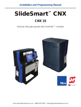
Centurion A10 Series Programming Manual

Type
Programming Manual

Centurion A10 Series is a heavy-duty industrial sliding gate operator designed for gates up to 2,300 lbs. It features automatic setup, soft start and stop, adjustable auto-close, collision sensitivity, pedestrian opening, and more. The A10 Series is ideal for commercial and industrial applications, including warehouses, factories, and parking lots.

Centurion A10 Series is a heavy-duty industrial sliding gate operator designed for gates up to 2,300 lbs. It features automatic setup, soft start and stop, adjustable auto-close, collision sensitivity, pedestrian opening, and more. The A10 Series is ideal for commercial and industrial applications, including warehouses, factories, and parking lots.

A10 operating programming guide
INDUSTRIAL
SLIDING GATE
OPERATOR
Pre-programming considerations:
When the gate is in the CLOSED position the sensor magnet should be at least 500mm from the sensor. The
gap between the sensor and the magnet must be between 13 - 20mm. The arrow on the magnet must point
in the direction of the sensor.
Ensure that effective end stops have been installed at both ends of the gate.
Ensure all interconnecting cables are securely in place (see Fig. 1 & 2).
Ensure single phase mains power is connected to the inverter (see Fig 2)
Disengage the Manual Release lever and move the gate to the middle of travel. Re-engage the Manual Release
lever.
Programming Mode:
Position Set link over both Set Pins.
Press and release the RESET button. The STATUS light will flash 5 times. The SET and L2 lights will now be on.
You are now in Programming Mode
Automatic set-up routine:
Press and hold the TEST pushbutton for 1 flash of L1, and then release. L2 will go off, and L1 will flash once
per second.
Determine right or left hand opening (as viewed from the release handle side of the motor).
Press and hold the TEST button, while monitoring the STATUS light.
Release the TEST button after ONE flash if gate opens to the right, or TWO Flashes if gate opens to the left.
The gate will begin to slowly open.
The gate will slowly open until it hits the open end stop, then slowly close until it hits the closed end stop.
The gate will then open at normal speed until the magnet passes the origin, and then slowly open until it hits
the open end stop.
The gate will then close at normal speed until the magnet passes the origin and then continue to close
slowly until it hits the closed end stop.
The gate will then open at normal speed until it reaches the minimum pedestrian opening position. If a
wider pedestrian opening is required, jog the gate further open by shorting the PED input to COM. When
the correct position is reached, press the TEST button.
The STATUS light will flash 5 times, and L2 will light up. The gate limits have now been set.
If no additional Features are required, then exit programming mode by removing the SET link. Store the link by
pushing it over ONE of the two pins.
Open and close the gate a few times to check operation.
A10 OPERATOR PROGRAMMING GUIDE
Ensure controller is in programming mode (SET and L2 are ON).
Press and hold the TEST button. L1 will start flashing. When L1 flashes twice release the TEST
push button.
Press TEST button and wait until the STATUS LED flashes once.
Release TEST button.
AUTO CLOSE TIME is now ON and set to 15 seconds (Factory default).
Remove the SET link from the set jumper and store the link on one of the pins of the jumper, if
you want to exit program mode.
Ensure that the controller is in programming mode (SET and L2 are ON).
Press and hold TEST button. L1 starts flashing. When L1 flashes three times release the TEST
push button (One flash of STATUS is equal to one second of auto-close time).
Release the TEST button after the STATUS LED has flashed the required number of times.
AUTO CLOSE TIME is now set.
Remove the SET link from the set jumper and store the link on one of the pins of the jumper, if
you want to exit the program mode.
Ensure the controller is in programming mode (SET and L2 are ON).
Press and hold the TEST button.
L1 starts flashing; after 7 flashes release TEST button and L2 will go OFF.
Press TEST button and wait for STATUS to flash;
1 flash = High sensitivity (Gate stops easily)(Default setting)
2 flashes = Medium sensitivity (Gate stop with reasonable effort)
3 flashes = Low sensitivity (Gate stops with difficulty)
Release the TEST button after required number of flashes.
L2 will go ON.
COLLISION SENSITIVITY is set; remove the SET link from the set jumper and store the link on
one of the pins of the jumper, if you want to exit program mode.
AUTO CLOSE
AUTO CLOSE TIME
COLLISION SENSITIVITY
Figure 1 A10 Cable Routing
SIGNAL CABLE
TO CONTROLLER
Figure 2 A10 Cable Interconnections
PILL
AR / COUR
TESY
LIGHT (POTENTIAL FREE)
(MAX 400W)
OPTIONAL F
AN
ENCODER
SENSOR
ORIGIN
SENSOR
CP201
CONTROLLER
CP200
INVERTER
T
o optional
DC converter
L
N
E
FROM OPTIONAL
DC CONVER
TER
TO PILL
AR
LIGHTS
FROM AC
MAINS
0.07.A.0123_22072013
www.centsys.com
  • Page 1 1
  • Page 2 2
  • Page 3 3
  • Page 4 4

Centurion A10 Series Programming Manual

Type
Programming Manual

Centurion A10 Series is a heavy-duty industrial sliding gate operator designed for gates up to 2,300 lbs. It features automatic setup, soft start and stop, adjustable auto-close, collision sensitivity, pedestrian opening, and more. The A10 Series is ideal for commercial and industrial applications, including warehouses, factories, and parking lots.

Ask a question and I''ll find the answer in the document

Finding information in a document is now easier with AI