Page is loading ...

7X 8X 9X 10X 11X 12X1X 2X 3X 4X 5X 6X
ESX-1320
COM 2 COM 1
DISPLAY RESET
MULTI PORT ETHERNET SWITCH
WITH FDSE
™
AND LANVIEW
®
PWR
CPU
RECEIVE
TRANSMIT
PORT
1234 56789101112
BRIM-A100
STY
LNK
XMT
RCV
ESX-1380
COM 2 COM 1
DISPLAY RESET
MULTI PORT ETHERNET SWITCH
WITH FDSE
™
AND LANVIEW
®
PWR
CPU
RECEIVE
TRANSMIT
PORT
1234 56789101112
BRIM-A100
STY
LNK
XMT
RCV
PORT 12
TXRX
PORT 11
TXRX
PORT 10
TXRX
PORT 9
TXRX
PORT 8
TXRX
PORT 7
TXRX
PORT 6
TXRX
PORT 5
TXRX
PORT 4
TXRX
PORT 3
TXRX
PORT 2
TXRX
PORT 1
TXRX
ESX-1320/ESX-1380
INSTALLATION GUIDE


ESX-1320/ESX-1380 Installation Guide i
NOTICE
Cabletron Systems reserves the right to make changes in specifications and other information
contained in this document without prior notice. The reader should in all cases consult Cabletron
Systems to determine whether any such changes have been made.
The hardware, firmware, or software described in this manual is subject to change without notice.
IN NO EVENT SHALL CABLETRON SYSTEMS BE LIABLE FOR ANY INCIDENTAL,
INDIRECT, SPECIAL, OR CONSEQUENTIAL DAMAGES WHATSOEVER (INCLUDING BUT
NOT LIMITED TO LOST PROFITS) ARISING OUT OF OR RELATED TO THIS MANUAL OR
THE INFORMATION CONTAINED IN IT, EVEN IF CABLETRON SYSTEMS HAS BEEN
ADVISED OF, KNOWN, OR SHOULD HAVE KNOWN, THE POSSIBILITY OF SUCH
DAMAGES.
Copyright 1996 by Cabletron Systems, Inc., P.O. Box 5005, Rochester, NH 03866-5005
All Rights Reserved
Printed in the United States of America
Order Number: 9031574-03 November 1996
SecureFast Switch
,
SPECTRUM
,
LANVIEW
,
MicroMMAC
, and
BRIM
are registered
trademarks and
Element Manager
,
EPIM
,
EPIM-A
,
EPIM-F1
,
EPIM-F2
,
EPIM-F3
,
EPIM-T
,
EPIM-X
,
ESX-1320
,
ESX-1380
,
FOT-F
,
FOT-F3
,
HubSTACK
,
SEH
,
SEHI
, and
TMS-3
are
trademarks of Cabletron Systems, Inc.
All other product names mentioned in this manual may be trademarks or registered trademarks of
their respective companies.
FCC NOTICE
This device complies with Part 15 of the FCC rules. Operation is subject to the following two
conditions: (1) this device may not cause harmful interference, and (2) this device must accept any
interference received, including interference that may cause undesired operation.
NOTE:
This equipment has been tested and found to comply with the limits for a Class A digital
device, pursuant to Part 15 of the FCC rules. These limits are designed to provide reasonable
protection against harmful interference when the equipment is operated in a commercial environment.
This equipment uses, generates, and can radiate radio frequency energy and if not installed in
accordance with the operator’s manual, may cause harmful interference to radio communications.
Operation of this equipment in a residential area is likely to cause interference in which case the user
will be required to correct the interference at his own expense.
WARNING:
Changes or modifications made to this device which are not expressly approved by the
party responsible for compliance could void the user’s authority to operate the equipment.
Only qualified personnel should perform installation
procedures.
Printed on Recycled Paper

Notice
ii ESX-1320/ESX-1380 Installation Guide
DOC NOTICE
This digital apparatus does not exceed the Class A limits for radio noise emissions from digital
apparatus set out in the Radio Interference Regulations of the Canadian Department of
Communications.
Le présent appareil numérique n’émet pas de bruits radioélectriques dépassant les limites applicables
aux appareils numériques de la class A prescrites dans le Règlement sur le brouillage radioélectrique
édicté par le ministère des Communications du Canada.
VCCI NOTICE
This equipment is in the 1st Class Category (information equipment to be used in commercial and/or
industrial areas) and conforms to the standards set by the Voluntary Control Council for Interference
by Information Technology Equipment (VCCI) aimed at preventing radio interference in commercial
and/or industrial areas.
Consequently, when used in a residential area or in an adjacent area thereto, radio interference may be
caused to radios and TV receivers, etc.
Read the instructions for correct handling.
CABLETRON SYSTEMS, INC. PROGRAM LICENSE AGREEMENT
IMPORTANT:
Before utilizing this product, carefully read this License Agreement.
This document is an agreement between you, the end user, and Cabletron Systems, Inc. (“Cabletron”)
that sets forth your rights and obligations with respect to the Cabletron software program (the
“Program”) contained in this package. The Program may be contained in firmware, chips or other
media. BY UTILIZING THE ENCLOSED PRODUCT, YOU ARE AGREEING TO BECOME
BOUND BY THE TERMS OF THIS AGREEMENT, WHICH INCLUDES THE LICENSE AND
THE LIMITATION OF WARRANTY AND DISCLAIMER OF LIABILITY. IF YOU DO NOT
AGREE TO THE TERMS OF THIS AGREEMENT, PROMPTLY RETURN THE UNUSED
PRODUCT TO THE PLACE OF PURCHASE FOR A FULL REFUND.

Notice
ESX-1320/ESX-1380 Installation Guide iii
CABLETRON SOFTWARE PROGRAM LICENSE
1. LICENSE
. You have the right to use only the one (1) copy of the Program provided in this
package subject to the terms and conditions of this License Agreement.
You may not copy, reproduce or transmit any part of the Program except as permitted by the
Copyright Act of the United States or as authorized in writing by Cabletron.
2. OTHER RESTRICTIONS. You may not reverse engineer, decompile, or disassemble the
Program.
3. APPLICABLE LAW. This License Agreement shall be interpreted and governed under the laws
and in the state and federal courts of New Hampshire. You accept the personal jurisdiction and
venue of the New Hampshire courts.
EXCLUSION OF WARRANTY AND DISCLAIMER OF LIABILITY
1. EXCLUSION OF
WARRANTY. Except as may be specifically provided by Cabletron in
writing, Cabletron makes no warranty, expressed or implied, concerning the Program (including
its documentation and media).
CABLETRON DISCLAIMS ALL WARRANTIES, OTHER THAN THOSE SUPPLIED TO
YOU BY CABLETRON IN WRITING, EITHER EXPRESSED OR IMPLIED, INCLUDING
BUT NOT LIMITED TO IMPLIED WARRANTIES OF MERCHANTABILITY AND
FITNESS FOR A PARTICULAR PURPOSE, WITH RESPECT TO THE PROGRAM, THE
ACCOMPANYING WRITTEN MATERIALS, AND ANY ACCOMPANYING HARDWARE.
2. NO LIABILITY FOR CONSEQUENTIAL DAMAGES. IN NO EVENT SHALL
CABLETRON OR ITS SUPPLIERS BE LIABLE FOR ANY DAMAGES WHATSOEVER
(INCLUDING, WITHOUT LIMITATION, DAMAGES FOR LOSS OF BUSINESS,
PROFITS, BUSINESS INTERRUPTION, LOSS OF BUSINESS INFORMATION, SPECIAL,
INCIDENTAL, CONSEQUENTIAL, OR RELIANCE DAMAGES, OR OTHER LOSS)
ARISING OUT OF THE USE OR INABILITY TO USE THIS CABLETRON PRODUCT,
EVEN IF CABLETRON HAS BEEN ADVISED OF THE POSSIBILITY OF SUCH
DAMAGES. BECAUSE SOME STATES DO NOT ALLOW THE EXCLUSION OR
LIMITATION OF LIABILITY FOR CONSEQUENTIAL OR INCIDENTAL DAMAGES, OR
ON THE DURATION OR LIMITATION OF IMPLIED WARRANTIES, IN SOME
INSTANCES THE ABOVE LIMITATIONS AND EXCLUSIONS MAY NOT APPLY TO
YOU.
UNITED STATES GOVERNMENT RESTRICTED RIGHTS
The enclosed product (a) was developed solely at private expense; (b) contains “restricted computer
software” submitted with restricted rights in accordance with Section 52227-19 (a) through (d) of the
Commercial Computer Software - Restricted Rights Clause and its successors, and (c) in all respects
is proprietary data belonging to Cabletron and/or its suppliers.
For Department of Defense units, the product is licensed with “Restricted Rights” as defined in the
DoD Supplement to the Federal Acquisition Regulations, Section 52.227-7013 (c) (1) (ii) and its
successors, and use, duplication, disclosure by the Government is subject to restrictions as set forth in
subparagraph (c) (1) (ii) of the Rights in Technical Data and Computer Software clause at
252.227-7013. Cabletron Systems, Inc., 35 Industrial Way, Rochester, New Hampshire 03867-0505.

Notice
iv ESX-1320/ESX-1380 Installation Guide
DECLARATION OF CONFORMITY
Application of Council Directive(s):
89/336/EEC
73/23/EEC
Manufacturer’s Name:
Cabletron Systems, Inc.
Manufacturer’s Address:
35 Industrial Way
PO Box 5005
Rochester, NH 03867
European Representative Name:
Mr. J. Solari
European Representative Address:
Cabletron Systems Limited
Nexus House, Newbury Business Park
London Road, Newbury
Berkshire RG13 2PZ, England
Conformance to Directive(s)/Product Standards:
EC Directive 89/336/EEC
EC Directive 73/23/EEC
EN 55022
EN 50082-1
EN 60950
Equipment Type/Environment:
Networking Equipment, for use in a
Commercial or Light
Industrial
Environment.
We the undersigned, hereby declare, under our sole responsibility, that the equipment packaged
with this notice conforms to the above directives.
Manufacturer Legal Representative in Europe
Mr. Ronald Fotino Mr. J. Solari
___________________________________ ___________________________________
Full Name Full Name
Principal Compliance Engineer Managing Director - E.M.E.A.
___________________________________ ___________________________________
Title Title
Rochester, NH, USA Newbury, Berkshire, England
___________________________________ ___________________________________
Location Location

ESX-1320/ESX-1380 Installation Guide v
CONTENTS
CHAPTER 1 INTRODUCTION
1.1 Using This Manual.......................................................................1-2
1.2 Features ......................................................................................1-2
1.3 Document Conventions...............................................................1-5
1.4 Related Manuals..........................................................................1-5
1.5 Getting Help.................................................................................1-6
CHAPTER 2 CONTROLS AND INDICATORS
2.1 LANVIEW LEDs...........................................................................2-1
2.2 RESET Button.............................................................................2-1
2.3 LCD Display.................................................................................2-2
2.4 Network Management Capabilities..............................................2-2
2.5 Simplex or Full Duplex Mode Operation......................................2-2
CHAPTER 3 INSTALLATION
3.1 Unpacking the ESX .....................................................................3-2
3.2 Removing the Chassis Cover......................................................3-3
3.3 Setting Mode Switches................................................................3-5
3.4 NVRAM Reset Switch..................................................................3-8
3.5 SIMM Upgrades...........................................................................3-9
3.5.1 Locating SIMMs..............................................................3-9
3.5.2 Installing SIMMs .............................................................3-9
3.6 BRIM Connection ......................................................................3-12
3.7 Installing the ESX......................................................................3-12
3.7.1 Tabletop or Shelf Installation ........................................3-13
3.7.2 Rackmount Installation .................................................3-14
3.7.3 Connecting to the Power Source..................................3-16
3.8 Pre-Network Installation Test ....................................................3-17
3.9 Connecting to the Network........................................................3-19
3.9.1 Connecting a Twisted Pair Segment to the ESX-1320.3-19
3.9.2 Connecting a 10BASE-F Segment to the ESX-1380....3-21

Contents
vi ESX-1320/ESX-1380 Installation Guide
CHAPTER 4 TROUBLESHOOTING
4.1 Using LANVIEW...........................................................................4-1
4.2 Troubleshooting Checklist............................................................4-4
4.3 Using the RESET Button .............................................................4-6
4.4 Using the LCD..............................................................................4-7
4.4.1 Unsaved Initialization Messages.....................................4-8
4.4.2 Static System Messages.................................................4-9
4.4.3 Alarm Messages............................................................4-11
4.4.4 Saved System Messages..............................................4-12
4.4.5 Failure or Error Messages.............................................4-14
APPENDIX A SPECIFICATIONS
A.1 Functionality................................................................................ A-1
A.2 COM Port 1 and COM Port 2...................................................... A-1
A.3 Environmental Requirements......................................................A-2
A.4 Regulatory...................................................................................A-2
A.5 Physical Properties ..................................................................... A-2
A.6 Electrical Specifications .............................................................. A-2
APPENDIX B ETHERNET CABLING REQUIREMENTS
B.1 Network Requirements ...............................................................B-1
B.2 10BASE-T Twisted Pair Network................................................ B-1
B.3 Multimode Fiber Optic Network...................................................B-3
INDEX

ESX-1320/ESX-1380 Installation Guide 1-1
CHAPTER 1
INTRODUCTION
Welcome to the Cabletron Systems
ESX-1320/ESX-1380 Installation
Guide
for the ESX-1320 and ESX-1380
Ethernet Workgroup Switches.
This manual describes the ESX-1320 and ESX-1380 switches and
provides information concerning installation and troubleshooting.
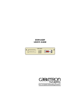
The ESX-1320 and ESX-1380 Ethernet Workgroup Switches, shown in
Figure 1-1, are standalone network switch devices. Except for the
difference in the network media supported (ESX-1320, RJ45 Twisted Pair
ports and ESX-1380, Multimode Fiber Optic ST ports), the two ESX
switches are identical in operation.
Figure 1-1 ESX-1320 and ESX-1380 Switches
NOTE
Throughout this manual the term ESX refers to both switches,
the ESX-1320 and the ESX-1380. If the information applies to
only one of the switches, then that switch is referred to by its
model name, ESX-1320 or ESX-1380.
1574-01
7X 8X 9X 10X 11X 12X1X 2X 3X 4X 5X 6X
ESX-1320
COM 2 COM 1
DISPLAY RESET
MULTI PORT ETHERNET SWITCH
WITH FDSE
™
AND LANVIEW
®
PWR
CPU
RECEIVE
TRANSMIT
PORT
1234 56789101112
BRIM-A100
STY
LNK
XMT
RCV
ESX-1380
COM 2 COM 1
DISPLAY RESET
MULTI PORT ETHERNET SWITCH
WITH FDSE
™
AND LANVIEW
®
PWR
CPU
RECEIVE
TRANSMIT
PORT
1234 56789101112
BRIM-A100
STY
LNK
XMT
RCV
PORT 12
TXRX
PORT 11
TXRX
PORT 10
TXRX
PORT 9
TXRX
PORT 8
TXRX
PORT 7
TXRX
PORT 6
TXRX
PORT 5
TXRX
PORT 4
TXRX
PORT 3
TXRX
PORT 2
TXRX
PORT 1
TXRX

Chapter 1:
Introduction
1-2 ESX-1320/ESX-1380 Installation Guide
1.1 USING THIS MANUAL
You should have a general working knowledge of Ethernet or IEEE 802.3
type data networks and their physical layer components, prior to installing
the ESX. The following summarizes the organization of this manual.
Chapter 1,
Introduction
, provides instructions for using this manual,
product features, document conventions, related documents, and how to
contact Cabletron Technical Support.
Chapter 2,
Controls and Indicators
,
discusses the controls and
indicators for the ESX.
Chapter 3,
Installation
,
provides instructions required to unpack the
ESX, perform pre-installation testing, install the ESX, and connect the
ESX to the network.
Chapter 4,
Troubleshooting
, provides detailed troubleshooting
procedures for the ESX.
Appendix A,
Specifications
, contains information on functionality and
operating specifications, connector pinouts, environmental requirements,
and physical properties.
Appendix B,
Ethernet Cabling Requirements
, contains information on
general networking guidelines.
1.2 FEATURES
i960 RISC Processor Controlled
The ESX complies to the PLUS Architecture with Dual Intel i960 RISC
processors and provides advanced management capabilities such as
SNMP, RMON, and DLM. The ESX provides the option of using
Cabletron Systems Distributed LAN Monitor (DLM) software to locally
poll and monitor any SNMP or IP device.

Features
ESX-1320/ESX-1380 Installation Guide 1-3
Connectivity
The ESX-1320 switch connects to the external Ethernet networks or
workstations through the 12 standard RJ45 connectors on its front panel.
The RJ45 connectors (interface ports) support Unshielded Twisted Pair
(UTP) and Shielded Twisted Pair (STP) cabling at lengths up to 100
meters. The ports are IEEE 802.3 10BASE-T compliant.
The ESX-1380 switch connects to the external Ethernet networks or
workstations through the 12 Fiber Optic ST connectors on its front panel.
The ports are Fiber Optic Inter-Repeater Link (FOIRL) compliant.
The ESX provides a port located on the front panel that supports one
Cabletron Systems Bridge/Router Interface Module (BRIM). BRIMs are
an optional feature for the ESX that provide flexible, integrated switching
functions to the workgroup and enterprise network hub. Refer to the
Release Notes
for a list of BRIMs currently supported by the ESX.
Memory
The ESX has 4 Megabytes (MB) of Shared Dynamic Random Access
Memory (SDRAM), 4 MB of Local Dynamic Random Access Memory
(LDRAM), and 2 MB of FLASH Electrically Erasable Programmable
Read Only Memory (FLASH EEPROM). A new firmware image can also
be loaded while the system is operating through a Runtime Download.
This option allows the loading of a new firmware image from a network
interface into FLASH memory while the ESX is operating with the “old”
image. In addition, the ESX motherboard provides the option of
upgrading memory capacity by using Single In-line Memory Modules
(SIMMs). Cabletron Systems currently offers an 8 MB upgrade for
LDRAM and SDRAM (Part Number 8MB-SCM-UGK-60). Note that the
SDRAM is used for packet processing; the LDRAM is used for statistical
information and RMON support.
Full Duplex Switched Ethernet (FDSE)
Each switched Ethernet port supports full wire-speed Ethernet
communications and can be configured to operate in FDSE mode. FDSE
allows each port to provide a dedicated 20 Mbps bandwidth for file server
or high-end workstation connections.

Chapter 1:
Introduction
1-4 ESX-1320/ESX-1380 Installation Guide
Management
The ESX can be managed using Local Management (LM) tools or remote
SNMP management stations. Out-of-band Local Management is provided
through RS232 COM ports on the front panel using a standard VT220 or
VT320 terminal or emulator. In-band remote management is possible
through any SNMP compliant Network Management System (NMS).
Traditional Switching
The ESX provides Traditional Switching or future S
ECURE
F
AST
Switching Virtual Network Services between all of the front panel
interfaces as well as the high-speed uplink BRIM interface. This allows
for future migration to Virtual Network technologies without requiring the
replacement of existing infrastructure purchases.
IEEE 802.3 Compatibility
The ESX provides IEEE 802.1d Spanning Tree Algorithm (STA) support
to enhance the overall reliability of the network and protect against “loop”
conditions. The ESX supports a wide variety of industry standard MIBs
including RFC 1213 (MIB II), RFC 1757 (RMON), and RFC 1493
(Bridge MIB). A full suite of Cabletron Systems Enterprise MIBs provide
a wide array of statistical information to enhance troubleshooting.
LANVIEW Diagnostic LEDs
The LANVIEW diagnostic and status monitoring LEDs serve as an
important troubleshooting aid by providing an easy way to observe the
status of individual ports and overall network operations. Chapter 4
provides details about the ESX LANVIEW LEDs.
LCD Display
The front panel LCD Display provides information on power-up
diagnostics, hardware and firmware revision levels, IP address, serial
number, and alarms. This allows non-technical personnel to provide
network technicians with basic information critical to the troubleshooting
process through simple push-button operation. Chapter 4 provides details
about the LCD Display.
1.3 DOCUMENT CONVENTIONS
The following conventions are used throughout this document:

Related Manuals
ESX-1320/ESX-1380 Installation Guide 1-5
1.4 RELATED MANUALS
The following manuals may help the user to control and manage the ESX
using SNMP network management systems.
Cabletron Systems
ESX-1320/ESX-1380 Local Management Guide
Cabletron Systems
SPECTRUM Element Manager
Cabletron Systems
SPECTRUM
and
SPECTRUM Portable
Management
Applications
(SPMA) manuals
Documentation for Third Party SNMP compliant Network Management
Packages
1.5 GETTING HELP
If you need additional support related to this device, or if you have any
questions, comments, or suggestions concerning this manual, contact
Cabletron Systems Technical Support:
NOTE
Note
symbol. Calls the reader’s attention to any item of
information that may be of special importance.
TIP
Tip
symbol. Conveys helpful hints concerning procedures or
actions.
!
CAUTION
Caution
symbol. Contains information essential to avoid
damage to the equipment.
Electrical Hazard Warning
symbol. Warns against an action
that could result in personal injury or death due to an electrical
hazard.
Phone (603) 332-9400
Monday – Friday; 8
A
.
M
. – 8
P
.
M
. Eastern Time
CompuServe GO CTRON from any ! prompt
Internet mail [email protected]

Chapter 1:
Introduction
1-6 ESX-1320/ESX-1380 Installation Guide
Before calling Cabletron Systems Technical Support, have the following
information ready:
• A description of the failure
• A description of any action(s) already taken to resolve the problem
(e.g., changing mode switches, rebooting the unit, etc.)
• A description of your network environment (layout, cable type, etc.)
• Network load and frame size at the time of trouble (if known)
• The serial and revision numbers of all Cabletron Systems products in
the network
• The device history (i.e., have you returned the device before, is this a
recurring problem, etc.)
• Any previous Return Material Authorization (RMA) numbers
FTP ctron.com (134.141.197.25)
Login
anonymous
Password
your email address
BBS (603) 335-3358
Modem setting 8N1: 8 data bits, 1 stop bit, No parity
For additional information about Cabletron Systems products, visit our
World Wide Web site: http://www.cabletron.com/

ESX-1320/ESX-1380 Installation Guide 2-1
CHAPTER 2
CONTROLS AND INDICATORS
This chapter provides descriptions of the controls and indicators for the
ESX-1320 and ESX-1380 Ethernet Workgroup Switches shown in
Figure 2-1.
Figure 2-1 ESX-1320 and ESX-1380 Switches
2.1 LANVIEW LEDs
The ESX-1320 and ESX-1380 incorporate the Cabletron Systems
LANVIEW status monitoring and diagnostics system. LANVIEW LEDs
(PWR, CPU, TRANSMIT, and RECEIVE) help diagnose problems, such
as power failures or a cable fault.
2.2 RESET BUTTON
The front panel of the ESX has a RESET button that allows you to
re-initialize the processor. Chapter 4 provides procedures for using the
RESET button.
1574-01
7X 8X 9X 10X 11X 12X1X 2X 3X 4X 5X 6X
ESX-1320
COM 2 COM 1
DISPLAY RESET
MULTI PORT ETHERNET SWITCH
WITH FDSE
™
AND LANVIEW
®
PWR
CPU
RECEIVE
TRANSMIT
PORT
1234 56789101112
BRIM-A100
STY
LNK
XMT
RCV
ESX-1380
COM 2 COM 1
DISPLAY RESET
MULTI PORT ETHERNET SWITCH
WITH FDSE
™
AND LANVIEW
®
PWR
CPU
RECEIVE
TRANSMIT
PORT
1234 56789101112
BRIM-A100
STY
LNK
XMT
RCV
PORT 12
TXRX
PORT 11
TXRX
PORT 10
TXRX
PORT 9
TXRX
PORT 8
TXRX
PORT 7
TXRX
PORT 6
TXRX
PORT 5
TXRX
PORT 4
TXRX
PORT 3
TXRX
PORT 2
TXRX
PORT 1
TXRX

Chapter 2: Controls and Indicators
2-2 ESX-1320/ESX-1380 Installation Guide
2.3 LCD DISPLAY
The ESX is equipped with an LCD display located on the front panel. The
LCD provides status information about the present as well as past
conditions of the ESX. You can view power up diagnostics, firmware
revisions, MAC addresses, IP addresses, and alarm messages. The LCD
displays the most current event, but can store up to 25 past events in
memory. Chapter 4 provides details about the LCD Display.
2.4 NETWORK MANAGEMENT CAPABILITIES
You can control and manage the ESX using any of the following SNMP
network management systems:
• Cabletron Systems Local Management
• Cabletron Systems SPECTRUM
• Cabletron Systems SPECTRUM Element Manager for Windows
• Cabletron Systems Remote SPECTRUM Portable Management
Applications
• Third Party SNMP compliant Network Management Packages
Network management capabilities provide the necessary management
tools for the ESX to operate at full capacity. Your ability to set up
parameters with network management ensures optimal performance of
the ESX.
Refer to the applicable network management package user’s manual for
more information.
2.5 SIMPLEX OR FULL DUPLEX MODE OPERATION
With FDSE, each switched port can be configured to operate in simplex or
full duplex mode. The default is simplex mode.
In simplex mode, a port can send and receive, but not both
simultaneously. Collision detection is turned on. In the full duplex mode,
the transmit and receive paths operate independently, collision detection
is turned off (eliminating the collision domain), and a separate CRC
generator and receive CRC checker are used on the port transmit and
receive lines for error detection.

Simplex or Full Duplex Mode Operation
ESX-1320/ESX-1380 Installation Guide 2-3
To set a port for full duplex operation using MIB Navigator, proceed as
follows:
1. Access Local Management as described in the ESX-1320/ESX-1380
Local Management Guide.
2. Select MIB Navigator via the Local Management Main Menu screen.
The
MIBNav -> prompt appears.
3. Enter the following commands (shown in bold type) at the
MIBNav -> prompt as shown below:
MIBNav -> ctron
MIBNav -> cd 4/3/3/2/1/1
MIBNav -> set 5[x] y
where x equals the port number (1 through 12)
where
y can equal either 2 for simplex mode or 3 for
full duplex mode. For example:
set 5[3] 3 would set
port 3 for full duplex operation.
For more information concerning MIB Navigator, refer to the
ESX-1320/ESX-1380 Local Management Guide.

Chapter 2: Controls and Indicators
2-4 ESX-1320/ESX-1380 Installation Guide

ESX-1320/ESX-1380 Installation Guide 3-1
CHAPTER 3
INSTALLATION
This chapter provides the instructions to install and connect the ESX to
the network. It includes the following procedures:
• Unpacking the ESX (Section 3.1)
• Removing the chassis cover (Section 3.2)
• Locating and setting the mode switches (Section 3.3)
• Using the NVRAM reset switch (Section 3.4)
• Adding/replacing Single In-line Memory Modules (SIMMs)
(Section 3.5)
• Identifying the BRIM connector location (Section 3.6)
• Installing the ESX on a shelf or into a standard rack (Section 3.7)
• Pre-network installation testing (Section 3.8)
• Connecting to a network (Section 3.9)
Only qualified personnel should perform installation
procedures.
NOTE
For information on how to install an optional BRIM, refer to your
specific BRIM documentation.

Chapter 3: Installation
3-2 ESX-1320/ESX-1380 Installation Guide
3.1 UNPACKING THE ESX
Unpack the ESX as follows:
1. Remove the shipping material covering the ESX.
2. Verify the contents of the packing carton. The carton, as shipped,
should contain the following items:
• ESX-13XX
• Firmware Images, 2
• Grounding strap
• RJ45 Adapter Kit
• Release Notes
• Rack Mounting Kit
• Accessory Kit
• ESX-1320/ESX-1380 Installation Guide
• ESX-1320/ESX-1380 Local Management Guide
3. If any of these items are missing, contact Cabletron Systems Technical
Support immediately. For help, refer to Section 1.5.
4. Carefully remove the ESX from the shipping box.
5. Visually inspect the ESX. If there are any signs of damage, contact
Cabletron Systems Technical Support immediately. For help, refer to
Section 1.5.
/