
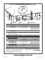
The Signature Series is NOT designed for amateur installation. Installation SHOULD be performed by an authorized technician.
Please read this manual carefully before installation and keep it for future reference.
The Signature Series is NOT designed for amateur installation. Installation SHOULD be performed by an authorized technician.
Please read this manual carefully before installation and keep it for future reference.
Owner & Installation
Manual
MGD*95SE*XA Gas Furnace
Signature Series

507277-03C Page 1 of 53mrcool.com
INSTALLATION INSTRUCTIONS
MGD*95SE*XA
Warm Air Gas Furnace
Save these instructions for future reference
(P) 507277-03C
*P507277-03C*
Manufactured By
MRCOOL,LLC
Hickory, KY 42051
This manual must be left with the homeowner for future reference.
WARNING
CAUTION
Table of Contents
Unit Dimensions 2
Parts Arrangement 3
Gas Furnace 4
4
Safety Information 4
6
6
9
12
Duct System 12
14
28
31
34
37
41
42
43
44
46
52

507277-03CPage 2 of 53 mrcool.com
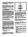
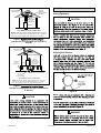
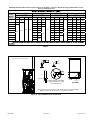
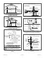
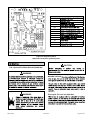
EXHAUST AIR
OUTLET
COMBUSTION
AIR INTAKE
2 1/16 (52)
GAS PIPING INLET
(Either Side)
ELECTRICAL INLET
(Either Side)
Return Air
Opening
WEIVEDIS
TOP VIEW
27 3/4
19
1/4
(489)
9
1/8 (232) Right
6 9/16 (167) Left
2 (51)
Either Side
3/4
(19)
B
Supply
Air
9/16
(14)
9/16
(14)
9/16
(14)
19
7/16
(494)
CONDENSATE
TRAP CONNECTION
5
(127)
6
1/2 (165)
Either Side
2 1/4
(57)
(Either Side)
1 (25)
Front Panel
(705)
AIR FLOW
33
(838)
C
3/4
(19)
3/4
(19)
FRONT VIEW
Supply
Air
9/16
(14)
9
(229)
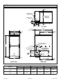
Unit Dimensions
Capacity
A B C
in. mm in. mm in. mm
045-3
070-4
17-1/2 446 16-3/8 416 16 406
090-4
110-5
21 533 19-7/8 504 19-1/2 495

507277-03C Page 3 of 53mrcool.com
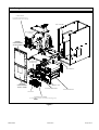
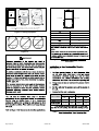
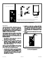
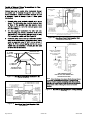
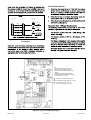
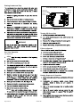
Figure 1.
CONTROLBOX
(Includesintegratedcontrol,
transformer and door switch)
BAG ASSEMBLY
BLOWERMOTOR
(hidden)
COMBUSTION
AIR INDUCER
BURNERBOX ASSEMBLY
(include
sensor, rolloutswitchesandignitor)
GAS VALVE
BLOWERDECK
HEAT EXCHANGER
COLDENDHEADERBOX
PRIMARY LIMIT
BLOWER
ACCESS PANEL
HEATING
ACCESS PANEL
COMPARTMENT
COMPARTMENT
Parts Arrangement

507277-03CPage 4 of 53 mrcool.com
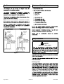
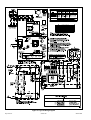
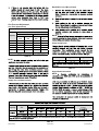
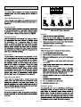
Gas Furnace
NOTE: In Direct Vent installations, combustion air is taken
Non-Direct Vent installations, combustion air is taken from
Figure 2.
Shipping and Packing List
1 - Wire tie
NOTE:
Safety Information
DANGER OF EXPLOSION!
DANGER
Building Codes

507277-03C Page 5 of 53mrcool.com
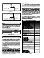
Locations and Clearances
NOTE:
NOTE:
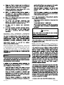
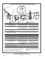
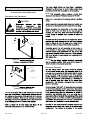
Installed in Combination with a Cooling Coil
HEAT or COOL
Quincy, MA 02269
Heating Unit Installed Parallell to Air Handler Unit
AIR HANDLER
GAS UNIT
Dampers
(open duringcooling
operationonly)
Dampers
(openduringheating
operationonly)
Figure 3.
NOTE:
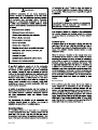
Use of Furnace as a Construction Heater
DO NOT USE THE UNIT FOR CONSTRUCTION HEAT
UNLESS ALL OF THE FOLLOWING CRITERIA ARE
MET:

507277-03CPage 6 of 53 mrcool.com
EQUIPMENT MAY EXPERIENCE PREMATURE
COMPONENT FAILURE AS A RESULT OF FAILURE TO
DISCLAIMS ALL LIABILITY IN CONNECTION WITH
NOTWITHSTANDING THE FOREGOING, INSTALLER
IS RESPONSIBLE FOR CONFIRMING THAT THE USE
OF CONSTRUCTION HEAT IS CONSISTENT WITH
THE POLICIES AND CODES OF ALL REGULATING
General
•
•
•
•
•
NOTE:
•
•
•
CAUTION
Combustion, Dilution & Ventilation Air
NOTE: In Non-Direct Vent Installations, combustion air is

507277-03C Page 7 of 53mrcool.com
•
•
•
•
•
•
•
•
•
•
•
•
•
WARNING
CAUTION
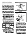
Air from Inside

507277-03CPage 8 of 53 mrcool.com
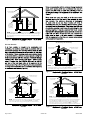
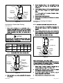
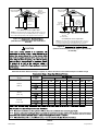
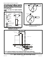
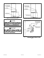
Figure 4.
Inside
OPENINGS
(To Adjacent
Space)
NOTE : Each opening shall have a free area of at least one square inch
per 1,000 Btu(645 mm
2
per .29 kW) per hour ofthetotal inputratingof
all equipmentin the enclosure,but not lessthan 100squareinches
(64516 mm
2
ROOFTERMINATED
EXHAUSTPIPE
SIDEWALL
TERMINATED
EXHAUSTPIPE
(ALTERNATE
LOCATION)
FURNACE
).
Air from Outside
(Inlet Air from Crawl Space and Outlet Air to Ventilated Attic)
NOTE: Theinlet and outlet air openings shall each have a free area
of at least one square inch per 4,000 Btu (645 mm
2
per 1.17 kW) per
hour of the total input rating of all equipment in the enclosure.
OUTLET
AIR
INLET
AIR
VENTILATION
LOUVERS
(Forunheated
crawl space)
FURNACE
ROOFTERMINATED
EXHAUSTPIPE
VENTILATIONLOUVERS
(Each end of attic)
SIDEWALL
TERMINATED
EXHAUSTPIPE
(ALTERNATE
LOCATION)
Figure 5.
Outside
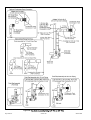
Figure 6.
Outside
(All Air Through Ventilated Attic)
NOTE: Theinlet and outlet air openings shall each have a free area of
at least one square inch per 4,000 Btu (645 mm
2
per 1.17 kW) per hour
of the total input rating of all equipment in the enclosure.
OUTLET
AIR
VENTILATION LOUVERS
(Each end of attic)
INLETAIR
(Ends12"above
bottom)
ROOFTERMINATED
EXHAUSTPIPE
SIDEWALL
TERMINATED
EXHAUSTPIPE
(ALTERNATE
LOCATION)
FURNACE
Figure 7.
Outside
OUTLET AIR
INLETAIR
NOTE: Each air duct opening shall have a free area of at least one
square inch per 2,000 Btu (645 mm
2
per .59 kW) per hour of the total
input rating of all equipment in the enclosure. If the equipment room
is located against an outside wall and the air openings communi-
cate directly with the outdoors, each opening shall have a free area
of at least 1 square inch per 4,000 Btu (645 mm
2
per 1.17 kW)per
hour of the total input rating of all other equipment in the enclosure.
ROOFTERMINATED
EXHAUSTPIPE
SIDEWALL
TERMINATED
EXHAUSTPIPE
(ALTERNATE
LOCATION)
FURNACE

507277-03C Page 9 of 53mrcool.com
Figure 8.
(Inlet Air from Ventilated Attic and Outlet Air to
Outside)
NOTE-The inlet and outlet air openings shall each have a free area
of at least one square inch per 4,000 Btu (645mm
2
per 1.17kW) per
hour of the total input rating of all equipment in the enclosure.
Ventilation Louvers
Inlet Air
(Minimum
12 in.(305mm) Above
attic floor)
Roof Terminated
Exhaust Pipe
Furnace
*Intake Debris
Screen
(Provided)
* See Maximum Vent Lengths table
Figure 9.
(Inlet Air from Ventilated Crawl Space and Outlet Air
to Outside)
NOTE-The inlet and outlet air openings shall each have a free area
of at least one square inch per 4,000 Btu (645mm
2
per 1.17kW) per
hour of the total input rating of all equipment in the enclosure.
Roof Terminated
Exhaust Pipe
Furnace
Ventilation
Louvers
(Crawl space)
*Intake Debris Screen Provided)
Inlet Air
(Minimum
12 in.(305mm)
Above crawl
space floor)
Coupling or
3 in. to 2 in.
Transition
(Field Provided)
* See Maximum Vent Lengths table
CAUTION
Installation
Setting Equipment
CAUTION
Shipping Bolt Removal
Figure 10.
NOTE:
WARNING

507277-03CPage 10 of 53 mrcool.com
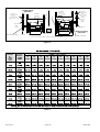
Figure 11. Setting Equipment
FRONTVIEW SIDEVIEW
AIR FLOW
AIR FLOW
1/2"
max.
AIR FLOW
SIDEVIEW
Unit must be level side−to−side. Unit may be positioned
from level to 1/2"towardthe frontto aid in draining.
Figure 12.
WARNING
Top
Bottom
Left Side Right Side
Top 0
*Front 0
Back 0
Sides 0†
Vent 0
Floor NC‡
*Frontclearancein alcove installationmustbe 24 in. (610mm).
Maintain a minimumof 24 in. (610mm) for frontserviceaccess.
†Allow proper clearances to accommodate condensate trap.
‡The furnace may be installed on a combustible wood
oorifan optional
additive base is install
Figure 13.
Clearances
0
*Front 0
Back 0
Sides 0†
0
NC‡
See Figure 14
Table 1.
Cabinet Width
Front to Rear Side to Side
in. mm in. mm
19-3/4 502 16-5/8 422
19-3/4 502 20-1/8 511
NOTE

507277-03C Page 11 of 53mrcool.com
Figure 14.
SUPPLY AIR
PLENUM
PROPERLY
SIZED FLOOR
OPENING
FURNACE
NON-COMBUSTIBLE
FLOORING
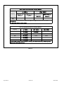
Installation on Combustible Flooring
See Figure 15
CAUTION
Table 2.
Cabinet
Width
Catalog
Number
Front to Rear Side to Side
in. mm in. mm
11M60 22 559 18-3/4 476
(21”)
11M61 22 559 22-3/4 578
Figure 15.
FURNACE
SUPPLY AIR
PLENUM
COMBUSTIBLE
FLOORING BASE
PROPERLY
SIZED FLOOR
OPENING
FLOORING
COMBUSTIBLE
NOTE:
Installation on Cooling Coil Cabinet
See Figure 16
NOTE:
Figure 16.
COOLING COIL
PLENUM
PROPERLY
SIZED FLOOR
OPENING
FURNACE

507277-03CPage 12 of 53 mrcool.com
Figure 17.
SECURE FROM
OUTSIDECABINET
PLENUM
(Field Provided)
SEALINGSTRIP
(Field Provided)
Side View
CABINET
SIDE PANEL
Figure 18.
SECUREFROM
INSIDECABINET
PLENUM
(Field Provided)
SEALINGSTRIP
(Field Provided)
Side View
CABINET
SIDE PANEL
Filters
Table 3.
Furnace Cabinet Width
17-1/2”
21”
Duct System
NOTE:
Supply Air Plenum
Return Air Plenum
NOTE:
Table 4.
D1785
F891
D2466
F441
F438
D2241
F442
F628
D1527
D2468
D2661
D2665
PRIMER & SOLVENT CEMENT
ASTM
SPECIFICATION
F656
D2564
F493
D2235
D2564, D2235,
F493
Cement
D3138
CANADA PIPE & FITTING & SOLVENT
CEMENT
MARKING
ULCS636
POLYPROPYLENE VENTING SYSTEM
ULC-S636
ULC-S636
TM
ULC-S636

507277-03C Page 13 of 53mrcool.com
CAUTION
IMPORTANT
Canadian Applications Only
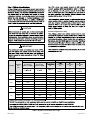
Table 5. Outdoor Termination Kits Usage
Capacity
Vent Pipe
Dia.
(in.)
Standard Concentric
Outdoor Exhaust
Accelerator
(Dia. x Length)
Outdoor Exhaust
Accelerator
(Dia. x Length)
Kit
Concentric
Kit
Concentric
Kit
Concentric
Kit
51W11**
71M80
or
†44W92††
69M29
or
†44W92††
60L46
or
44W93†
045
2 YES YES YES
2-1/2 YES YES YES
3 YES YES YES
070
2 YES YES YES
2-1/2 YES YES YES
3 YES YES YES
090
2 YES YES YES YES
2-1/2 YES YES YES YES
3 YES YES YES YES
110
2 YES YES YES YES
2-1/2 YES YES YES YES
3 YES YES YES YES

507277-03CPage 14 of 53 mrcool.com
Joint Cementing Procedure
NOTE:
DANGER OF EXPLOSION!
DANGER
NOTE:
NOTE:
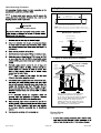
Venting Practices
Figure 19. Piping Suspension Guidelines
* SeeTable4 for allowable pipe.
NOTE: Isolate piping at the point where it exits the outside wall or
roof in order to prevent transmission of vibration to the structure.
SCHEDULE 40
PVC − 5’
all other pipe* − 3’
Wall
edistuoedisni
24"maximum
3/4"minimum
Wall Thickness Guidelines
insulation
(if required)
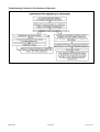
Figure 20.
CHIMNEY
OR GAS
VENT
(Checksizing
for remaining
appliance)
FURNACE
(Removed from
from common
vent system)
WATER
HEATER
OPENINGS
(To Adjacent
Room)
REPLACING FURNACE THAT
WAS PART OF A COMMON
VENT SYSTEM
If this gas furnace replaces a furnace which was
commonly vented with another gas appliance,
the size of the existing vent pipe for that gas appliance
must be checked. Without the heat of the original
furnace flue products, the existing vent pipe is
probably oversized for the single water heater or
other appliance. The vent should be checked for
proper draw with the remaining appliance.
Exhaust Piping
See Figure 22

507277-03C Page 15 of 53mrcool.com
CAUTION
CAUTION
Vent Piping Guidelines
NOTE: In non-Direct Vent installations, combustion air is
In Direct Vent installations, combustion air is taken from
Table 6. Minimum Vent Pipe Length
Capacity Min. Vent Length*
045, 070, 090, 110
IMPORTANT
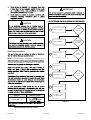
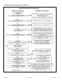
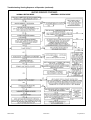
Figure 21.
045, 070,
090, 110
Standard or
Concentric?
See Table 5
Intake or
Exhaust?
2”, 2-1/2”
or 3”
Furnace capacity?
1
Which termination?
2
Which needs most
elbows?
3
How many?
4
Desired pipe size?
5
What is the altitude?
6
Use Table 7 to find
max pipe length.
7

507277-03CPage 16 of 53 mrcool.com
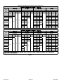
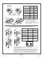
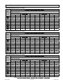
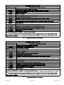
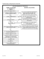
Maximum Allowable Intake or Exhaust Vent Length in Feet
Number
of 90
Elbows
Used
Capacity Capacity Capacity Capacity
045 070 090 110 045 070 090 110 045 070 090 110 045 070 090 110
1 20 15
n/a n/a
61 46 24
n/a
100 80 43
n/a
127 127 108 108
2 15 10 56 41 19 95 75 38 122 122 103 103
3 10
n/a
51 36 14 90 70 33 117 117 98 98
4
n/a
46 31
n/a
85 65 28 112 112 93 93
5 41 26 80 60 23 107 107 88 88
6 36 21 75 55 18 102 102 83 83
7 31 16 70 50 13 97 97 78 78
8 26 11 65 45
n/a
92 92 73 73
9 21
n/a
60 40 87 87 68 68
10 16 55 35 82 82 63 63
Number
of 90
Elbows
Used
Capacity Capacity Capacity Capacity
045 070 090 110 045 070 090 110 045 070 090 110 045 070 090 110
1 15 10
n/a n/a
53 38 22
n/a
90 70 39
n/a
111 111 104 104
2 10
n/a
48 33 17 85 65 34 106 106 99 99
3
n/a
43 28 12 80 60 29 101 101 94 94
4 38 23
n/a
75 55 24 96 96 89 89
5 33 18 70 50 19 91 91 84 84
6 28 13 65 45 14 86 86 79 79
7 23
n/a
60 40
n/a
81 81 74 74
8 18 55 35 76 76 69 69
9 13 50 30 71 71 64 64
10 n/a 45 25 66 66 59 59
Table 7.

507277-03C Page 17 of 53mrcool.com
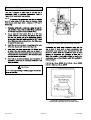
Figure 22. Typical Exhaust Pipe Connections
TRANSITION
2”
2”
2”
3”
Pipe sizedeterminedin Table7.
2”
2”
or
DO NOT transition from smaller
to larger pipe size in horizontal
runs of exhaust pipe.
TOP VIEW
EXHAUST
INTAKE
* When transitioning up in pipe size, use the shortest length of 2” PVC pipe possible.
NOTE: Exhaust pipe and intake pipe must be the same diameter.
*2”
Maximum Allowable Exhaust Vent Lengths with Furnace Installed in a Closet or Basement Using Ventilated Attic or Crawl
Space for Intake Air in Feet
Number
of 90
Elbows
Used
Capacity Capacity Capacity Capacity
045 070 090 110 045 070 090 110 045 070 090 110 045 070 090 110
1 15 10
n/a n/a
61 46 24
n/a
100 80 43
n/a
127 127 108 108
2 10
n/a
56 41 19 95 75 38 122 122 103 103
3
n/a
51 36 14 90 70 33 117 117 98 98
4 46 31
n/a
85 65 28 112 112 93 93
5 41 26 80 60 23 107 107 88 88
6 36 21 75 55 18 102 102 83 83
7 31 16 70 50 13 97 97 78 78
8 26 11 65 45
n/a
92 92 73 73
9 21
n/a
60 40 87 87 68 68
10 16 55 35 82 82 63 63
NOTE
Table 8.

507277-03CPage 18 of 53 mrcool.com
Figure 23. Typical Intake Pipe Connections (Direct Vent Applications)
2”
2”
TRANSITION
2”
3”
TRANSITION
3”
Pipe sizedeterminedin Table7.
2”
2”
or
TOP VIEW
EXHAUST
INTAKE
* When transitioning up in pipe size, use the shortest length of 2” PVC pipe possible.
NOTE: Intake pipe and exhaust pipe must be the same diameter.
*2”
*2”
*2”
Intake Piping
AIR
INTAKE
SCREEN
(Provided)
NOTE: Air intake screen and elbow may be rotated, so that
screen may be positioned to face forward or to either side.
Figure 24. Typical Air Intake Pipe Connections

507277-03C Page 19 of 53mrcool.com
Figure 25.
(Inlet Air from Ventilated Attic and Outlet Air to
Outside)
NOTE-The inlet and outlet air openings shall each have a free area
of at least one square inch per 4,000 Btu (645mm
2
per 1.17kW) per
hour of the total input rating of all equipment in the enclosure.
Ventilation Louvers
Inlet Air
(Minimum
12 in.(305mm) Above
attic floor)
Roof Terminated
Exhaust Pipe
Furnace
*Intake Debris
Screen
(Provided)
* See Maximum Vent Lengths table
CAUTION
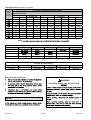
Table 9.
Maximum Allowable Exhaust Vent Pipe Length (in ft.) without Insulation in Unconditioned Space for Winter Design
Winter Design Temperatures
1
ºF (ºC)
Vent Pipe
Diameter
045 070 090 110
32 to 21
(0 to -6)
PVC
2
PP PVC
2
PP PVC
2
PP PVC
2
PP
18 16 31 28 50 48 30 30
13 N/A 24 N/A 42 N/A 56 N/A
9 9 18 18 35 35 47 47
20 to 1
(-7 to -17)
9 8 18 16 32 29 30 30
5 N/A 13 N/A 24 N/A 34 N/A
N/A N/A 8 8 19 19 26 26
0 to -20
(-18 to -29)
5 3 12 10 22 19 30 27
N/A N/A 7 N/A 15 N/A 22 N/A
N/A N/A N/A N/A 10 10 16 16
1
2
NOTE
NOTE
NOTE
Figure 26.
(Inlet Air from Ventilated Crawl Space and Outlet Air
to Outside)
NOTE-The inlet and outlet air openings shall each have a free area
of at least one square inch per 4,000 Btu (645mm
2
per 1.17kW) pe
r
hour of the total input rating of all equipment in the enclosure.
Roof Terminated
Exhaust Pipe
Furnace
Ventilation
Louvers
(Crawl space)
*Intake Debris Screen Provided)
Inlet Air
(Minimum
12 in.(305mm)
Above crawl
space floor)
Coupling or
3 in. to 2 in.
Transition
(Field Provided)
* See Maximum Vent Lengths table
Page is loading ...
Page is loading ...
Page is loading ...
Page is loading ...
Page is loading ...
Page is loading ...
Page is loading ...
Page is loading ...
Page is loading ...
Page is loading ...
Page is loading ...
Page is loading ...
Page is loading ...
Page is loading ...
Page is loading ...
Page is loading ...
Page is loading ...
Page is loading ...
Page is loading ...
Page is loading ...
Page is loading ...
Page is loading ...
Page is loading ...
Page is loading ...
Page is loading ...
Page is loading ...
Page is loading ...
Page is loading ...
Page is loading ...
Page is loading ...
Page is loading ...
Page is loading ...
Page is loading ...
Page is loading ...
Page is loading ...
-
 1
1
-
 2
2
-
 3
3
-
 4
4
-
 5
5
-
 6
6
-
 7
7
-
 8
8
-
 9
9
-
 10
10
-
 11
11
-
 12
12
-
 13
13
-
 14
14
-
 15
15
-
 16
16
-
 17
17
-
 18
18
-
 19
19
-
 20
20
-
 21
21
-
 22
22
-
 23
23
-
 24
24
-
 25
25
-
 26
26
-
 27
27
-
 28
28
-
 29
29
-
 30
30
-
 31
31
-
 32
32
-
 33
33
-
 34
34
-
 35
35
-
 36
36
-
 37
37
-
 38
38
-
 39
39
-
 40
40
-
 41
41
-
 42
42
-
 43
43
-
 44
44
-
 45
45
-
 46
46
-
 47
47
-
 48
48
-
 49
49
-
 50
50
-
 51
51
-
 52
52
-
 53
53
-
 54
54
-
 55
55


MRCOOL MGD95SE110C5XA Installation guide
- Type
- Installation guide
- This manual is also suitable for
Ask a question and I''ll find the answer in the document
Finding information in a document is now easier with AI
Related papers
-
MRCOOL Signature Downflow 96% AFUE Furnace Install Manual
-
-
MRCOOL MGM95SE135D5XA Installation guide
-
-
MRCOOL MAC1618H24GM845 User manual
-
-
-
-
-
MRCOOL O-ES-18-HP-230E User manual
Other documents
-
 T & S Brass & Bronze Works EW-8904 Datasheet
-
Lennox EL297DFV User manual
-
Gibraltar Building Products CHADS-1/8 Installation guide
-
Lennox ML196DFE Series Units Installation guide
-
-
-
-
-
 THERMALUX NERC11DV–LP Operating instructions
-
 Cozy WOW404 and User manual


