Page is loading ...

INSTALLATION MANUAL
INSTALLATION MANUALINSTALLATION MANUAL
INSTALLATION MANUAL
100
100 100
100 Alutec
AlutecAlutec
Alutec®
® ®
® 70
70 70
70 VOLTA OVEN
VOLTA OVENVOLTA OVEN
VOLTA OVEN
CODE: 55028
CODE: 55028CODE: 55028
CODE: 55028

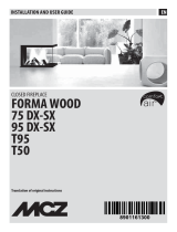
ASSEMBLY STEPS
PARTS LIST
1/2/3/4/5/6/7 - OVEN FIRE PLANE
8/9/10/11/12/13/14 - OVEN VAULT
15/16/17 - OVEN ARC
18 - STEEL DOOR

DIMENSIONS
TECHNICAL DATA
MINIMUM ROOM VOLUME : 132 m
3
OPTIMUM WOOD CONSUMPTION : 11 Kg/h
TOTAL WEIGHT : 451 Kg
EXTERNAL AIR INLET : 350 cm
2
FLUE PIPE
SECTION: 25x 25 Height: 5.5 - 10 m
SECTION: ø 25 Height: 5.5 - 10 m
SECTION: 30x 30 Height: 3.5 - 5 m
SECTION: ø 30 Height: 3.5 - 5 m

ACCESSORY
40160029: AC RAC.OVEN C/V.VOLTA OVEN100/120
NOTE:
NOT SUPPLIED AS STANDARD BUT REQUIRED FOR
CORRECT INSTALLATION OF THE OVEN.
1.
INSTALLATION INSTRUCTIONS
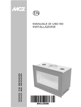
The oven is a special wood-fired heat generator designed for cooking
food. In a traditional dome oven (also called a direct fire oven) heat is
transferred via direct radiation of the flame inside the cooking
chamber, conduction of heat from the lower fire plane and reflection of
heat from the inner surface for the upper vault (diagram fig. 1/1).
Food is cooked in the same, half spherical, chamber;
The hole that the smoke exits from is positioned above a curved part (ARC). The arc is located in front of the
stoke-hole.
When the wood is burnt heat runs along the inner surfaces of the vault, exits from the stoke-hole and enters the
joint positioned above the arc. This system provides excellent and uniform heating of the structure, making heat
available for cooking even after the fire has been put out.
2. GENERAL SAFETY RULES
Rules for general safety and correct operation, valid for all models, are as follows:
Assemble the oven on a finished floor;
Carry out preliminary technical checks of the minimal room volume, the external air inlet, the smoke
connection, the flue pipe and the chimney to identify any faults;
Always use the oven assembly diagram, checking thoroughly that all parts are positioned correctly;
If the floor next to the stoke-hole is made of combustible material a protective device must be made using
fireproof material. This protection must protrude from the stoke-hole of the oven by the height value of the
fire plane plus 30 cm and not be less than 60 cm. The protection must protrude from the other sides by the
height value of the fire plane plus 20 cm and not be less than 40cm.
You are advised to always leave a gap of at least 5 centimetres between the oven and walls to insulate the walls
if they are made from flammable material;
Avoid electrical systems or similar devices outside wall cavities located close to the combustion chamber;
Fig.1/
1

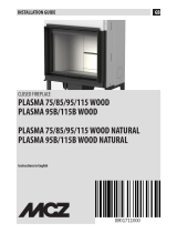
3. INSTALLATION INSTRUCTIONS
Before installing the oven check the area in which you
wish to position it (figure 1/2), taking into account the
minimal room volume of 132 m
3
and the total overall
dimensions of the oven itself (see page 3).
Using the instructions and heights shown, identify where
to:
Make the hole for the external combustion air inlet
(figure 1/3 point A);
Make the hole for the smoke connection passage
(figure 1/3 point B).
Always position the external and internal combustion air
inlet close to the ceiling and equal to the dimensions
shown in the technical data (see page 3).
Build a safe, horizontal support surface if one is not
already present (figure 1/4).
The dimensions of the base must correspond to the
external measurements of the oven with added thickness
for insulation. (see Fig.1/10).
Fig.1/2
Fig.1/3
Fig.1/4

Once the support surface is in place, proceed with the assembly of the oven and insulation.
Figure 1/5 shows the structure of the Volta 100 oven:
1/2/3/4/5/6/7. Oven fire plane
8/9/10/11/12/14/. Oven vault
15/16/17. Front oven arc
18. Oven door
Spread a suitable layer of insulating material, for example
ceramic fibre or similar materials, over the surface of the base
(MINIMUM OF 3-5 cm). This material must be able to
withstand a minimum of 500 °C (figure 1/6).
Position the fire plane of the oven above the layer of insulant
(figure 1/7), checking that the parts meet correctly.
DO NOT grout the parts or use any other type of sealant (the
spaces in between the parts should fill with ash to prevent
excessive expansion). Check that the parts are stable on the layer
of insulant to prevent cracking. If necessary, push the parts until
they are positioned stably.
Fig.1/5
Fig.1/6
Fig.1/7

Assemble the parts of the vault and arc (figure 1/8) - do not lock them with mortal or sealants. Next, position the
smoke damper (supplied separately as an accessory) and finally attach the smoke connection. Insulate the smoke
connection with material resistant to a minimum of 500 °C and seek to position it at an angle no greater than 45°
(figure 1/9).
Remember to check that the dimensions of
the flue pipe match those shown in the
technical data (see page 3).
Cover the entire vault of the oven, including
the arc, with at least 5 cm of suitable
insulating material.
Finish the insulation by placing at least 10cm
of thick grain expanded clay (8/10 mm) on
the sides and rear of the oven and 20 cm on
the vault (figure 8/17).
This will provide excellent insulation to
ensure that the oven rises by the correct
temperature when heating up and cools down
slowly to provide an advantage when
cooking.
Moreover, this means that you do not need to
grout the inside of the oven with mortar and/
or refractory cements.
Fig.1/8
Fig.1/9
Fig.1/10

4. INSTRUCTIONS FOR CORRECT USE OF THE PRODUCT
Before using the oven as you normally would, it is advisable to briefly light the oven a few times to eliminate
any residual moisture and settle the parts. This is more pertinent for ovens positioned in external
environments where there is greater moisture present.
Do not use volatile flammable substances to light the fire, such as alcohol or similar chemical products.
Light the fire slowly with fine, dry wood until the refractory material takes on a light colour. This means that the
oven has reached the optimum temperature for cooking all types of food.
You are advised to use non-resinous, chopped, dried wood (20% humidity).
In some cases, when the fire is lit for the first time dense smoke will form inside the oven chamber. This is due
to the presence of moisture in the parts and the low temperature of the flue system.
In all cases, the inside of
the oven should never show a dark colour (deposits or black colouring). This indicates that the oven is cold
and therefore not suitable for any type of cooking.
Small cracks appearing following thermal expansion or due to construction factors (MICRO and MACRO
cracks) are distinctive characteristics of the refractory product and do not comprise the stability, durability or
functionality of the oven.
Many dishes can be cooked in the oven. There are two types of cooking system:
Heat convection cooking (indirect radiation): food is cooked after bringing the oven to the correct temperature
(white vault) and/ or residues have been cleaned from the compartment. No internal fire. Cooking suitable for
bread, biscuits, cakes and other items cooked slowly and gradually.
Flame cooking (direct radiation): food is cooked with the fire inside the oven. Cooking suitable for pizzas,
roasting, grilling meat and fish and many other foods.
5. IMPORTANT NOTE ABOUT VOLTA OVENS.
NEVER PLACE THE STEEL DOOR IN FRONT OF THE OVEN WHEN
THERE IS A FLAME INSIDE THE OVEN.
ONLY POSITION THE DOOR IN FRONT WHEN THERE IS NO FLAME
PRESENT.
FAILURE TO OBSERVE THIS RULE MAY CAUSE SERIOUS DAMAGE TO THE STRUCTURE OF
THE OVEN.
/