MCZ FORMA WOOD 75 DX-SX Use And Installation Manual
- Category
- Fireplaces
- Type
- Use And Installation Manual
This manual is also suitable for

8901161300
USE AND
INSTALLATION
MANUAL
EN

FORMA WOOD CLOSED FIREPLACE
Contents
USE AND MAINTENANCE MANUAL
page
2
Contents Technical dept. - All rights reserved by MCZ Group S.p.A. - Reproduction prohibited
INTRODUCTION....................................................................................................................................4
1. WARNINGS AND GUARANTEE TERMS...............................................................................................5
1.1. SAFETY WARNINGS ........................................................................................................................5
1.2. OPERATIONAL WARNINGS ..............................................................................................................5
1.3. GUARANTEE TERMS........................................................................................................................6
1.3.1. Guarantee limits.......................................................................................................................6
1.3.2. Exclusions................................................................................................................................6
1.4. IMPORTANT INFORMATION FOR CORRECT DISPOSAL OF THE PRODUCT IN ACCORDANCE WITH EC
DIRECTIVE 2002/96/EC .............................................................................................................................6
2. INSTALLATION IN COMPLIANCE WITH UNI 10683..........................................................................7
2.1. THE OPERATING ENVIRONMENT .....................................................................................................7
2.2. PRECAUTIONS................................................................................................................................7
2.3. CONNECTING THE EXTERNAL AIR INLET............................................................................................8
2.4. CONNECTING THE FLUE PIPE..........................................................................................................9
2.5. FLUE PIPE......................................................................................................................................9
2.5.1. Flue pipe examples.................................................................................................................10
2.6. CHIMNEY .....................................................................................................................................11
3. DIMENSIONS AND TECHNICAL SPECIFICATIONS..........................................................................12
3.1. Dimensions of the Forma Wood 75 rh-lh (fig. shows lh version)........................................................12
3.2. Dimensions of the Forma Wood 95 rh-lh (fig. shows lh version)........................................................13
3.3. Dimensions of the Forma Wood T95...............................................................................................14
3.4. Technical specifications .................................................................................................................15
4. INSTALLATION AND ASSEMBLY......................................................................................................16
4.1. PREPARATION AND UNPACKING....................................................................................................16
4.2. OPERATING MODE SELECTION......................................................................................................17
4.2.1. Natural convection (COMFORT AIR NV)....................................................................................17
4.2.2. Forced convection (COMFORT AIR FV) .....................................................................................17
4.3. COUNTERWEIGHT UNLOCKING .....................................................................................................17
4.4. POSITIONING...............................................................................................................................18
4.5. ADJUSTING THE HEIGHT AND LEVEL .............................................................................................19
4.6. EXTERNAL AND INTERNAL AIR INLETS ..........................................................................................20
4.6.1. Combustion air inlet................................................................................................................20
4.6.2. Air inlet for natural ventilation .................................................................................................20
4.6.3. Air inlet for forced ventilation ..................................................................................................20
4.6.3.1. Ducts for the COMFORT AIR kit.........................................................................................20
4.7. FLUE PIPE CONNECTION...............................................................................................................21
4.8. ASSEMBLING THE CLADDING AND REVERSE HOOD ........................................................................21
4.9. CLOSED FIREPLACE INSULATION ..................................................................................................22
4.10. WOOD BEAM INSULATION .........................................................................................................22
4.10.1.
Hood ventilation outlets.
......................................................................................................22
5. OPERATION.....................................................................................................................................23
5.1. WARNINGS PRIOR TO START-UP...................................................................................................23
5.2. OPERATING TEST.........................................................................................................................23
5.2.1. Stages for the first test start-up...............................................................................................24
5.3. CHOICE OF FUEL ..........................................................................................................................24
5.4. FIRST START-UP ..........................................................................................................................25
5.5. FUEL LOADING.............................................................................................................................26
5.6. COMBUSTION CONTROL ...............................................................................................................27
5.7. QUICK RESPONSE.........................................................................................................................27
6. MAINTENANCE AND CLEANING ......................................................................................................28
6.1. CLEANING UNDER THE USER'S RESPONSIBILITY ............................................................................28

FORMA WOOD CLOSED FIREPLACE
Contents
USE AND MAINTENANCE MANUAL
page
3
Contents Technical dept. - All rights reserved by MCZ Group S.p.A. - Reproduction prohibited
6.1.1.
Cleaning the glazing ...............................................................................................................28
6.1.2. Ash removal...........................................................................................................................28
6.1.3. Cleaning refractory walls (ALUTEC
®
)........................................................................................28
6.2. CLEANING UNDER THE RESPONSIBILITY OF A SPECIALISED TECHNICIAN .......................................29
6.2.1. Cleaning the flue pipe .............................................................................................................29

FORMA WOOD CLOSED FIREPLACE Chapter 1
USE AND MAINTENANCE MANUAL
page 4
Introduction Technical dept. - All rights reserved by MCZ Group S.p.A. - Reproduction prohibited
INTRODUCTION
Dear customer,
Thank you for choosing MCZ products and, in
particular, a closed fireplace from the Forma line.
This appliance has been produced through
painstaking design and thorough testing and we are
confident that, when using the appliance, you will
value the high quality that it offers. Our aim is to
combine technology with simple use and, first and
foremost, safety.
For optimal operation of the closed fireplace
and to benefit fully from the heat and sense of
well-being distributed throughout your home,
we advise you to read this manual carefully
before starting the appliance up for the first
time. In the event of faults or if in doubt please
contact your retailer who will provide all the
necessary assistance.
Please remember that this closed fireplace MUST
NOT be used by children. Children must always be
kept at a safe distance!
Document revisions
In order to improve the product and to update this
document, the Manufacturer reserves the right to
make any changes without notice.
All reproduction (including partial) of this manual
without the Manufacturer's authorisation is strictly
prohibited.
Care of the manual
Take care of this manual and keep it in a place
where it can be easily and quickly accessed.
Should you misplace or destroy the manual, or
should it come to be in poor condition, ask your
retailer or the Manufacturer for another copy,
specifying the product identification data.
How to consult the manual
Any vital topics or those requiring special
attention are printed in “bold text”.
“Italic text”
is used for any additional
explanations.
NOTE: the “NOTE” provides the reader with
additional information about the topic.
These symbols indicate specific
messages found in this manual
CAUTION!
This warning symbol indicates that you
should read carefully and understand the
message it refers to. Failure to observe
the instructions given may seriously
damage the closed fireplace and also
endanger the person using it.
INFORMATION:
This symbol is used to highlight the
information deemed important for the
correct functioning of the closed fireplace.
Failure to observe the instructions
provided will jeopardise the use of the
appliance and cause it to function
unsatisfactorily

FORMA WOOD CLOSED FIREPLACE Chapter 1
USE AND MAINTENANCE MANUAL
page 5
Warnings and guarantee terms Technical dept. - All rights reserved by MCZ Group S.p.A. - Reproduction prohibited
1. WARNINGS AND GUARANTEE
TERMS
1.1. SAFETY WARNINGS
Installation, electrical connection,
functional check and maintenance of this
appliance must only be performed by
qualified or authorised personnel.
Install the closed fireplace in compliance
with the applicable regulations in force in
the place, region or country.
This appliance must not be used by anyone
(including children) with limited physical,
sensory or mental skills or with little
experience and knowledge, unless they are
supervised or have been instructed to use
the device by the person in charge of its
safety.
Only use the fuel recommended by MCZ.
The appliance must not be used as an
incinerator. The use of liquid fuel is strictly
forbidden.
The instructions provided in this manual must
always be observed to ensure the correct use of
this closed fireplace and of any appliances
connected to it as well as to avoid any accidents.
The user (or anybody preparing to operate the
closed fireplace) must read and fully understand
the contents of this instruction manual before
beginning any operation.
The closed fireplace must only be used for its
intended purpose. Any other use is considered
incorrect and therefore dangerous.
Assess the static conditions of the surface on
which the weight of the closed fireplace will bear
and provide suitable insulation if it is made of
flammable material (e.g. wood, fitted carpet,
plastic).
Avoid installing the appliance in rooms containing
type B gas appliances or hoods with or without
an extractor fan, heat pumps, or collective
ventilation ducts.
Avoid having several operational flue ducts in the
room or in the proximity of a stair well and make
sure that there are no appliances in adjacent
communicating rooms, the concurrent use of
which causes a vacuum in one of the two rooms.
The user is fully liable for any incorrect use of the
product. MCZ bears no civil or criminal liability for
incorrect use.
Tampering of any nature or replacement of spare
parts with non-original parts may endanger the
operator. MCZ bears no civil or criminal liability
for tampering or use of non-original parts.
Parts of the surface of the closed fireplace can
get very hot (door, handle, glass). Therefore,
avoid touching these parts without wearing
suitable protective clothing or using appropriate
measures, such as heat protective gloves or
"hands cool" type systems.
Carefully explain this danger to elderly and
disabled people and, in particular, to all children,
keeping them away from the closed fireplace
while it is in use.
Incorrect installation or poor maintenance (not
conforming to the instructions provided in this
manual) may cause personal injury, harm to
animals or damage to property. MCZ bears no
civil or criminal liability for incorrect installation or
poor maintenance.
1.2. OPERATIONAL WARNINGS
Turn off the closed fireplace in the event of a
failure or malfunctioning.
Keep flammable material at least 150 cm away
from the glass of the fireplace.
If there is poor draught in the flue pipe (due to
bad weather, poor installation conditions) light
the flame strongly, keeping the door slightly
open. When the door is closed always keep the
damper completely open. Use dry wood in small
pieces. If you continue to experience problems
with the combustion call a qualified technician.
Install the closed fireplace in rooms which are
suitably protected against fire hazards and
equipped with all utilities, including power
supplies (air, water and electricity) and smoke
outlets.
Do not light the fire with flammable substances.
INFORMATION:
In case of any problems please contact your
retailer or MCZ's qualified, authorised personnel.
If repairs are necessary, request original spare
parts.
Check and clean the smoke outlet pipe regularly
in accordance with the provisions of the
applicable regulations in the country of
installation
Keep this instruction manual in a safe place as it
should accompany the closed fireplace along its
entire life cycle. If the closed fireplace is sold or
transferred to another user always ensure that
the manual accompanies the product.
If this manual is destroyed request a copy from
your authorised retailer or from MCZ.

FORMA WOOD CLOSED FIREPLACE Chapter 1
USE AND MAINTENANCE MANUAL
page 6
Warnings and guarantee terms Technical dept. - All rights reserved by MCZ Group S.p.A. - Reproduction prohibited
1.3. GUARANTEE TERMS
MCZ guarantees the product, with the exception of
parts subject to normal wear specified below, for
two years from the date of purchase, provided that
proof of purchase is supplied in a document specifying
the name of the retailer and the date the sale was
made and that the completed guarantee certificate
was sent within 8 days of said purchase. The product
must also be installed and tested by a specialised
fitter and in accordance with the detailed instructions
provided in the instruction manual that accompanies
the product.
The guarantee covers the replacement or free repair
of parts recognised as being faulty at source
due to manufacturing defects.
1.3.1. Guarantee limits
The aforementioned guarantee does not cover
electrical parts for which the guarantee period is one
year from the date of purchase of the product, proven
as indicated above. The guarantee does not cover
parts subject to normal wear, such as seals, glazing
and all removable parts of the combustion
chamber.
Parts replaced will be guaranteed for the remaining
guarantee cover period, starting from the original
date of purchase of the product.
The glazing, in particular, is
guaranteed until an authorised MCZ
fitter certifies that it was perfectly
intact at the time that installation
was completed.
1.3.2. Exclusions
The guarantee does not cover any parts found
to be faulty due to negligence, inappropriate
use, incorrect maintenance or installation not
performed in compliance with MCZ's
instructions (see relevant chapters in this use
manual).
MCZ cannot be held liable for any damage which may
- either directly or indirectly - be caused to persons,
animals or property ensuing from failure to observe all
the instructions provided in the instruction manual
and, specifically, the warnings regarding installation,
use and maintenance of the device.
Please contact your retailer and/ or local importer in
the event of product failure.
Damage caused by transport and/ or handling are not
covered by the guarantee.
Refer solely to the manual provided for information
about product installation and use.
The guarantee does not cover damage caused by
tampering with the device, atmospheric agents,
natural disasters, electrical discharges, fires or faults
in the electrical and plumbing system. The guarantee
also excludes damage caused by failure to perform
maintenance or by maintenance performed incorrectly
and not in compliance with the Manufacturer's
instructions.
SERVICE CALL
Service calls must be made to the
retailer, who will forward the call to
the MCZ technical support
department.
MCZ cannot be held liable if the
product and any of its accessories are
used incorrectly or modified without
authorisation.
Only original MCZ spare parts must be
used for replacements.
1.4. IMPORTANT INFORMATION FOR
CORRECT DISPOSAL OF THE PRODUCT
IN ACCORDANCE WITH EC DIRECTIVE
2002/96/EC
.
At the end of its working life, the product must not be
disposed of as urban waste.
It must be taken to a special local authority
differentiated waste collection centre or to a dealer
providing this service.
Disposing of a appliance separately avoids possible
negative consequences for the environment and
health deriving from inappropriate disposal and
enables the constituent materials to be recovered to
obtain significant savings in energy and resources.
As a reminder of the need to dispose of appliances
separately, the product is marked with a crossed-out
wheeled dustbin.

FORMA WOOD CLOSED FIREPLACE Chapter 2
USE AND MAINTENANCE MANUAL
page 7
Theoretical recommendations for installation Technical dept. - All rights reserved by MCZ Group S.p.A. - Reproduction prohibited
2. INSTALLATION IN COMPLIANCE WITH UNI
10683
2.1. THE OPERATING ENVIRONMENT
For the correct functioning and an even distribution of heat, the closed
fireplace should be positioned where the air required for combustion
can flow in (at least 60 m
3
/h must be available) in accordance with the
installation instructions and the applicable standards in force in the
country of installation.
The volume of the room should be no less than 60 m
3
.
Air should enter through permanent apertures made in the walls (near
the closed fireplace) that lead to the outside. These should have a
minimum cross-section of 360 cm
2
.
These apertures (air inlets) must be made so as not to be obstructed in
any way.
Air may also be taken from rooms adjoining the one to be ventilated,
provided they are equipped with an external air inlet and are not used
as bedrooms or bathrooms. These must not be rooms that present a
fire hazard, for example: garages, timber storerooms or warehouses for
flammable materials. The provisions of all the applicable standards in
force must be observed in all circumstances.
Installation of the closed fireplace is not
permitted in bedrooms, bathrooms, shower
rooms or in any room in which another heating
appliance is installed without an independent air
inflow (fireplace, stove etc.).
It is forbidden to position the closed fireplace in
rooms with an explosive atmosphere.
The floor of the room in which the closed
fireplace is installed must be suitably sized to
withstand the weight of the fireplace.
If the floor is wooden lay the floor guard down
in compliance with the applicable standards in
force in the country of installation.
If the walls are not flammable position the
closed fireplace with a minimum distance of 5
cm at the back.
2.2. PRECAUTIONS
The closed fireplace must be installed in a suitable place to allow
normal opening and regular maintenance.
The room in which the fireplace is installed must:
offer the correct environmental conditions for operation
be equipped with a 230V 50 Hz electrical power supply
offer a suitable smoke outlet system
be fitted with external ventilation
be fitted with an EC-compliant earthing system

FORMA WOOD CLOSED FIREPLACE Chapter 2
USE AND MAINTENANCE MANUAL
page 8
Theoretical recommendations for installation Technical dept. - All rights reserved by MCZ Group S.p.A. - Reproduction prohibited
IMPORTANT!
The closed fireplace must be installed and
assembled by qualified staff.
The closed fireplace must be connected to a flue
pipe or a vertical duct that can discharge the
smoke at the highest point of the home.
The closed fireplace must be connected to a flue
pipe or internal or external vertical duct, in
accordance with the applicable standards in force.
The smoke does, however, result from combustion
of wood essences and may therefore soil walls if
released in contact with or close to them.
Before positioning the closed fireplace drill the
hole for the external air inlet
2.3. CONNECTING THE EXTERNAL AIR INLET
The room in which the closed fireplace is installed MUST provide at least
as much airflow as is required for regular combustion of the appliance and
for ventilation of the room. This can be achieved via permanent apertures
made in the walls of the room to be ventilated, leading to the outside, or
rooms aired in accordance with UNI 10683.
To achieve this drill a through hole with a minimum free cross-section of
360 cm² in the external wall near the closed fireplace (22 cm diameter or
20x18 cm rectangular hole), protected by a grille on the inside and on the
outside.
The air inlet should also:
communicate directly with the installation setting
be designed with a grille, insect-proof metal mesh or suitable
protection, provided this does not reduce the minimum cross-
section.
be positioned in such a way that it cannot become obstructed
if ducting is involved (up to 3.5 linear metres) increase the cross-
section by about 5%. For longer ducting increase the cross-section
by 15%.
Remember that one side of the ventilation grilles always shows
the working cross-section in cm
2
. When choosing the grille and
hole size, check that the working cross-section of the grille is
larger or the same as the cross-section required by MCZ for
operation of the appliance.
It is not obligatory to connect the air inlet directly to the closed
fireplace but the aforementioned cross-section must ensure
that approximately 50 m³/h of air is provided. See standard
UNI 10683 REV.
IMPORTANT!
The flow of air may also be taken from an adjoining
room to the one in which the closed fireplace is
installed, provided that the air can flow freely through
permanent apertures in contact with the outside. Avoid
air inlets connected to thermal power plants, garages,
kitchens or bathrooms.

FORMA WOOD CLOSED FIREPLACE Chapter 2
USE AND MAINTENANCE MANUAL
page 9
Theoretical recommendations for installation Technical dept. - All rights reserved by MCZ Group S.p.A. - Reproduction prohibited
2.4. CONNECTING THE FLUE PIPE
The flue pipe connection is extremely important and should be
performed carefully and attentively. If there are any faults or
construction errors it is quite difficult to lay the system without
damaging the reverse hood. The connection is also located in an area
of the fireplace where temperatures reach very high values. It is
therefore important to use materials able to withstand heat and the
acidity of the smoke produced by combustion.
Before beginning work, pay attention to the following points:
The connection must have a maximum inclination of 45° to
prevent excessive build up of condensation produced in the
initial start-up stages of the closed fireplace and/ or excessive
adhesion of creosote. This also prevents smoke evacuation
from slowing down.
The unions must be made of metal and suitable for the
specific operating conditions of the product and marked
EC (EN1856-2). The use of flexible and extending metal
pipes is not permitted.
The elements of the connection must be perfectly sealed.
The connection to the flue pipe must be neither too long (to
prevent obstructions) nor too short (to prevent smoke
leakage).
If metal connections are used it is essential that they
be insulated with suitable material, such as ceramic
fibre, to prevent damage to walls and to the
decorative reverse hood.
IMPORTANT!
Any increase in the connecting section must be made
directly above the hood of the closed fireplace and
not along the flue pipe.
2.5. FLUE PIPE
The flue pipe is a vital element for the discharge of smoke and should
therefore:
be waterproof and thermally insulated.
be made of suitable heat-proof materials that are resistant to
the effects of combustion products and any possible
condensation.
have a vertical arrangement with deviations from the axis of
no more than 45° and without kinks.
must be suitable for the specific operating conditions of the
product and marked EC (EN1856-1, EN1443).
must be suitably sized to accommodate the draught/smoke
disposal requirements necessary for the correct functioning of
the product (EN13384-1).
have an internal section which is preferably circular.
be cleaned if pre-existing and has operated beforehand.
The flue pipe is vital for the correct functioning and
safety of your closed fireplace.
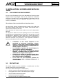
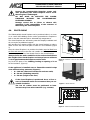
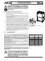
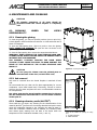
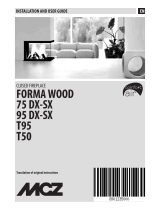
Example of closed fireplace connection
Typical diagram of a correctly laid flue pipe
with a chamber including a sealed hatch to
collect and remove solid materials produced
during combustion positioned at the foot of
the external rising section.
Hood grille
Smoke
connection
Ceramic fibre
insulation
Flue pipe
45° max

FORMA WOOD CLOSED FIREPLACE Chapter 2
USE AND MAINTENANCE MANUAL
page 10
Theoretical recommendations for installation Technical dept. - All rights reserved by MCZ Group S.p.A. - Reproduction prohibited
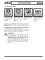
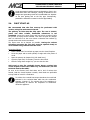
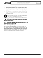
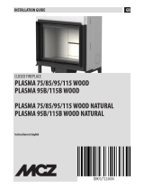
2.5.1. Flue pipe examples
For square- or rectangular-section flue pipes, the internal corners
should be rounded with a radius of no less than 20mm. For the
rectangular cross-section, the ratio between the internal dimensions
should be ≤1.5.
The sections/lengths of the flue pipe shown in the technical data table
are guidelines for correct installation. Any alternative configurations
must be suitably sized in accordance with EN13384-1.
You are advised to fit a chamber to the smoke duct to collect solid
materials located beneath the mouth of the smoke duct. This chamber
should be easy to open and inspect from an airtight flap.
IMPORTANT!
If you have doubts about the performance of your flue pipe
or if the dimensions of the pipe differ from the
recommended values, it is highly advisable to have an
authorised MCZ fitter perform a prior survey and
instrumental measurement of the performance of the flue
pipe (measurement with micro pressure gauge)
MCZ s.p.a. cannot be held liable for closed fireplace
malfunctions caused by the use of a poorly sized flue pipe
installed in a way that does not comply with the requisites
listed herein.
AISI 316 steel flue pipe
with double chamber
insulated with ceramic fibre
or similar, resistant to
400 °C.
EXCELLENT
Refractory flue pipe with
insulated double chamber and
external concrete jacket
lightened with honeycomb
material such as clay.
GOOD
Traditional square-section
clay flue pipe with empty
insulating inserts.
GOOD
Avoid flue pipes with rectangular
cross-sections where the larger
side is twice the smaller one,
such as 20x40 or 15x30.
MEDIOCRE

FORMA WOOD CLOSED FIREPLACE Chapter 2
USE AND MAINTENANCE MANUAL
page 11
Theoretical recommendations for installation Technical dept. - All rights reserved by MCZ Group S.p.A. - Reproduction prohibited
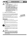
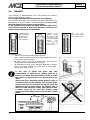
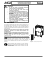
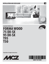
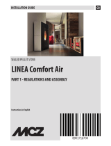
2.6. CHIMNEY
If the chimney is underestimated it can often prevent the "chimney
system" from operating correctly.
The draught of the flue pipe also depends on its chimney.
It is therefore vital that, if the chimney has been hand-crafted, the
development of the four relief sections correspond to more than
twice the internal cross-section of the flue pipe.
As the chimney must always be higher than the ridge of the
roof it will be exposed to wind in all directions. Therefore, an
industrial-type chimney is recommended.
The chimney must:
Have an inner section equal to that of the flue.
Have a working outlet section of at least double that of the
inner section of the flue pipe.
Be built in such a way as to prevent rain, snow and any
foreign bodies from penetrating the flue pipe.
Be positioned so as to ensure adequate dispersion of smoke
and, in all cases, outside the reflux area in which back-
pressures are likely to form.
In the case of paired flue pipes, the solid
combustibility or upper storey chimney shall be at
least 50 cm higher than the others in order to avoid
the transfer of pressure from one paired pipe to the
other.
There must be no obstacles present within a range of
10 linear metres of the chimney. This includes walls,
pitches and trees. If obstacles are present raise the
chimney at least 1 metre above the obstacle and, if
there are other chimneys nearby, space them at least
2 metres apart. In all cases the chimney must
protrude from the ridge of the roof by at least 1 linear
metre.
Industrial chimney
with prefabricated
stacked elements,
allows excellent
smoke discharge.
Traditional hand-
crafted chimney.
The correct outlet
cross-section should
be at least twice the
internal cross-
section of the flue
pipe, ideally 2.5
times its size.
Steel flue pipe
chimney with internal
smoke-deflector cone.
1
m
t
0
,
5
m
t

FORMA WOOD CLOSED FIREPLACE Chapter 3
USE AND MAINTENANCE MANUAL
page 12
Dimensions and technical specifications Technical dept. - All rights reserved by MCZ Group S.p.A. - Reproduction prohibited
3. DIMENSIONS AND TECHNICAL SPECIFICATIONS
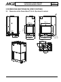
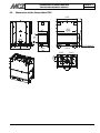
3.1. Dimensions of the Forma Wood 75 rh-lh (fig. shows lh version)
428
2
5
8
Ø244
830
750 rivestimento
705 porta
1
3
8
9
5
8
0
r
i
v
e
s
t
i
m
e
n
t
o
1
3
8
Min.33
max.60
455 porta
583
503
rivestimento
5
5
7
p
o
r
t
a
35
Ø99
72
414
455 door
705
door
503 cladding
750 claddin
g
580 cladding
557 door
Min. 33
max. 60

FORMA WOOD CLOSED FIREPLACE Chapter 3
USE AND MAINTENANCE MANUAL
page 13
Dimensions and technical specifications Technical dept. - All rights reserved by MCZ Group S.p.A. - Reproduction prohibited
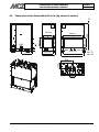
3.2. Dimensions of the Forma Wood 95 rh-lh (fig. shows lh version)
509
72
Ø99
455 porta
4
6
7
p
o
r
t
a
583
503
rivestimento
1025
900 porta
945 rivestimento
1
2
9
9
4
8
8
r
i
v
e
s
t
i
m
e
n
t
o
35
Min.33
max.60
1
3
8
Ø244
525
2
5
8
900 door
455 door
503 cladding
945 cladding
467 door
Min. 33
max. 60
488
cladding

FORMA WOOD CLOSED FIREPLACE Chapter 3
USE AND MAINTENANCE MANUAL
page 14
Dimensions and technical specifications Technical dept. - All rights reserved by MCZ Group S.p.A. - Reproduction prohibited
3.3. Dimensions of the Forma Wood T95
1067
1025
(porta)
1
2
8
8
4
7
1
3
7
1026
(rivestimento)
MIN 33-MAX 60
4
8
9
(
r
i
v
e
s
t
i
m
e
n
t
o
)
514,5 514,5
Ø244
2
6
6
467
porta
4
6
2
p
o
r
t
a
503
rivestimento
583
7
2
513
513
Ø99
(door)
(door)
(cladding)
cladding
door
(cladding)

FORMA WOOD CLOSED FIREPLACE Chapter 3
USE AND MAINTENANCE MANUAL
page 15
Dimensions and technical specifications Technical dept. - All rights reserved by MCZ Group S.p.A. - Reproduction prohibited
3.4. Technical specifications
Technical specifications FORMA WOOD 75 RH-LH
Fuel type Wood
Hourly consumption 3.2 kg/h
(load 2.4 kg in 47 mins)
Nominal heat output kW 10.6 Kcal 9116
Efficiency 78,6%
Heatable volume * 228/40-260/35- 304/30
Recommended draught 12 Pa / 0,12 mbar
Smoke temperature 270 °C
Particulate 73 mg/Nm
3
(13% O
2
)
49 mg/MJ
Smoke outlet diameter 25 cm
Combustion chamber dimensions 60x36 h57
Net weight 300 Kg
External combustion air inlet cm² 100
CO emission in the smoke (13%O
2
) 0.16%
Smoke flow rate 20,1 g/s
Flue Pipe
Up to 5 m. 30x30 cm diameter 30
Over 5 m. 25x25 cm diameter 25
Notes
Intermittent combustion appliance
* These data may vary according to the type of fuel used
Technical specifications FORMA WOOD 95 RH-LH/T95
Fuel type Wood
Hourly consumption 3.4 kg/h
(load 2.6 kg in 47 mins)
Nominal heat output kW 12.3 Kcal 10578
Efficiency 78,6%
Heatable volume * 264/40-302/35- 353/30
Recommended draught 12 Pa / 0.12 mbar
Smoke temperature 280 °C
Particulate 73 mg/Nm
3
(13% O
2
)
49 mg/MJ
Smoke outlet diameter 25 cm
Combustion chamber dimensions 80x36 h48
Net weight 350 Kg
External combustion air inlet cm² 100
CO emission in the smoke (13%O
2
) 0.16%
Smoke flow rate 20,1 g/s
Flue Pipe
Up to 5 m. 30x30 cm diameter 30
Over 5 m. 25x25 cm diameter 25
Notes
Intermittent combustion appliance
* These data may vary according to the type of fuel used

FORMA WOOD CLOSED FIREPLACE Chapter 4
USE AND MAINTENANCE MANUAL
page 16
Installation and assembly Technical dept. - All rights reserved by MCZ Group S.p.A. - Reproduction prohibited
4. INSTALLATION AND ASSEMBLY
IMPORTANT!
The closed fireplace must be positioned and
connected to the smoke duct only by a qualified
technician so that all local and national regulations
are met.
In all cases, the appliance must be installed in
accordance with standard UNI 10683.
When you unwrap the closed fireplace make sure that every part is
in perfect working order and check for any damage caused
during transport. The carrier or retailer must be informed
immediately of any damage.
If the closed fireplace is installed in a place that is difficult to access,
the weight can be lightened by removing the internal elements making
up the combustion chamber. However, we recommend that each
part be correctly repositioned by qualified staff.
MCZ bears no responsibility for failure to adhere to the above
warning.
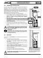
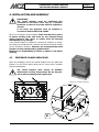
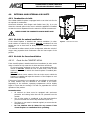
4.1. PREPARATION AND UNPACKING
Open the packaging, remove the closed fireplace from the pallet and
position it in the chosen place, taking care to ensure that it complies
with the specifications.
The closed fireplace must always be handled
VERTICALLY and only using trolleys. Do not drag the
unit as this may damage the support feet.
Example of closed fireplace packaging
A
B

FORMA WOOD CLOSED FIREPLACE Chapter 4
USE AND MAINTENANCE MANUAL
page 17
Installation and assembly Technical dept. - All rights reserved by MCZ Group S.p.A. - Reproduction prohibited
Remove the closed fireplace from the pallet as follows:
Remove plate A by unscrewing the two screws
Remove the two screws from bracket B
Insert the feet or wheels (supplied), by raising them and inclining them
slightly to allow you to extract them. You will then be able to remove
the 4 locking “B” brackets.
Pay particular attention to the door and its glazing to protect them from
mechanical knocks which would compromise their proper working
order.
In all cases, appliances must be handled with care. If possible, unwrap
the closed fireplace near the chosen place of installation.
The materials making up the packaging are neither toxic nor harmful
and, as such, require no special disposal measures.
Storage, disposal and any recycling is the responsibility of the end user,
in compliance with the applicable laws in force.
4.2. OPERATING MODE SELECTION
IMPORTANT!
Decide which system to use before installing the
appliance.
The FORMA system is able to distribute hot air via NATURAL
CONVECTION (COMFORT AIR NV) or FORCED CONVECTION
(COMFORT AIR FV) using a forced ventilation kit.
4.2.1. Natural convection (COMFORT AIR NV)
In natural ventilation air enters the bottom of the closed fireplace
naturally.
4.2.2. Forced convection (COMFORT AIR FV)
If you adopt this system purchase the Comfort Basic Air Kit or optional
Comfort Air Slim kit and follow the instructions provided with each kit.
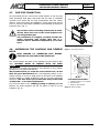
4.3. COUNTERWEIGHT UNLOCKING
The closed fireplace is supplied with the sliding counterweights locked
to prevent dangerous knocks during transport and positioning that may
damage the parts involved in the sliding action, the door and the glass-
ceramic.
To unlock the counterweight and then the door, remove the screws as
shown in
figure 1
from both sides of the closed fireplace in
correspondence with the arrow stickers positioned on both sides.
Figure 1 – Counterweight locking screws

FORMA WOOD CLOSED FIREPLACE Chapter 4
USE AND MAINTENANCE MANUAL
page 18
Installation and assembly Technical dept. - All rights reserved by MCZ Group S.p.A. - Reproduction prohibited
A
A
B
B
Remove the counterweight fastening screws only
after positioning the closed fireplace and to check
that the glass is undamaged.
DO NOT MOVE OR RELOCATE THE CLOSED
FIREPLACE WITHOUT THE COUNTERWEIGHT
FASTENING SCREWS.
Damage caused due to failure to observe this
regulation is the responsibility of the customer of
those using the closed fireplace.
4.4. POSITIONING
The FORMA WOOD closed fireplace can be positioned either in a corner
or on a wall. MCZ cladding can be used to personalise the fireplace or
built on site with materials able to withstand high temperatures.
The closed fireplaces are self-bearing units that simplify installation and
do not require any additional support.
MCZ provides four rotating wheels with the closed fireplace to make it
easier to move the unit to the place in which it is to be installed (
Figure
3).
Once the closed fireplace is in position the wheels must be lifted from
the floor and removed so that the unit is stable on the floor.
To do this, adjust the four feet already fitted on the closed fireplace.
Always assess the static conditions of the surface that will bear
the weight of the closed fireplace and always leave a minimum
5 cm air gap between the fireplace and the walls.
Dry fit the fire plane of the cladding, leaving an opening of 1 cm
for the insulation.
(Figure 2)
If the appliance is installed near to flammable material adopt
some minimal safety measures (Figure 4):
A = 100 mm (distance from the side and rear walls)
B = 50 mm (insulating material)
C = 50 mm (height of the floor)
If the closed fireplace is positioned above a floor or
near to flammable walls we recommend that you use
suitable insulation.
The hot air outlets must be positioned at least
300 mm away from other materials (e.g. curtains).
Figure 2- Distances of the unit from walls and
cladding
Figure 3 – Wheels and feet
5
min
5
min
1
Figure 4 – Distances from flammable materials

FORMA WOOD CLOSED FIREPLACE Chapter 4
USE AND MAINTENANCE MANUAL
page 19
Installation and assembly Technical dept. - All rights reserved by MCZ Group S.p.A. - Reproduction prohibited
C
4.5. ADJUSTING THE HEIGHT AND LEVEL
The Forma Wood closed fireplace is fitted with adjustment feet that
create the right distance between the unit and the floor and adjust the
level of the fire plane of the closed fireplace by approximately 10 cm.
Should you wish to raise the closed fireplace more than 10 cm you
must create a masonry pedestal on which to rest the product. Do not
remove the feet under any circumstances as these are
essential for levelling the appliance. Removal of the feet is
deemed to be a structural modification to the product and, as
such, invalidates the guarantee.
Adjusting the level of the closed fireplace is an
essential operation to allow the fire door to slide
correctly.
If the floor is made from flammable material, the
lower part of the closed fireplace (C) must
be
positioned at least 5 cm away from the floor (
figure
5
).
If the closed fireplace is not level there is a risk that
the door may not close perfectly and the internal
counterweights may bang against the structure
making a noise each time the door is raised and
lowered.
CHECK THE SLIDING ACTION OF THE DOOR A FEW
TIMES BEFORE SEALING THE CLOSED FIREPLACE
WITH THE CLADDING.
We recommend that you use the wheels (supplied) when moving the
closed fireplace. Only the feet are needed to adjust the level.
Figure 5 – Safety measures

FORMA WOOD CLOSED FIREPLACE Chapter 4
USE AND MAINTENANCE MANUAL
page 20
Installation and assembly Technical dept. - All rights reserved by MCZ Group S.p.A. - Reproduction prohibited
4.6. EXTERNAL AND INTERNAL AIR INLETS
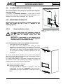
4.6.1. Combustion air inlet
The FORMA WOOD fireplace is equipped with a rear inlet hole for the
air required for combustion.
Connect100 diameter with flanges and flexible hose (fig. 6) to the
external or internal grilles in the room in which the appliance is installed
so that the route is separated from the natural or forced convection air.
NEVER CLOSE THE COMBUSTION AIR INLET HOLE.
4.6.2. Air inlet for natural ventilation
If the closed fireplace is installed with natural ventilation (in other
words without an electric fan) make a 300 cm²
combustion air inlet
behind the unit so that fresh air always flows in beneath the closed
fireplace.
It is essential to adhere strictly to this arrangement otherwise a lack of
oxygen may jeopardise both combustion and the heat output of the
product.
4.6.3. Air inlet for forced ventilation
4.6.3.1.
Ducts for the COMFORT AIR kit
If the closed fireplace is installed with forced ventilation (in other words
using a Comfort Air kit) create the air inlets and ducts as follows:
for correct oxygen exchange in the room, we recommend that you
include a 150 cm²
external air inlet to draw fresh, clean air and
another in the room in which the closed fireplace is installed (also
150 cm²
).
This mode allows correct mixture of the air in the room in which the
fireplace is installed and helps the structure of the fireplace to cool
down more efficiently.
If this type of connection is not possible you are obliged to include both
air inlets, whether they are directed to the outside or the inside.
Depending on the selection, operating temperatures will be slightly
higher or lower than the average. This will not jeopardise the correct
operation of the product.
Remember that:
All external air inlets must be equipped with anti-insect
protection and closing locks that can be operated from the
outside.
The air inlet section is considered to be clear and therefore
you must consider the area of any dimensions (nets etc.)
The filters or nets must be cleaned regularly to ensure that air
can pass freely.
Do not obstruct the air inlets for any reason if the
closed fireplace or ventilation kit is operating.
Figure 6 – Combustion air inlets.
COMBUSTION
AIR INLET
Page is loading ...
Page is loading ...
Page is loading ...
Page is loading ...
Page is loading ...
Page is loading ...
Page is loading ...
Page is loading ...
Page is loading ...
Page is loading ...
-
 1
1
-
 2
2
-
 3
3
-
 4
4
-
 5
5
-
 6
6
-
 7
7
-
 8
8
-
 9
9
-
 10
10
-
 11
11
-
 12
12
-
 13
13
-
 14
14
-
 15
15
-
 16
16
-
 17
17
-
 18
18
-
 19
19
-
 20
20
-
 21
21
-
 22
22
-
 23
23
-
 24
24
-
 25
25
-
 26
26
-
 27
27
-
 28
28
-
 29
29
-
 30
30


MCZ FORMA WOOD 75 DX-SX Use And Installation Manual
- Category
- Fireplaces
- Type
- Use And Installation Manual
- This manual is also suitable for
Ask a question and I''ll find the answer in the document
Finding information in a document is now easier with AI
Related papers
-
 MCZ FORMA WOOD 75 DX-SX Installation and User Manual
-
 MCZ Forma Series Installation and Use Manual
-
 MCZ Forma Wood 95 Use And Installation Manual
-
 MCZ VIVO 90 WOOD Owner's manual
-
 MCZ FORMA WOOD 75 DX-SX Installation and User Manual
-
 MCZ Forma Wood 95 Installation guide
-
 MCZ PHILO COMFORT-AIR Use And Installation Manual
-
 MCZ Saturn Installation and Use Manual
-
 MCZ Powerbox Compact-Link Installation and Use Manual
-
 MCZ LINEA Comfort Air Installation guide


