Page is loading ...

CLOSED FIREPLACE
FORMA WOOD
75 DX-SX
95 DX-SX
T95
T50
INSTALLATION AND USER GUIDE EN
Translation of original instructions

II
TABLE OF CONTENTS
INTRODUCTION ..........................................................................................................1
1WARNINGS AND WARRANTY CONDITIONS .................................................................2
2INSTALLATION INSTRUCTIONS ..................................................................................5
3DIMENSIONS AND TECHNICAL CHARACTERISTICS .....................................................11
4INSTALLATION AND ASSEMBLY ...............................................................................16
5OPERATION ...........................................................................................................23
6MAINTENANCE AND CLEANING ...............................................................................29

1
INTRODUCTION
Dear Customer,
Thank you for having chosen a product from our Wood-burning range.
To allow for optimal product operation and for you to enjoy the warmth and sense of wellbeing that the re can convey in
your home, we advise you to read this manual carefully before starting up the product for the rst time.
REVISIONS TO THE PUBLICATION
The content of this manual is strictly technical and property of MCZ Group Spa.
No part of this manual can be translated into another language and/or altered and/or reproduced, even partially, in another form, by
mechanical or electronic means, photocopied, recorded or similar, without prior written approval from MCZ Group Spa.
The company reserves the right to make changes to the product at any time without prior notice. The proprietary company reserves its
rights according to the law.
CARE OF THE MANUAL AND HOW TO CONSULT IT
t Take care of this manual and keep it in an easily accessible place.
t Should the manual be misplaced or ruined, request a copy from your retailer or directly from the authorised Technical Assistance
Department.
t “Bold text” requires particular attention.
t “Text in “italics” is used to draw your attention to other paragraphs in this manual or any additional explanation.
t “NOTE” provides the reader with additional information.
SYMBOLS USED IN THE MANUAL
ATTENTION:
carefully read and understand the relative message because failure to comply with what is written can
cause serious damage to the product and put the user’s safety at risk.
INFORMATION:
failure to comply with these provisions will compromise the use of the product.
Technical Dept. - All rights reserved - Reproduction is prohibited

2
1WARNINGS AND WARRANTY CONDITIONS
SAFETY PRECAUTIONS
t Installation, functional verication and maintenance must only be performed by qualied or authorised personnel.
t Install the product in accordance with Standards in force in the relative place, region or country.
t This product is not intended for use by persons (including children) with reduced physical, sensory or mental
capabilities, or lack of experience and knowledge, unless they have been given supervision or instruction concerning
use of the appliance by a person responsible for their safety. Errors or incorrect settings can cause hazardous conditions and/
or poor operation.
t Only use fuel recommended by the company. The product must not be used as an incinerator. It is strictly forbidden to use liquid fuel.
t The user, or whoever is operating the product, must read and fully understand the contents of this instruction manual before
performing any operation.
t Do not use the product as a ladder or supporting structure.
t Do not place laundry on the product to dry. Any clothes horses or similar objects must be kept at a safe distance from the product.
Fire hazard.
t "MMMJBCJMJUZGPSJNQSPQFSVTFPGUIFQSPEVDUJTFOUJSFMZCPSOFCZUIFVTFSBOESFMJFWFTUIF.BOVGBDUVSFSGSPNBOZDJWJMBOEDSJNJOBMMJBCJMJUZ
t Any type of tampering or unauthorised replacement with non-original spare parts could be hazardous for the operator's safety and
relieve the company from any civil and criminal liability.
t Most of the surfaces of the appliance can get very hot (door, handle, glass, smoke outlet pipes, etc.). Avoid contact with these
parts unless adequate protective clothing is worn or appropriate means are used, such as heat protective gloves or cold
handle type operating systems.
t It is forbidden to operate the product with the door open or the glass broken.
t Switch the product o in the event of a fault or malfunctioning.
t Do not wash the product with water.
t Do not stand in front of the product for a long time. Do not overheat the room where the product is installed. This could cause injuries
and health problems.
t Do not put any fuel other than wood in the hopper.
t Install the product in rooms that are adequately protected against re and equipped with all the utilities such as supplies (air and
electricity) and smoke outlets.
t If a re breaks out inside the product, switch it o and never open the door. Then contact the competent authorities.
t The product and the ceramic cladding must be stored in a place where there is no humidity and must not be exposed to the elements.
t It is recommended not to remove the feet that support the product in order to guarantee adequate insulation, especially if the
ooring is made of ammable material.
t If the ignition system is faulty, do not force ignition with ammable materials.
t Special maintenance must only be performed by authorised and qualied personnel.
t Assess the static conditions of the surface on which the weight of the product will rest and provide suitable insulation if it is made of
ammable material (e.g. wood, tted carpet or plastic).
t Avoid installing the product in rooms containing B-type gas appliances, hoods with or without an extractor, heat pumps or collective
ventilation ducts.
t Avoid having several closed replaces running at the same time in the room or being close to a stairwell. Furthermore, make sure
there are no appliances in interconnected rooms, which when used simultaneously could cause a negative pressure in one of the
two rooms.
t The product must be used in accordance with all the local and national laws and European Standards applicable in the relative place,
region or country.
t Do not use volatile and/or ammable substances (petrol, alcohol, etc.) to ignite the re.
t Do not use fuel that could release toxic substances or pollutants.
t Do not use water to put the re out.
t Check the external-internal air inlet and the product at least once a year and have them cleaned also.

3
1WARNINGS AND WARRANTY CONDITIONS
INFORMATION
t Please contact the retailer or qualied personnel authorised by the company to resolve a problem.
t Check and clean the smoke outlet pipes regularly (connection with the product).
t The product is not a cooking appliance.
t Keep this instruction manual in a safe place as it must accompany the product throughout its working life. If it is sold or transferred
to another user, always make sure that the manual accompanies the product.
INTENDED USE
5IFQSPEVDUPOMZXPSLTXJUIXPPEBOENVTUCFJOTUBMMFEJOEPPST
WARRANTY CONDITIONS
The company provides a product warranty, excluding the parts subject to normal wear stipulated below, for a period of two years
from the date of purchase, which is proven by a supporting document that contains the name of the seller and the date when the sale took
place. Warranty cover is valid if the completed warranty is returned within 8 days and the product is installed and tested by a qualied
installer, according to the detailed instructions provided in the instruction manual supplied with the product.
The term ‘warranty’ refers to the (free-of-charge) replacement or repairs of parts acknowledged to be faulty due to manufacturing
defects.
RESTRICTIONS
The above-mentioned warranty does not cover parts of electrical and electronic components and fans, which are covered
for two years from when the product is purchased, proof of which is provided as specied above. The warranty does not cover parts
subject to normal wear, such as: gaskets, glass and all parts that can be removed from the rebox.
Replaced parts will be covered by the warranty for the remaining period of the warranty in force as from the date of purchase of the
product.
EXCLUSIONS
Variations in colour of the painted or ceramic parts and crazed ceramics do not constitute grounds for a claim as they are natural
characteristics of the material and product use.
The warranty does not cover any part that may be faulty as a result of negligence or careless use, incorrect maintenance or installation that
does not comply with the company's instructions (see the relative chapters in this user manual).
The company declines all liability for any damage which may be caused, directly or indirectly, to persons, animals or objects as
a consequence of non compliance with all the prescriptions specied in the instruction manual, especially warnings regarding
installation, use and maintenance of the product.
If the product does not work correctly, contact your local retailer and/or importer.
Damage caused during transport and/or when handled is excluded from the warranty.
The supplied manual is the only reference for installation and product use.
The warranty will be rendered null and void in the event of damage caused by tampering, atmospheric agents, natural disasters, electrical
discharges, re, defects in the electrical system and maintenance not being performed at all or as indicated by the manufacturer.
Technical Dept. - All rights reserved - Reproduction is prohibited

4
1WARNINGS AND WARRANTY CONDITIONS
INTERVENTION REQUEST
The company declines all liability if the product and any other accessory is used incorrectly or altered without
authorisation.
All parts must be replaced with original spare parts.
The request must be sent to the retailer who will forward it to the Technical Assistance Service.
SPARE PARTS
Only use original spare parts. The retailer or service centre can provide all the useful information regarding spare parts.
It is recommended not to wait for the parts to be worn before having them replaced. It is important to perform regular maintenance.
PRECAUTIONS FOR CORRECT DISPOSAL OF THE PRODUCT IN ACCORDANCE WITH THE EUROPEAN DIRECTIVE
2002/96/EC AND ITS SUBSEQUENT AMENDMENT 2003/108/EC.
At the end of its working life, the product must not be disposed of as urban waste.
It must be taken to a special dierentiated waste collection centre set up by the local authorities or to a retailer that provides this service.
Disposing of the product separately prevents possible negative consequences for the environment and health deriving from inappropriate
disposal and allows to recycle its materials in order to obtain signicant savings in energy and resources.
As a reminder of the need to dispose of appliances separately, the product is marked with a crossed-out wheeled dustbin.

5
2INSTALLATION INSTRUCTIONS
The requirements stipulated in this chapter refer to the regulations of the Italian installation Standard UNI 10683. In any case, always
comply with the regulations in force in the country of installation.
THE OPERATING ENVIRONMENT
For correct operation and even distribution of heat, the closed replace must be placed where the air required for combustion can ow, in
accordance with the installation regulations and the standards in force in the country of installation.
The volume of the room should be no less than 30 m
3
.
The air must enter through permanent openings in the walls that reach outside with a minimum section of 100 cm
2
in the case of a non-
Oyster installation, i.e. without external ducted combustion air.
These openings must be made in such a way that it is impossible for them to be obstructed in any way.
Air can also be drawn from adjacent rooms to the one that is to be ventilated, provided they have an external air inlet and are not used as a
bedroom or bathroom or where there is a re hazard, such as: garages, timber storerooms, warehouses of ammable materials, observing
under all circumstances the provisions of all the applicable standards in force.
t If the product is placed too close to the wall it could cause overheating and damage the plaster (yellowing,
cracking, etc.).
t The product must be connected to a ue or a vertical duct that can expel the smoke at the highest point of the
building.
t The product must be connected to a ue or an internal or external vertical duct in compliance with current
regulations.
t The smoke derives from the combustion of wood essence and if it comes in contact with or close to walls, the
latter can become dirty.
t The external air inlet must be drilled before positioning the product (except in the case of installation with
Oyster technology).
t The oor of the room where the product will be installed must be adequately sized to withstand its weight.
OUTDOOR AIR INLET
Drill a hole on the outer wall close to the product with a minimum section of 100 cm² (13 cm in diameter or 12x12 cm if square, considering
the protective grids), protected by a grid on the outside.
The air inlet must also:
t be protected with grilles, metal mesh, etc. without reducing the net section;
t be positioned in such a way so as not to be obstructed;
t allow maintenance to be performed;
t be directly interconnected with the room where the product is installed;
t in the case of ducting, up to 3.5 linear metres, increase the cross-section by about 5%, whereas for longer ducts, increase it by 15%.
Remember that the ventilation grilles always show the useful section in cm
2
on one side.
When choosing the grille and size of the hole, check that the useful section of the grille is larger or equal to the
section required by the manufacturer for product operation.
IMPORTANT!
The air ow can also be drawn from an adjacent room to that of the room where the product is installed, provided
the air can ow freely through permanent openings interconnected with the outside; it is forbidden to connect to
thermal units, garages, kitchens or bathrooms.
Technical Dept. - All rights reserved - Reproduction is prohibited

6
2INSTALLATION INSTRUCTIONS
CONNECTION TO THE CHIMNEY
The connection to the closed replace is very important and must be implemented carefully. The products have an upper or rear smoke
exhaust. The smoke exhaust pipe must be assembled in such a way so as to guarantee its tightness during product operation in negative
pressure and prevent condensation from being formed and conveyed towards the product.
Any manual draught control devices inserted in the pipe should not hermetically seal the internal section of the duct. These dampers
must be equipped with a suitable mechanism to prevent the valve from rotating completely in the closed position. The minimum safety
opening surface must be 3% of the through section and not less than 20 cm². If the smoke duct has a horizontal section, the same should
rise with a minimum slope gradient of 3-5% (3-5 cm per every metre).
The horizontal section of the smoke duct must not be longer than 2 m.
It is forbidden to use exible and bre cement pipes. The smoke duct must not cross rooms in which it is forbidden to
install combustion appliances. It is forbidden to use counter-sloping pipes.
&9".1-&0'$0//&$5*0/505)&$)*./&:

7
2INSTALLATION INSTRUCTIONS
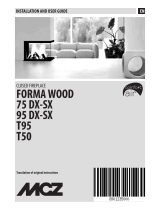
&9".1-&0'$-04&%'*3&1-"$&$0//&$5*0/
"$&3".*$'*#3&*/46-"5*0/
#4.0,&'*55*/(
$$)*./&:'-6&
%)00%(3*--&
5:1*$"- 3&13&4&/5"5*0/ 0' " $033&$5-: */45"--&%
'-6&1*1&8*5)"55)&'0050'5)&&95&3/"-3*4*/(
4&$5*0/5)&104*5*0/*/(0'"$)".#&38*5)"4&"-&%
%003 50 $0--&$5 "/% 3&-&"4& 5)& 40-*% ."5&3*"-4
130%6$&%%63*/($0.#645*0/
CHIMNEY
The chimney is the fundamental element for smoke expulsion and must therefore comply with the following requirements:
t be waterproof and thermally insulated.
t Be made of suitable materials that resist mechanical stress over time, heat, the eects of the combustion products and any possible
condensation.
t Have a vertical set-up with deviations from the axis of no more than 45° and free of bottlenecks.
t Must be suitable for the specic operating conditions of the product and have the CE marking (EN1856-1, EN1443).
t Must be adequately sized for the draught/smoke expulsion requirements that are necessary for the product to operate correctly
(EN13384-1).
t The chimney must not be shared with other appliances.
t The product must be at least category T400 (or higher if required by the smoke temperature of the appliance) and soot-re resistant.
Resistance to moisture is mandatory if this is required by the product size.
t The internal section is preferably circular.
t In the case of a pre-existing product that has been used, it must be cleaned.
The product is fundamental for correct operation and safety of your product.
In the event of poor weather conditions for product operation (low pressure, external temperature not particularly
harsh, windy day), inverse draught may occur in the product. In this case, it is recommended to use a little paper to
ignite the re to heat the product and restore normal draught. Then proceed with normal product start-up.
Technical Dept. - All rights reserved - Reproduction is prohibited

8
2INSTALLATION INSTRUCTIONS
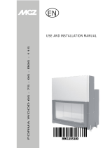
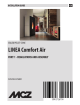
EXAMPLES OF CHIMNEYS
AISI 316 steel product with
double chamber insulated
with ceramic bre or similar
material, resistant to 400°C.
Refractory product with
insulated double chamber and
external lightweight concrete
cladding with cellular material
such as clay.
Traditional square-section clay
product with insulating empty
inserts.
Avoid products with an internal
rectangular section where the
larger side is 1.5 times the
smaller side (such as 20x40 or
15x30).
EXCELLENT GOOD POOR VERY POOR
For square or rectangular-section chimneys, the internal corners must be rounded with a radius of no less than 20 mm. For a rectangular
section, the ratio between internal dimensions must be ≤1.5.
The sections/lengths of the chimneys shown in the technical data table are guidelines for a correct installation. Any alternative
congurations must be suitably sized in accordance with the general method of calculation of UNI EN13384-1.
It is recommended for the ue duct to be equipped with a chamber to collect solid materials beneath the opening of the smoke duct,
which can be easily opened and inspected through an airtight door.
Should doubts arise regarding product performance or if its dimensions are dierent from those recommended, you
are strongly advised to have an installer, authorised by the manufacturer, perform an inspection and evaluate the
performance of the product.
The manufacturer declines all liability regarding product malfunctioning if this is attributable to a product that is
badly sized and installation does not comply with the stipulated requirements.

A
B
1 mt
0,5 mt
9
2INSTALLATION INSTRUCTIONS
CHIMNEYPOT
Often, if this factor is underestimated it hinders smooth "product system" operation.
The draught of the chimney also depends on its chimneypot.
In the case of an artisan product, it is very important for the four expulsion sections to be more than twice the internal section of
the product.
The chimneypot will be exposed to the four winds and it is therefore recommended for it to be specically designed to
withstand the elements (e.g. an industrial product).
*/%6453*"-$)*./&:8*5)13&'"#3*$"5&%45"$,&%
&-&.&/54"--084&9$&--&/54.0,&%*4104"-
53"%*5*0/"-)"/%$3"'5&%$)*./&:
5)&$033&$5&916-4*0/4&$5*0/.645#&"5-&"45
58*$& 5)& */5&3/"- 4&$5*0/ 0' 5)& 130%6$5
*%&"--:5*.&4*544*;&
$)*./&:105 '03 " 45&&- 130%6$5 8*5) "/
*/5&3/"- $0/& "/% 4.0,& %&'-&$503 "--084
&9$&--&/54.0,&%*4104"-
The chimneypot must comply with the following requirements:
t have an internal section equal to that of the product.
t Have a useful outlet section that is at least double that of the internal section of the product.
t Be constructed in such a way so as to prevent rain, snow and any foreign body from entering the product.
t Be positioned so as to ensure adequate smoke dispersion and in any case beyond the reux area in which counter pressure is likely
to form.
:&4
"611&3-&7&-0340-*%
$0.#645*#*-*5:
#-08&3-&7&-
/0
Technical Dept. - All rights reserved - Reproduction is prohibited

10
2INSTALLATION INSTRUCTIONS
In the case of paired products, the solid combustibility or upper storey chimneypot must be at least 50 cm higher than the
others in order to prevent the pressure from being transferred between the paired chimneypots.
The chimneypot must not have any obstacles within a range of 10 metres, such as walls, slopes and trees. Otherwise, raise
it by at least 1 m above the obstacle and in the case of other chimneypots nearby, leave a gap of at least 2 m. In any case,
the chimneypot must exceed the highest point of the roof by at least 100 cm or be above the reux area, which is equal to
130 cm in roofs with a gradient greater than 10° (height perpendicular to the surface of the roof).

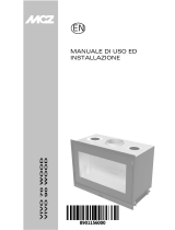
168
405
672
47
138
580
MIN.33
MAX60
1389
706
407
258
ø244
457
553
503
584
414
72
ø99
11
3DIMENSIONS AND TECHNICAL CHARACTERISTICS
FORMA WOOD 75 DX-SX DIMENSIONS (SX - LEFT VERSION IN FIGURE)
Technical Dept. - All rights reserved - Reproduction is prohibited

167.5
509
471299
673
488
138
945
MIN 33
MAX 60
1024
ø244
504.5
258.5
ø100
509
72
503
583
12
3DIMENSIONS AND TECHNICAL CHARACTERISTICS
FORMA WOOD 95 DX-SX DIMENSIONS (SX - LEFT VERSION IN FIGURE)

266
520
520
1026
ø250
1024
489
662
1346
137
MIN 33
MAX 60
59
169
520
520
503
584
463
467
ø100
513
105
13
3DIMENSIONS AND TECHNICAL CHARACTERISTICS
FORMA WOOD T95 DIMENSIONS
Technical Dept. - All rights reserved - Reproduction is prohibited

ø250
252
252
339
980
825
746
127
ø99
258
258
ø100
252
252
245.5
556
572
486
614
591
55
173
520
MIN 47
MAX 67
14
3DIMENSIONS AND TECHNICAL CHARACTERISTICS
FORMA WOOD T50 DIMENSIONS

15
3DIMENSIONS AND TECHNICAL CHARACTERISTICS
TECHNICAL CHARACTERISTICS
TECHNICAL CHARACTERISTICS FORMA WOOD 75 DX-SX FORMA WOOD 95 DX-SX/T95 FORMA T50
Type of fuel Wood Wood Wood
Hourly consumption 3.2 kg/h
(2.4 kg load in 47 min)
3.4 kg/h
(2.6 kg load in 47 min)
3.4 kg/h
(2.6 kg load in 47 min)
Nominal heat output power: kW 10.6 Kcal 9116 kW 12.3 Kcal 10578 kW 11 Kcal 9460
Eciency 78,6% 78,6% 79,0%
Heatable volume m
3
228/40–260/35–304/30 264/40–302/35–353/30 237/40-270/35-315/30
Recommended draught 12 Pa / 0.12 mbar 12 Pa / 0.12 mbar 12 Pa / 0.12 mbar
Smoke temperature 270 °C 280 °C 250°C
Particulate 73 mg/Nm3 (13% O2)
49 mg/MJ
73 mg/Nm3 (13% O2)
49 mg/MJ
73 mg/Nm3 (13% O2)
49 mg/MJ
Smoke outlet Ø 25 cm Ø 25 cm Ø 25 cm
Firebox dimensions 60x36 H57 cm 80x36 H48 cm 29X67 H63 cm
Net weight 300 kg 350 kg 320 kg
External combustion air inlet 100 cm
2
100 cm
2
100 cm
2
CO emission in the smoke (13% O
2
) 0,16% 0,16% 0,14%
Smoke ow rate 20.1 g/s 20.1 g/s 20.1 g/s
Flue
Up to 5 m 30x30 cm Ø30 30x30 cm Ø30 30x30 cm Ø30
Over 5 m 25x25 cm Ø25 25x25 cm Ø25 25x25 cm Ø25
Notes
The stove is an intermittent combustion appliance.
* These data may vary according to the type of fuel used.
Tested according to EN 13240 in accordance with Directive 89/106/EEC (Construction Products)
Technical Dept. - All rights reserved - Reproduction is prohibited

B
A
16
4INSTALLATION AND ASSEMBLY
IMPORTANT!
The closed replace must be installed and connected to the ue duct exclusively by a specialised technician, in order
for all local or national regulations to be complied with. Installation must in any case be in accordance with UNI
10683.
When the closed replace is unpacked, check that every part is in perfect working order and no damage has been caused during transport.
Any damage must immediately be reported to the carrier or dealer.
If the closed replace is installed in a place that is dicult to access, the weight can be reduced by removing the internal elements of the
rebox, but it is recommended to put all elements back in place properly and have this operation carried out exclusively by specialised
personnel.
The manufacturer declines all liability if the warning above is not complied with.
PREPARATION AND UNPACKING
Open the package, remove the closed replace from the pallet and set it in the pre-selected place, making sure this complies with the
requirements.
The closed replace must always remain in a VERTICAL position and handled solely with a cart. Do not drag the unit
which could suer damage to the support feet.
To remove the closed replace from the pallet act as follows:
t Remove plate A by removing the screws
t Remove the two screws from bracket B
One can then remove the 4 locking brackets "B", after having inserted the feet or wheels (supplied), raising them and tilting them slightly
to enable extraction. Pay particular attention to the door and its glass, protecting them from mechanical knocks that would compromise
their integrity.
Always handle the products with care. If possible, unpack the closed replace near the area
it will be installed in.
The packaging materials are neither toxic nor harmful, and therefore no particular disposal measures are required.
Storage, disposal or any recycling is under the responsibility of the end user in compliance with the applicable laws in force.
#-0$,*/(1-"5&4"/%#3"$,&54
&9".1-&0'$-04&%'*3&1-"$&1"$,"(&

17
4INSTALLATION AND ASSEMBLY
CHOICE OF OPERATING MODE
IMPORTANT!
Before installation one must decide which system to use.
The FORMA has the possibility to distribute hot air according to the NATURAL CONVECTION (COMFORT AIR VN) method or FORCED
CONVECTION (COMFORT AIR VF) method via a forced ventilation kit.
Natural convection (COMFORT AIR VN)
In the case of natural ventilation, air enters naturally in the lower part of the closed replace.
Forced convection (COMFORT AIR VF)
If one uses this system, purchase the Comfort Basic Air Kit or the Comfort Air Slim optional kit and follow what is specied in the
instructions contained in each kit.
COUNTERWEIGHTS UNLOCKING
The closed replace is supplied with the sliding counterweights locked to prevent dangerous knocks that could damage the sliding parts,
door and ceramic glass during transportation and positioning.
To unlock the counterweights and therefore the door, remove the screws as shown in gure 1 from both sides of the closed replace in
correspondence of the stickers with arrows placed on both sides.
Remove the counterweights xing screws only after having positioned the closed replace and to check that the
glass is intact.
DO NOT HANDLE NOR MOVE THE CLOSED FIREPLACE WITHOUT THE COUNTERWEIGHTS FIXING SCREWS.
Damage caused by failure to comply with this rule is under the responsibility of the customer or whoever represents
him.
'*(63&ű$06/5&38&*()54#-0$,*/(4$3&8
Technical Dept. - All rights reserved - Reproduction is prohibited

18
4INSTALLATION AND ASSEMBLY
POSITIONING
The FORMA WOOD closed replace may be positioned both at an angle or against a wall. One can customise it with the manufacturer's
claddings or build them on site with materials resistant to high temperatures.
The closed replaces are freestanding units that simplify installation and that do not require any additional support. To facilitate moving
the unit to the point in which it must be installed, the manufacturer supplies the closed replace with four swivel wheels that make
moving the closed replace easier and not tiring. (gure 2)
Once the closed replace has been positioned, the wheels must be lifted from the ground or removed, so that the unit is stable on the oor.
This is possible by adjusting the four feet pre-mounted on the closed replace.
Always assess the static conditions of the surface on which the weight of the product will rest and always leave a gap of
at least 5 cm between the chimney and walls.
Dry mount the hearth of the cladding, leaving a 1 cm gap for insulation. (Figure 3)
MINIMUM DISTANCES
FORMA WOOD
75 DX-SX
95 DX-SX
T95
T50
Non-ammable walls Flammable walls
A = 50 mm
B = 20 mm
C = 20 mm
A = 100 mm
B = 50 mm
C = 50 mm
A = distance from the side and rear walls
B =insulating material
C = height from oor
If the closed replace is positioned on a oor or in proximity of ammable walls one recommends suitable insulation.
The hot air outlet vents must be positioned at least 300 mm away from other materials. (e.g. curtains)
'*(63&ū8)&&-4"/%'&&5 '*(63&ū%*45"/$&0'5)&6/*5'30.5)&8"--4
"/%'30.5)&$-"%%*/(
/