NEC NP-PX602UL-BK Installation and Setup Guide

Category
Projector mounts
Type
Installation and Setup Guide

NEC NP-PX602UL-BK offers easy and flexible installation options for various applications with its adjustable feet and versatile mounting possibilities. Whether you prefer tabletop placement or ceiling mounting, this projector adapts to your needs. Additionally, its compact size and lightweight design make it portable for convenient use in different locations.

NEC NP-PX602UL-BK offers easy and flexible installation options for various applications with its adjustable feet and versatile mounting possibilities. Whether you prefer tabletop placement or ceiling mounting, this projector adapts to your needs. Additionally, its compact size and lightweight design make it portable for convenient use in different locations.

1 of 8
ISSUED: 09-15-11 SHEET #:125-9244-1
Model: NP750CM
Installation and Assembly:
Projector Adapter Plate
• Itistheresponsibilityoftheinstallertoensure
thattheprojectorisproperlyventilated.Spacers
areprovidedtoraisethemountofftheprojector
surface.
CAUTION
• Installermustverifythattheceilingwillsafely
supportfourtimesthecombinedweightofall
attachedequipmentandhardware.
WARNING
Model: PX750CM
Installation and Assembly:
Adapter Plate for NEC Projector
Model PX-750U
IMPORTANT! Read entire instruction sheet before you start installation and assembly.
Max Load Capacity:
60lb(22.3kg)
2 of 8
ISSUED: 09-15-11 SHEET #:125-9244-1
A
NOTE: Readentireinstructionsheetbeforeyoustartinstallationandassembly.
Beforeyoustartmakesureallpartslistedareincludedwithyourproduct.
B C D
E F G
H I
J
K
L
M
N
R
Description Qty. Part #
A adapterassembly 1 056-1061
B M4x12mmsocketpinserratedwasherheadscrew 4 510-1079
C M5x10mmsocketpinserratedwasherheadscrew 4 510-1126
D M4x40mmsocketpinserratedwasherheadscrew 2 510-1091
E 4mmallenwrench 1 560-9646
F .375spacer 2 590-1140
G .75spacer 2 590-1300
H projectormountassembly 1
055-1950
I columnconnector 1 580-1025
J
ceilingplate 1
580-1042
K
.25"x.5"x.25"spacer
2 590-1050
L
#10-32x3/8"thumbscrew
1 560-1107
M
#10-32x3/8"socketpinserratedwasherheadscrew
1 520-1151
N
10-32x3/8"slottedsetscrew
3 520-1187
O
concreteanchor
2 590-0320
P
#10-32x3/8"socketpinscrew
2 520-1084
Q
#14x2.5"woodscrew
2 5S1-015-C03
R
5mmallenwrench
1 560-0216
S
M5x10mmtype-Fscrew
1 520-1164
Parts List
P
Q
O
S
3 of 8
ISSUED: 09-15-11 SHEET #:125-9244-1
J
Q
Drilltwo5/32"(4mm)dia.holestoaminimum
depthof2.5"(64mm).Attachceilingplate(J)
toceilingwithtwo#14x2.5"woodscrews(Q)
using3/8"(10mm)socketwrenchasshownin
gure1.1.
NOTE:Foroptionalcordmanagement,install
twospacers(K)betweenceilingplate(J)and
ceilingasshowningure1.2.
Skip to step 2 for ush mount installation.
Skip to step 3 for extension column installation.
Installation To Wood Joist Finished Ceilings, Exposed Wood Joists,
or Wood Beam Ceilings
• Tightenwoodscrewssothatceilingplateisrmly
attached,butdonotovertighten.Overtighteningcan
damagethescrews,greatlyreducingtheirholding
power.
• Nevertighteninexcessof80in•lb(9N.M.).
• Makesurethatmountingscrewsareanchoredinto
thecenterofthestuds.Theuseofan"edgetoedge"
studnderishighlyrecommended.
• Itistheresponsibilityoftheinstallertoverifythatthe
supportingsurfacewillsafelysupportthecombined
loadofallattachedhardwareandcomponents.
WARNING
1
IMPORTANT:BesuretodrillholesintothejoistCENTER!
WOODJOIST
WOODJOIST
CEILING
CEILING
J
Q
K
g. 1.1
g. 1.2
4 of 8
ISSUED: 09-15-11 SHEET #:125-9244-1
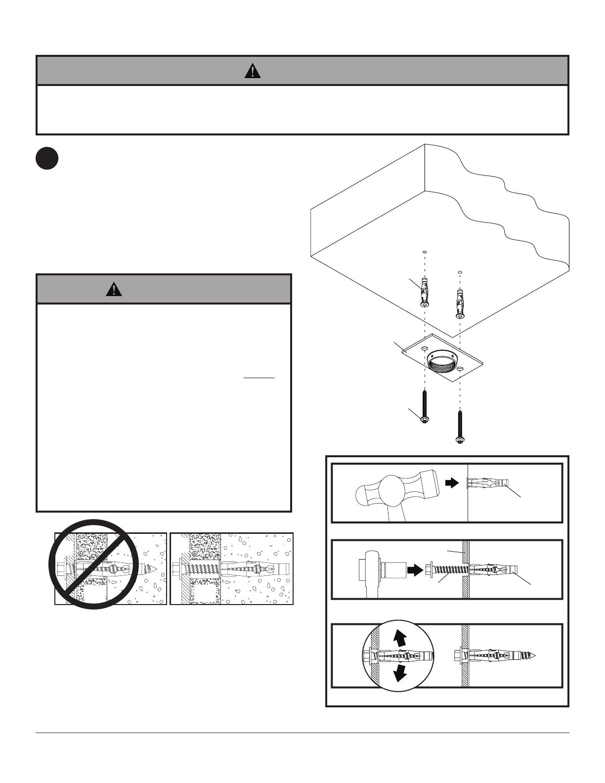
Installation to Concrete Ceilings
• Tightenwoodscrewsrmly,butdonotovertighten.
Overtighteningcandamagethescrews,greatly
reducingtheirholdingpower.
• Nevertighteninexcessof80in•lb(9N.M.).
• Alwaysattachconcreteexpansionanchorsdirectly
toload-bearingconcrete.
• Neverattachconcreteexpansionanchorstocon-
cretecoveredwithplaster,drywall,orothernishing
material.Ifmountingtoconcretesurfacescovered
withanishingsurfaceisunavoidable,thenish-
ingsurfacemustbecounterboredasshownbelow.
Besureconcreteanchorsdonotpullawayfrom
concretewhentighteningscrews.Ifplaster/drywall
isthickerthan5/8"(16mm),customfastenersmust
besuppliedbyinstaller.
WARNING
• Concretemustbe2000psidensityminimum.Lighterdensityconcretemaynotholdconcreteanchor.
• Installermustverifythatthesupportingsurfacewillsafelysupportthecombinedloadoftheequipmentandallat-
tachedhardwareandcomponents.
WARNING
Drilltwo5/16"(8mm)dia.holestoaminimumdepth
of2.5"(64mm).Insertanchors(O)inholesushwith
wall.Placeceilingplate(J)overanchorsandsecure
usingtwo#14x2.5"screws(Q).
IMPORTANT:Itistheresponsibilityoftheinstallerto
verifythattheceilingwillsafelysupportthecombined
loadofallattachedhardwareandcomponents.
Skip to step 2 for ush mount installation.
Skip to step 3 for extension column installation.
1
SOLID
CONCRETE
CEILING
1
3
2
Drillholesandinsertanchors(O).
Placeplate(B)overanchors(S)andsecurewithscrews(Q).
Tightenallfasteners.
J
Q
concrete
surface
CUTAWAY VIEW
INCORRECT CORRECT
wall
plate
wall
plate
plaster/
drywall
plaster/
drywall
concrete
concrete
J
O
O
O
Q
5 of 8
ISSUED: 09-15-11 SHEET #:125-9244-1
Handthreadprojectormountassembly(H)intoceilingplate(J)asshowningure2.1.Alignthenotchofprojector
mountassemblywithoneofthefourholesinceilingplate(J)andsecurewithanM5x10mmsocketpinscrew(S)
asshownindetail1.
NOTE:Slottedsetscrew(N)isusedtojamagainstthethreadsoftheprojectormountassemblytopreventany
excessmovementoftheprojectormountassembly(H).Donotovertightenscrew;overtighteningscrewwilldamage
threadsmakingitdifculttoseparateprojectormountassemblyfromceilingplate.
Flush Mount Installation
2
g. 2.1
DETAIL 1
J
S
N
H
NOTCH
6 of 8
ISSUED: 09-15-11 SHEET #:125-9244-1
Extension Column Installation
Handthreadextensioncolumnintoceilingplace(J).
Alignnotchofextensioncolumnwithoneofthefour
holesinceilingplate(J)andsecurewithan
M5x10mmsocketpinscrew(S)usingallenwrench
(E)asshownindetail2.
Handthreadcolumnconnector(I)ontoextension
column.Alignslotinextensioncolumnwithoneof
thetopholesofthecolumnconnector(I).Insert
andtightenone#10-32x3/8"socketpinscrew(P)
throughcolumnconnector(I)intoslotofextension
columnusing4mmsecurityallenwrench(O)as
shownindetail3.
Handthreadprojectormountassembly(H)into
columnconnector(I).Alignslotofprojectormount
assembly(H)withoneofthebottomholesincolumn
connector(I).Insertandtightenone#10-32x3/8"
socketpinscrew(P)throughcolumnconnectorinto
projectormountassemblyusing4mmsecurityallen
wrench(E)asshownindetail4.
NOTE:Slottedsetscrews(N)areusedtojam
againstthethreadsofeachconnectingjointto
preventanyexcessmovement.Donotovertighten
screw.Overtighteningscrewwilldamagethreads
makingitdifculttoseparatecomponents.
3
g. 3.1
DETAIL 2
DETAIL 3
DETAIL 4
P
N
N
P
I
H
EXTENSION
COLUMN(SOLD
SEPARATELY)
(ULLISTEDEXT
ORADJSERIES)
S
N
J
7 of 8
ISSUED: 09-15-11 SHEET #:125-9244-1
FRONTOF
PROJECTOR
4
Handlescanbepulledoutforadditionalleverageas
shownbelow.
5
Handlescanbesecuredtoadapterassembly
(A)usingfourM5x10mmsocketpinserrated
washerheadscrews(C)asshownbelow.
6
FRONTOF
PROJECTOR
FRONTOF
PROJECTOR
FRONTOFPROJECTOR
M4X40MMSOCKETPINSERRATED
WASHERHEADSCREW(D),WITH
SPACERS(F AND G)
M4X12MMSOCKETPINSERRATED
WASHERHEADSCREW(B)
A
B
C
D
F
G
A
HANDLE
Fastenadapterassembly(A)tobottomofprojectorusingtwoM4x40mmsocketpinserratedwasherhead
screws(D)withspacers(F and G),andfourM4x12mmsocketpinserratedwasherheadscrews(B)in
orientationasshownbelow.
8 of 8
ISSUED: 09-15-11 SHEET #:125-9244-1
©2011,PeerlessIndustries,Inc.Allrightsreserved.
Allotherbrandandproductnamesaretrademarksorregisteredtrademarksoftheirrespectiveowners.
Attaching Adapter Plate to Projector Mount
Attachprojectortoprojectormountassembly(H)
byinsertingthemountintotheadapterplateand
twistinguntiltheadapterplatewillnolongerturn.
Thespringloadedcaptivescrewshouldlineupwith
acorrespondingholeontheadapterplate.Push
downandtightenthespringloadedcaptivescrewto
securetheadapterplatetothemount.Ifnotusing
theoptionalsecurityfeature,fastenthumbscrew(L)
intheholeoppositethespringloadedcaptivescrew.
OPTIONAL:ForArmorLock™security,insert
#10-32x3/8"serratedwasherheadscrew(M)in
theholeoppositethespringloadedcaptivescrew.
Tightenwith4mmsecurityallenwrench(E).This
willpreventtheprojectorfrombeingremoved.
Useknobstoadjustprojectormountrollandpitch.
Knobsalsomaybeadjustedusingallenwrenches
(E,R).
Tightensocketpinscrewusingallenwrench(E)to
lockrollandpitchposition.
7 8
CAPTIVE
SCREW
H
PROJECTOR
ROLL
ADJUSTMENT
KNOB
PITCH
ADJUSTMENT
KNOB
SOCKET
PIN SCREW
L
M
  • Page 1 1
  • Page 2 2
  • Page 3 3
  • Page 4 4
  • Page 5 5
  • Page 6 6
  • Page 7 7
  • Page 8 8

NEC NP-PX602UL-BK Installation and Setup Guide

Category
Projector mounts
Type
Installation and Setup Guide

NEC NP-PX602UL-BK offers easy and flexible installation options for various applications with its adjustable feet and versatile mounting possibilities. Whether you prefer tabletop placement or ceiling mounting, this projector adapts to your needs. Additionally, its compact size and lightweight design make it portable for convenient use in different locations.

Ask a question and I''ll find the answer in the document

Finding information in a document is now easier with AI