Page is loading ...

Model 8226 GNSS Surge Suppressor
Installation Guide
Orolia recommends the use of
an inline coaxial protector for all
products connected to an outside
GNSS antenna.
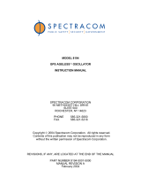
Orolia oers the Model 8226 GNSS
Antenna Surge Suppressor to
protect a connected GNSS receiver
from damaging voltages occurring
on the antenna coax cable. Voltages
exceeding the impulse suppressor
trip point are shunted to the system
ground. The Model 8226 is designed
to withstand multiple surges.
Figure 1-1: 8226 Surge supressor with bracket

Model 8226 GNSS Surge Suppressor
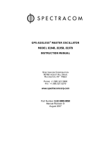
1. Mounting Bracket Installation
Install the suppressor indoors, preferably where the coax enters the building. Connect the largest- gauge
grounding wire available to the mounting bracket, using the M8 attachment screw; see Fig. 1-2:
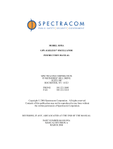
2. Grounding Plate Installation
Optionally, the suppressor can be mounted to a grounding panel or bulkhead, as shown in Fig. 1-3: Orolia
oers a Surge Protector Grounding Kit, part number 8226-0002-0600, that serves as a single point ground
connection for the Model 8226 Surge Suppressor.
The kit includes a copper grounding plate on melamine-covered particle board, mounting hard ware, copper
strapping, strap clamps, ground wire, a ground clap, copper paste, an appro priate mounting bracket, and
ancillary hardware. A single point ground system is recommended to provide optimum protection from
lightning strikes.
GPS RECEIVER
SURGE
SUPPRESSOR
BRACKET
EXPOSED
CABLE RUN
GROUND/EARTH
CONNECTION(S)
GPS
ANTENNA
Use M8
mounting
screw
to attach
ground wire
Nut
Washer
Bracket
Arrestor
Figure 1-2: Model 8226 with optional mounting bracket

Model 8226 GNSS Surge Suppressor
• Mount the grounding panel indoors, preferably close to where the antenna coax enters the building and
direct access to the system ground is available.
• The grounding panel must be connected to a low impedance (both low resistance and low inductance)
ground system to assure proper operation of the surge protection equipment. To minimize the inductance
between the ground plate and system ground interconnection, keep the copper grounding strap as straight
as possible.
• Limit bends to a radius of 8 inches or larger. Thoroughly clean the copper panel to remove any oxidation
or contaminants prior to installation. Apply the supplied copper paste to all junctions on the copper panel
to maintain a low-impedance connection.
Figure 1-3: Grounding kit panel installation
Each Model 8226 includes two clamp type male N connectors. These connectors can be used to splice the
Model 8226 into the antenna coax. The connectors are compatible with Orolia CAL7xxx cable assemblies and
Times Microwave LMR- 400 equivalent coax. Connector assembly instructions are shown below:

Model 8226 GNSS Surge Suppressor
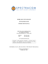
3. Assembly Instructions, Type N Connectors, and Clamps
The instructions below apply to Type N Connectors, part number P051-0001-0100.
Using the manufacturer’s part list, verify that all the connector parts are included. (See also connector diagram
below.)
4. Document Revision History
Revision ECO Description Date
A – Legacy documentation
B 2017
Reformatted instructions for latest style standards. Made minor text edits thhroughout. Added reference to Grounding Kit,
8226-0002-0600
Feb. 2007
C 2333 Updated Figure 1 to accurately represent new hardware. June 2009
D 2621 Minor maintenance & adjustments made to reect hardware changes (cable jacket dimensions). April 2011
E 2715 Update Figure 1, additional minor document maintenance. August 2011
6 0445 Connector assembly instructions revised. Sept 2015
7 0121 Changed arrestor model and instructions for grounding. Plus: Layout and minor content modications. Nov. 2017
BRACKET
PLUG BODY MALE CONTACT CLAMP GASKET WASHER NUT
Figure 1-4: Connector component;
and below Table 1-1: Connector
Assembly
Cable Assembly Instructions - Clamp
Step 1
Stripping Braid Wire
Strip the braid wire where the connectors will be installed. Strip the
cable as shown in illustration on the right; follow the cable stripping
dimensions as recommended by the connector manufacturer.
Step 2
Nut, Washer, Gasket, and Clamp
Place all the parts in order and make sure the assembly direction is
correct.
Step 3
Spreading Braid Waire and Stripping Inner conductor:
Fold the braid wire backward onto the braid clamp and make it spread
evenly:
Step 4
Contact Pin Soldering
While soldering the contact pin, it must be soldered carefully, and the
pin must remain free of tin-solder.
Step 5
Fastening the Nut
Install metal screw onto nut, and spin into the connector body until
hand-tight.
Use Wrench and tighten the nut.
13 July, 2020. Model 8226 GNSS Surge Suppressor
Specications subject to change or improvement without notice
© 2020 Orolia
www.orolia.com
sales@orolia.com
/