Page is loading ...

For Helmets Equipped with
Ops-Core Accessory Rail Connectors (ARCs)
UM-1033 REV. D
Copyright © 2018 Gentex Corporation. Ops-Core and the Ops-Core logo are registered trademarks of Gentex Corporation or its afliates.
UNIVERSAL
STEP-IN VISOR
OPERATOR’S MANUAL


TABLE OF CONTENTS
Introduction
Visor Installation
Visor Positions
Engaged Position
NVG Compatibility
Stowed Positions
Visor Features
Gasket Removal
Bungee Tightening & Loosening
Lens Replacement
Bungee Replacement
Lens Care
Warranty
4
5
6
6
6
7
8
8
9
10
12
14
15
3

INTRODUCTION
ABOUT YOUR OPS-CORE UNIVERSAL STEP-IN VISOR
The Universal Step-In Visor system is specically designed to be used with NVGs, but it can also be used without
NVGs. This system is compatible with all FAST, SENTRY, and ACH/TBH helmets equipped with Ops-Core Accessory
Rail Connectors (ARCs). The close-tting lens provides protection while not compromising the functionality of
NVGs. The visor is also equipped with a removable gasket system to provide scalable protection from debris and
brown out conditions. The clear lens can also be swapped out for a variety of different lenses depending on the
condition of your mission.
UNIVERSAL STEP-IN VISOR INCLUDES:
Universal Step-In Visor
Spare Lens
(Not included in single lens kits)
Lens Care Cloth
Small
Rail Clips
Large
Rail Clips
4

PRE-INSTALLATION
Before the Universal Step-In Visor can be properly installed you must install the compatible rail clip depending
on the rail system you are using.
VISOR INSTALLATION
Compatible with
FAST High Cut ARCs
FAST Super High Cut ARCs
Sentry ARCs
Compatible with
ACH ARCs
ACH Skeleton ARCs
FAST Super High Cut Skeleton ARCs
2
INSTALL COMPATIBLE
RAIL CLIPS
Guide the rail clip into the front of the rail dove tail
and press rmly to lock it into place. Repeat this for
the other side.
3
ALIGN VISOR AND
HELMET SHELL
Align the visor to the center of the helmet by using
the NVG shroud.
3
ATTACH VISOR BUNGEES TO
RAIL CLIPS
Pull the bungee strap towards the rail clip and secure
it by pressing the bungee strap clip into the rail clip.
Repeat this for the other side.
Small Clip Large Clip
5

VISOR POSITIONS
ENGAGED POSITION
The visor can be positioned in a variety of different positions. The engaged position provides the most protection
and should be used for training and real-time missions.
NVG COMPATIBILITY
The Universal Step-In Visor is designed to t close
to the eyes which allows it to t behind NVGs. This
provides protection during night time missions.
6

VISOR POSITIONS
STOWED POSITIONS
The visor can be stowed in a variety of different positions. This allows the user to reposition the Universal Step-In
visor during non-combat scenarios for comfort and donning and dofng the helmet.
STOWED (MID)
This position should be used when donning/
dofng the helmet. The position also allows the
user to wipe their eyes and easily adjust their
chinstrap system.
STOWED (UP)
This position is typically used when the Step-In
Visor is not needed but still needs to be attached
to the helmet for quick deployment. This position is
also compatible while wearing NVGs.
The Step-In Visor can also be attached to the
helmet Velcro via the hook and loop system on the
bungee tabs. This allows the user to quickly stow
the visor while wearing NVGs.
7

NOTE:
Make sure to keep the nose piece in place
during normal use to prevent the lens edge from
bottoming out on your nose. The nose piece is
removable for cleaning purposes.
To remove the Side Debris Gaskets grab the rubber tab and pull to the side rst, then pull downward in a circular
motion. Repeat this step for the other side.
VISOR FEATURES
GASKET REMOVAL
The Side Debris Gaskets can be easily removed to help reduce fogging and promote breathability. Make sure to
keep the nose piece attached during use to prevent the lens edge from resting on your nose.
8

VISOR FEATURES
BUNGEE TIGHTENING & LOOSENING
Tightening and loosening the Visor Bungees can be done with one hand and can be performed while the user is
wearing the Universal Step-In Visor in the engaged position.
LOOSENING
To release the tension on the bungee,
grab the pull tab and rotate it upwards.
Then you can manually feed the bungee
back through the bungee strap cleat to
the desired tension. Make sure to lock the
bungee into the cleat as mentioned above.
TIGHTENING
The tightness of the Universal Step-In
Visor can be adjusted by grabbing the
fabric pull tab and pulling in the direction
as shown. There is a cleat that will
automatically lock the bungee once the
desired tension is achieved. To stow the
fabric pull tab you can attach it to the
Velcro on the bungee strap.
Once the system is tight, make sure to
even out the tension on the bungee so the
top and bottom are pulling evenly.
This feature is especially useful during
high wind environments such as
parachute jumping.
9

LENS REPLACEMENT
LENS REMOVAL
The Universal Step-In Visor can be tted with a variety of different lenses depending on the mission environment.
This tool-less feature is explained in detail below.
1
PRESS CORNER OF LENS
Use the lens cleaning cloth to grab onto the lens,
and with the other hand use your thumb to press the
corner of the lens.
2
PULL APART
Apply an even amount of force to separate the lens
from the hook feature.
3
REPEAT ON OPPOSITE SIDE
Move the lens cloth to the right side of the lens and
repeat steps 1-2.
4
REMOVE ALL GASKETS
Pull off all the gaskets and stow this lens in the
inside pocket of the provided bag to protect it from
scratches.
10

LENS INSTALLATION
This procedure will walk you through how to install a lens into the Universal Step-In Visor.
LENS REPLACEMENT
1
INSTALL LENS GASKETS
Reinstall the gaskets and make sure to start with
the side bafes rst, then the nose. It may require a
slight up and down motion to get the gaskets to seat
properly onto the lens.
2
ALIGN CENTER OF LENS
Locate the pin on the plastic frame and align it to
the hole on the lens. It is easier to hold the lens at a
small angle from the frame as shown.
3
SECURE CORNER OF LENS
Using the lens cloth, grab the lens in one hand and
the frame in the other. Apply pressure to the lens and
frame until you hear a positive lock sound.
4
REPEAT ON OPPOSITE SIDE
Move the lens cloth to the right side of the lens and
repeat step 3.
11

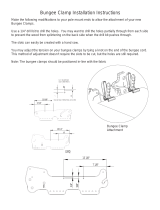
BUNGEE REPLACEMENT
REPLACEMENT BUNGEE INSTALLATION
The Visor Bungee’s can be easily replaced if they get worn or start to lose their elasticity.
1
THREAD BUNGEE THROUGH
CRIMP RECEIVER SLOT
Identify the correct Bungee Strap Clip (left or right), and thread the non-crimped end of the bungee through the
side with the Crimp Receiver Slot as shown.
2
ENGAGE BUNGEE CRIMP
Push the end of the crimp into the hole and use a
small at head screw driver to push the bungee
into place.
3
THREAD BUNGEE THROUGH
VISOR FRAME
Weave the bungee through the visor frame as shown.
The bungee should loop behind the frame.
4
THREAD BUNGEE THROUGH
BUNGEE CLEAT SLOT
Feed the bungee through the Bungee Cleat Slot as
shown.
Inside of
Visor Frame
LEFT
Crimp Receiver Slots (BOTTOM)
Bungee Cleat Slots (TOP)
RIGHT
12

BUNGEE REPLACEMENT
6
INSTALL BUNGEE WASHER
Slide the nylon washer over the end of the bungee.
5
THREAD BUNGEE THROUGH
PULL TAB OPENING
Locate the small pull tab hole and run the excess
bungee through.
7
KNOT END OF BUNGEE
Tie a knot and pull tight. Leave ¼” of the end
exposed to prevent the knot from coming lose.
8
STOW KNOT AND WASHER
INSIDE PULL TAB
Stuff the knot and washer inside the pull tab.
9
PULL TO ALIGN BUNGEE
Even out the bungee tension and repeat steps 1-9 for
the other side.
13

LENS CARE
LENS PROTECTION AND CLEANING
The Step-In Visor Lenses are coated with a hard coating on the outside to protect against scratches and light
abrasions. The inside is coated with a highly advanced anti-fog coating.
• To clean the lens use the included lens cleaning cloth to rst lightly brush away any particles.
• Then use a slightly rmer pressure to clean away any sweat or grim buildup.
• The gasket parts can be washed with mild soap and water.
14

WARRANTY
GENTEX CORPORATION LIMITED WARRANTY
Unless an individual product is covered by a separately issued warranty, Gentex warrants that all ballistic helmet shells
will be free from defects in material or workmanship under normal use and service for a period of five (5) years from
the date of delivery. Unless an individual product is covered by a separately issued warranty, Gentex warrants that
all helmet components, accessories, peripherals, and parts will be free from defects in material or workmanship under
normal use and service for a period one (1) year from the date of delivery. All repair covered by this warranty shall be
performed at Gentex’s factory, or other such warranty repair facilities of Gentex as designated by Gentex unless Gentex
specifically directs that repair services be performed at another location. Any defect corrected and found to be within
this scope of the warranty will be repaired by Gentex and all charges for labor and material will be borne by Gentex.
If it is determined that either no fault exists in Gentex, or the damage to be repaired was caused by negligence of the
user, its agents, employees or customers, you agree to pay all charges associated with each such repair. No statement,
recommendation or assistance made or offered by Gentex through its representatives to the user, its agents, employees,
or customers in connection with the purpose or intended use of any Gentex’s product shall be or constitute a waiver by
Gentex of any of the provisions of this warranty or change Gentex’s liability under this warranty.
EXCEPT WHERE PROHIBITED BY LAW, THE WARRANTY DESCRIBED ABOVE CONSTITUTES THE SOLE WARRANTY MADE
BY GENTEX EITHER EXPRESSED OR IMPLIED. THERE ARE NO OTHER WARRANTIES EXPRESSED OR IMPLIED THAT EXTEND
BEYOND THE FACE HEREOF, HEREIN, INCLUDING THE IMPLIED WARRANTIES OF MERCHANTABILITY AND FITNESS
FOR A PARTICULAR PURPOSE. IN NO EVENT SHALL GENTEX BE LIABLE FOR ANY INCIDENTAL, CONSEQUENTIAL, OR
SPECIAL DAMAGES EVEN IF ADVISED OF SUCH DAMAGES, AND THE USER, ITS AGENTS, EMPLOYEES, OR CUSTOMERS
REMEDIES SHALL BE LIMITED TO SOLELY TO THE REPAIR OR REPLACEMENT OF NONCONFORMING UNITS OR PARTS,
WHICH AMOUNT SHALL NOT EXCEED THE TOTAL PURCHASE PRICE OF THE PRODUCT UNDER WARRANTY.
Any tampering, misuse or negligence in handling or use of the product renders the warranty void. Further, the warranty
is void if, at any time, the user, its agents, employees or customers attempts to make any internal changes to any of
the components of a product; if at any time the power supplied to any part of the product exceeds the rated tolerance;
if any external device attached by the user, its agents, employees or customers creates conditions exceeding the
tolerance of the product; or if any time the serial number plate is removed or defaced. OPERATION OF THE PRODUCTS
THAT RENDERS THIS WARRANTY VOID WILL BE DEFINED TO INCLUDE ALL OF THE POSSIBILITIES DESCRIBED IN THIS
SECTION, TOGETHER WITH ANY PRACTICE THAT RESULTS IN CONDITIONS EXCEEDING THE DESIGN TOLERANCE OF
THE PRODUCTS.
15

16
/