
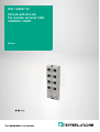
ICA-*-G60A*-IO
I/O hub with IO-Link
For module variants 16DI,
10DI6DO, 16DIO
Manual

With regard to the supply of products, the current issue of the following document is applicable: The
General Terms of Delivery for Products and Services of the Electrical Industry, published by the Central
Association of the Electrical Industry (Zentralverband Elektrotechnik und Elektroindustrie (ZVEI) e.V.)
in its most recent version as well as the supplementary clause: "Expanded reservation of proprietor-
ship"
Worldwide
Pepperl+Fuchs Group
Lilienthalstr. 200
68307 Mannheim
Germany
Phone: +49 621 776 - 0
E-mail: info@de.pepperl-fuchs.com
North American Headquarters
Pepperl+Fuchs Inc.
1600 Enterprise Parkway
Twinsburg, Ohio 44087
USA
Phone: +1 330 425-3555
E-mail: sales@us.pepperl-fuchs.com
Asia Headquarters
Pepperl+Fuchs Pte. Ltd.
P+F Building
18 Ayer Rajah Crescent
Singapore 139942
Phone: +65 6779-9091
E-mail: sales@sg.pepperl-fuchs.com
https://www.pepperl-fuchs.com

3
ICA-*-G60A*-IO
Contents
2021-01
1 Introduction................................................................................................................ 5
1.1 Content of this Document............................................................................. 5
1.2 Manufacturer .................................................................................................. 5
1.3 Target Group, Personnel ............................................................................... 5
1.4 Symbols Used ................................................................................................ 6
2 Product Description .................................................................................................. 7
2.1 Intended Use .................................................................................................. 7
2.2 System Description ....................................................................................... 7
2.3 Module Variants ............................................................................................. 8
2.3.1 ICA-16DI-G60A-IO ............................................................................................................. 8
2.3.2 ICA-16DIO-G60AL-IO......................................................................................................... 8
2.3.3 ICA-10DI6DO-G60A-IO ...................................................................................................... 8
2.4 Names and Synonyms .................................................................................. 9
2.5 Indicators........................................................................................................ 9
2.5.1 LED Indicators .................................................................................................................... 9
2.6 Interfaces and Connections ....................................................................... 10
2.6.1 X01—IO-Link interface on the I/O hub .............................................................................. 10
2.6.2 X1 – X8—Ports for the Sensors/Actuators ........................................................................ 10
2.6.3 X02—Voltage supply with M12 power (16DIO only) ......................................................... 11
2.7 Dimensions................................................................................................... 11
3 Installation................................................................................................................ 13
3.1 Mounting and Wiring ................................................................................... 13
4 Project Planning and Commissioning ................................................................... 15
5 Assigning Process Data.......................................................................................... 16
5.1 16DI Modules: ICA-16DI-G60A-IO............................................................... 16
5.1.1 Input Data ......................................................................................................................... 16
5.1.2 Output Data ...................................................................................................................... 16
5.2 10DI6DO-Module: ICA-10DI6DO-G60A-IO.................................................. 17
5.2.1 Input Data ......................................................................................................................... 17
5.2.2 Output Data ...................................................................................................................... 17
5.3 16DIO-Module: ICA-16DIO-G60AL-IO......................................................... 18
5.3.1 Input Data ......................................................................................................................... 16
5.3.2 Output Data ...................................................................................................................... 18
5.4 Description of Byte 2 and Byte 3................................................................ 19

ICA-*-G60A*-IO
Contents
4
2021-01
6 Parameterization of I/O Hub IO-Link Modules.......................................................20
6.1 IO-Link Data Storage ...................................................................................20
6.2 IO-Link Factory Setting................................................................................20
6.3 16DI module: ICA-16DI-G60A-IO.................................................................20
6.4 10DI/6DO Module: ICA-10DI6DO-G60A-IO .................................................21
6.5 16DIO module: ICA-16DIO-G60AL-IO .........................................................22
6.6 Writing the Parameter Data.........................................................................23
6.6.1 Parameter - Module Config ............................................................................................... 23
6.6.2 Parameter—Diagnosis Config........................................................................................... 23
6.6.3 Parameter—DI Config Filter .............................................................................................. 24
6.6.4 Parameter—DI Config Signal Extension ........................................................................... 25
6.6.5 Parameter—DI Config Logic ............................................................................................. 25
6.6.6 Parameter—Fail-Safe Settings.......................................................................................... 26
6.6.7 Parameter—Surveillance Timeout .................................................................................... 27
6.6.8 Parameter—Module ID ..................................................................................................... 28

ICA-*-G60A*-IO
Introduction
2021-01
5
1 Introduction
1.1 Content of this Document
This document contains information required to use the product in the relevant phases of the
product life cycle. This may include information on the following:
•Product identification
•Delivery, transport, and storage
•Mounting and installation
•Commissioning and operation
•Maintenance and repair
•Troubleshooting
•Dismounting
•Disposal
The documentation comprises the following parts:
•This document
•Datasheet
In addition, the documentation may comprise the following parts, if applicable:
•EU-type examination certificate
•EU declaration of conformity
•Attestation of conformity
•Certificates
•Control drawings
•Instruction manual
•Other documents
1.2 Manufacturer
1.3 Target Group, Personnel
Responsibility for planning, assembly, commissioning, operation, maintenance, and dismount-
ing lies with the plant operator.
Only appropriately trained and qualified personnel may carry out mounting, installation, com-
missioning, operation, maintenance, and dismounting of the product. The personnel must have
read and understood the instruction manual and the further documentation.
Prior to using the product make yourself familiar with it. Read the document carefully.
Note
For full information on the product, refer to the further documentation on the Internet at
www.pepperl-fuchs.com.
Pepperl+Fuchs Group
Lilienthalstraße 200, 68307 Mannheim, Germany
Internet: www.pepperl-fuchs.com

2021-01
6
ICA-*-G60A*-IO
Introduction
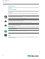
1.4 Symbols Used
This document contains symbols for the identification of warning messages and of informative
messages.
Warning Messages
You will find warning messages, whenever dangers may arise from your actions. It is mandatory
that you observe these warning messages for your personal safety and in order to avoid prop-
erty damage.
Depending on the risk level, the warning messages are displayed in descending order as fol-
lows:
Informative Symbols
Action
This symbol indicates a paragraph with instructions. You are prompted to perform an action or
a sequence of actions.
Danger!
This symbol indicates an imminent danger.
Non-observance will result in personal injury or death.
Warning!
This symbol indicates a possible fault or danger.
Non-observance may cause personal injury or serious property damage.
Caution!
This symbol indicates a possible fault.
Non-observance could interrupt the device and any connected systems and plants, or result in
their complete failure.
Note
This symbol brings important information to your attention.

ICA-*-G60A*-IO
Product Description
2021-01
7
2 Product Description
2.1 Intended Use
The devices described in this manual serve as decentralized input/output modules in a fieldbus
IO network.
We develop, manufacture, test, and document our products while observing the necessary
safety standards. If the described operating regulations and technical safety instructions for
project planning, mounting, and intended operation are observed, the products will not nor-
mally pose a danger to persons or property.
The modules meet the requirements of the EMC Directive.
The modules are designed for use in the industrial sector. The industrial environment is charac-
terized by the fact that consumers are not directly connected to the public low voltage system.
Further measures are necessary for use in private homes or in business and commercial areas.
Proper and safe operation of the product requires proper transportation, storage, installation
and mounting as well as careful operation.
A fully assembled device housing is required for the intended operation of the modules. Con-
nect the modules only to devices that meet the requirements of EN 61558-2-4 and EN 61558-
2-6.
During project planning, installation, commissioning, maintenance, and testing of devices, note
the relevant valid safety and accident prevention regulations for the specific application.
Only install cables and accessories that meet the requirements and regulations for safety, elec-
tromagnetic compatibility and, if necessary, telecommunications terminal equipment facilities,
as well as the specification stipulations. Information about which cables and accessories are
approved for installation is available from Pepperl+Fuchs or on our website.
2.2 System Description
The ICA module series has a very rugged metal housing made of die-cast zinc. The module
electronics are completely protected from environmental influences by the fully encapsulated
housing. The modules have the degrees of protection IP65, IP67, and IP69k. The permissible
temperature range of the modules is -20 °C to +70 °C. The module series is very well suited for
direct field applications in harsh industrial environments.
Despite the sturdy design, the modules have compact dimensions and low weight.
The ICA module series consists of multiple I/O hubs with IO-Link interfaces with different I/O
functionality.
•Module with 16 digital inputs (16DI)
•Module with 16 freely configurable digital inputs/outputs (16DIO)
•Module with 10 digital inputs/6 digital outputs (10DI6DO)
In principle, an ICA module with digital inputs detects binary sensor signals from the process
level and transmits them via an IO-Link master and the higher-level fieldbus system to the PLC.
ICA modules with digital outputs receive output commands from the PLC via the IO-Link mas-
ter, which they output as binary signals to connected actuators.
The modules with output functionality offer a fail-safe function. During the configuration of
these modules, the behavior of each individual output channel can be set in case of interruption
or loss of communication.
Caution!
Device interference is possible in residential areas!
This product may cause radio interference in residential areas. In this case, the owner may be
required to take appropriate countermeasures.

2021-01
8
ICA-*-G60A*-IO
Product Description
The widespread M12 connection technology is used for the electrical connection, with M12 A-
encoding for the I/O signals as well as the IO-Link interface. The 16DIO module also has a con-
nector with M12-L encoding for the voltage supply of the sensors/actuators.
2.3 Module Variants
The manual applies to subsequent module variants.
The following sections briefly describe the module variants.
2.3.1 ICA-16DI-G60A-IO
IO-Link device—I/O hub with IO-Link—16DI
The IO-Link module ICA-16DI-G60A-IO with 16 digital inputs detects binary sensor signals
from the process level and transmits them via the IO-Link master and the higher-level fieldbus
system to the PLC.
The sensors are powered by the IO-Link master supply voltage (L+) at X01. The module does
not require a separate supply voltage connection.
2.3.2 ICA-16DIO-G60AL-IO
IO-Link device—I/O hub with IO-Link—16DIO
The IO-Link module ICA-16DIO-G60AL-IO with 16 freely configurable digital inputs and outputs
detects binary sensor signals from the process level and transmits them via the IO-Link master
and the higher-level fieldbus system to the PLC. The system voltage of the IO-Link module is
supplied from the A-encoded M12 connection X01. The sensors and actuators are supplied
from the L-coded M12 power connection X02. The sensors and actuators are not galvanically
isolated from the IO-Link interface.
2.3.3 ICA-10DI6DO-G60A-IO
IO-Link device—I/O hub with IO-Link—10DI6DO
The IO-Link module ICA-10DI6DO-G60A-IO with 10 digital inputs and 6 digital outputs detects
binary sensor signals from the process level and transmits them via the IO-Link master and the
higher-level fieldbus system to the PLC. The inputs and outputs are galvanically isolated. The
sensors are powered by the IO-Link master supply voltage (L+) at X01. The actuators are sup-
plied via the advanced power supply U
Aux
(2L+) Class B of the master via X01. The module is
operated with a Class B master port and requires no separate connection of the supply voltage.
Product name Description
IO-Link and
power ports IO ports
ICA-16DI-G60A-IO IO-Link device: IO hub with IO-Link inter-
face and 16 digital inputs
IOL - M12A 8x M12
ICA-16DIO-G60AL-IO IO-Link device: IO hub with IO-Link inter-
face and 16 freely configurable digital
inputs/outputs
IOL - M12A
PWR - M12L
8x M12
ICA-10DI6DO-G60A-IO IO-Link device: IO hub with IO-Link inter-
face and with 10 digital inputs and 6 digi-
tal outputs
IOL - M12A 8x M12
Table 2.1
Caution!
Error message
The IO-Link module reports an error if power connections X1 and X2 are not both connected.

ICA-*-G60A*-IO
Product Description
2021-01
9
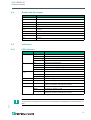
2.4 Names and Synonyms
2.5 Indicators
2.5.1 LED Indicators
Name/Synonym Description
Type A IO-Link port specification (Class A)
Type B IO-Link port specification (Class B)
I/O port X1 – X8
I/O port pin 4 (C/Q) Channel A of X1 – X8
I/O port pin 2 Channel B of X1 – X8
U
Aux
U
Auxiliary
is the auxiliary supply of the Class B IO-Link master
DI Standard digital input
DO Standard digital output
I/O Input/output
IOL IO-Link
Table 2.2
LED Color Description
IO-Link Off Module is powered down
Green Module is switched on, no communication
Green flashing Communication OK
Red Signal line overload
U
S
Off Module is powered down
Green System/sensor supply voltage OK
Red System/sensor supply voltage < 18 V
Red flashing Supply voltage overload sensor
U
Aux
Off Supply voltage not available actuator
Green Supply voltage OK actuator
Red Supply voltage < 18 V actuator
X1-X8 (A/DIA) Off Channel A—signal = 0/OFF
Orange Channel A—signal = 1/ON
Red Peripheral fault
(sensor or actuator overload/short circuit)
X1-X8 (B/DIA) Off Channel B—signal = 0/OFF
White Channel B—signal = 1/ON
Red Peripheral fault
(sensor or actuator overload/short circuit)
Table 2.3
Note
Channel errors or general errors on the IO-Link module are indicated by an illuminated red U
S
LED.

2021-01
10
ICA-*-G60A*-IO
Product Description
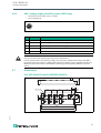
2.6 Interfaces and Connections
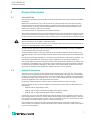
2.6.1 X01—IO-Link interface on the I/O hub
•Connection: M12 plug, 5-pin, A-coded
•Color coding: black
Figure 2.1 Schematic drawing of port X01
2.6.2 X1 – X8—Ports for the Sensors/Actuators
•Connection: M12 socket, 5 pin, A-coded
•Color coding: black
Figure 2.2 Schematic drawing of ports X1 to X8
Note
The contact arrangements described in this chapter show the front view of the plug-in area of
the connectors.
Pin 16DI (Class A) 16DIO (Class A)
10DI/6DO
(Class B) Function
1 +24 VDC (L+) +24 VDC (L+) +24 VDC (L+) System/sensor voltage (U
S
)
(from IO-Link master)
2 n.c. n.c. +24 VDC (2L+) Actuator supply (U
Aux
)
(from IO-Link master)
3 GND (L-) GND (L-) GND (L-) Reference potential for sys-
tem/sensor voltage (U
S
)
4 C/Q (IO-Link) C/Q (IO-Link) C/Q (IO-Link) IO-Link data channel
5 n.c. n.c. GND (2M) Reference potential for actua-
tor supply (U
Aux
)
Table 2.4
1
3
4
5
2
Pin 16DI 16DIO 10DI/6DO Function
1 +24 VDC (L+) +24 VDC (L+) +24 VDC (L+) Sensor supply
2 X1...X8: IN B X1...X8: IN/OUT X1...X5: IN B
X6...X8: OUT B
Digital inputs/outputs
3 GND (L-) GND (L-) GND (L-) Reference potential for sensor
supply
4 X1...X8: IN A X1...X8: IN/OUT X1...X5: IN A
X6...X8: OUT A
Digital inputs/outputs
5 FG FG FG Functional ground
Table 2.5
1
5
3
2
4

ICA-*-G60A*-IO
Product Description
2021-01
11
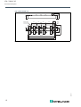
2.6.3 X02—Voltage supply with M12 power (16DIO only)
•Connection: M12 socket, 5-pin, L-coded
•Color coding: gray
Figure 2.3
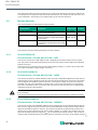
2.7 Dimensions
ICA-16DI-G60A-IO and ICA10DI6DO-G60A-IO
Figure 2.4
Pin 16DIO Function
1 24 VDC (U
S
) Sensor supply U
S
2 GND (U
L
) Reference potential for actuator supply U
L
3 GND (U
S
) Reference potential for sensor supply (U
S
)
4 24 VDC (U
L
) Actuator supply U
L
5 FG Functional ground
1
3
2
4
5
Caution!
Use of incorrect power supply units may lead to malfunctions.
For the system/sensor and actuator supply, use only power supplies that comply with PELV
(protective extra-low voltage) or SELV (safety extra-low voltage). Power supplies according to
EN 61558-2-6 (transformer) or EN 60950-1 (switching power supplies) fulfill these require-
ments.
17.6
30.7
214.5
27 27 27M12 x1 (9x)
149.3
150.8
20
30
59.6
40 11.5
16.5
158.8
M4

2021-01
12
ICA-*-G60A*-IO
Product Description
Figure 2.5
ICA-16DIO-G60AL-IO
17.6
30.7
214.5
27 27 27M12 x1 (9x)
149.3
150.8
20
30
59.6
40 11.5
16.5
158.8
M4

ICA-*-G60A*-IO
Installation
2021-01
13
3 Installation
3.1 Mounting and Wiring
General Information on Mounting and Connecting
Install the module with two M4x25/30 size screws on a level surface. The required torque is
1 Nm. For all types of mounting, use washers according to DIN 125. For the installation holes,
use a spacing of 149.3 mm to 150.8 mm.
Connect the IO-Link interface of the I/O module by means of a standardized M12 connection
line to the IO-Link master.
Due to the current limiting in accordance with IO-Link Class A, the ICA-16DI-G60A-IO module
can be connected to all ports of the ICE1-8IOL-G60L-V1D. A 3-wire line is sufficient.
The ICA-10DI6DO-G60A-IO module must be connected to a Class B port. To connect the aux-
iliary power supply UAux, use a 5-wire line.
The ICA-16DIO-G60AL-IO module has an additional voltage supply via X02. Using a suitable
M12 connection line, connect the M12 connector to the DC power supply provided.
For the intended use of an IO-Link device—I/O hub, connection to an IO-Link master is essen-
tial!
Note
To dissipate interference currents and for the EMC strength, the modules use a short circuit to
ground with an M4 thread. This is marked with the symbol for grounding and the label "XE."
Note
Connect the module using an electrical connection with low impedance to the reference
ground. In the case of a grounded mounting surface, you can connect the module directly via
the fixing screws.
Note
For non-grounded mounting surfaces, use a ground strap or a suitable FE conductor. Connect
the ground strap or FE conductor to the grounding point using an M4 screw and place a washer
and a serrated washer under the fixing screw if possible.
Note
FOR UL APPLICATION
Connect devices using only a UL-certified cable with suitable ratings (CYJV or PVVA.) To
program the controller, please consult the manufacturer information and use only the
appropriate accessories.
Note
FOR UL APPLICATION
Installation and operation of the modules is permitted for indoor use only. Please note the
maximum mounting and operating altitude of 2000 m above sea level. Permitted up to a
maximum pollution degree of 2.
Warning!
Risk of burning
Terminals, the enclosure of field-wired terminal boxes or components may exceed tempera-
tures of 60 °C. This presents a risk of burning.

2021-01
14
ICA-*-G60A*-IO
Installation
Warning!
Risk of damage
Any work on the electrical wiring of the modules may only be carried out in a de-energized state
to prevent the destruction of electronic components.

ICA-*-G60A*-IO
Project Planning and Commissioning
2021-01
15
4 Project Planning and Commissioning
The I/O hubs with IO-Link are operated with an IO-Link master with version 1.1. The IO-Link
masters from Pepperl+Fuchs support standard 1.1.
The data storage mechanism is supported only in connection with an IO-Link master function
with standard 1.1.
More information on project planning and commissioning is available in the respective fieldbus
protocol-specific IO-Link master documentation.

2021-01
16
ICA-*-G60A*-IO
Assigning Process Data
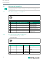
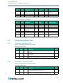
5 Assigning Process Data
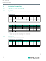
5.1 16DI Modules: ICA-16DI-G60A-IO
5.1.1 Input Data
This module provides a total of four bytes of input data, the input process image is mapped in
the first two bytes as follows:
Standard mapping
Alternative Mapping
Legend
•X1-A…X8-A: input status channel A (pin 4) for slots X1 to X8
•X1-B…X8-B: input status channel B (pin 2) for slots X1 to X8
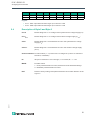
5.1.2 Output Data
This module provides four bytes of output data.
Standard Mapping / Alternative Mapping
INPUT Bit 7 Bit 6 Bit 5 Bit 4 Bit 3 Bit 2 Bit 1 Bit 0
Byte 0 X4-B X4-A X3-B X3-A X2-B X2-A X1-B X1-A
Byte 1 X8-B X8-A X7-B X7-A X6-B X6-A X5-B X5-A
Byte 2 Channel Number OVL
U
Aux
OVL U
S
UV
Aux
UV
S
Byte 3 MODE ID
Table 5.1
INPUT Bit 7 Bit 6 Bit 5 Bit 4 Bit 3 Bit 2 Bit 1 Bit 0
Byte 0 X8-A X7-A X6-A X5-A X4-A X3-A X2-A X1-A
Byte 1 X8-B X7-B X6-B X5-B X4-B X3-B X2-B X1-B
Byte 2 Channel Number OVL
U
Aux
OVL U
S
UV
Aux
UV
S
Byte 3 MODE ID
INPUT Bit 7 Bit 6 Bit 5 Bit 4 Bit 3 Bit 2 Bit 1 Bit 0
Byte 0 ––––––––
Byte 1 ––––––––
Byte 2 ––––––––
Byte 3 RST –––––––
Table 5.2

ICA-*-G60A*-IO
Assigning Process Data
2021-01
17
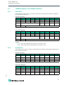
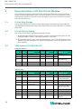
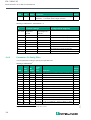
5.2 10DI6DO-Module: ICA-10DI6DO-G60A-IO
5.2.1 Input Data
This module provides a total of four bytes of input data, the input process image is mapped in
the first two bytes as follows:
Standard mapping
Alternative Mapping
Legend
•X1-A…X5-A: input status channel A (pin 4) for slots X1 to X5
•X1-B…X5-B: input status channel B (pin 2) for slots X1 to X5
5.2.2 Output Data
This module also provides four bytes of output data, the output process image is mapped in the
first two bytes as follows:
Standard mapping
Alternative Mapping
INPUT Bit 7 Bit 6 Bit 5 Bit 4 Bit 3 Bit 2 Bit 1 Bit 0
Byte 0 X4-B X4-A X3-B X3-A X2-B X2-A X1-B X1-A
Byte 1 ––––––X5-B X5-A
Byte 2 Channel Number OVL
U
Aux
OVL U
S
UV
Aux
UV
S
Byte 3 MODE ID
Table 5.3
INPUT Bit 7 Bit 6 Bit 5 Bit 4 Bit 3 Bit 2 Bit 1 Bit 0
Byte 0 –––X5-A X4-A X3-A X2-A X1-A
Byte 1 –––X5-B X4-B X3-B X2-B X1-B
Byte 2 Channel Number OVL
U
Aux
OVL U
S
UV
Aux
UV
S
Byte 3 MODE ID
INPUT Bit 7 Bit 6 Bit 5 Bit 4 Bit 3 Bit 2 Bit 1 Bit 0
Byte 0 ––––––––
Byte 1 X8-B X8-A X7-B X7-A X6-B X6-A – –
Byte 2 ––––––––
Byte 3 RST –––––––
Table 5.4
INPUT Bit 7 Bit 6 Bit 5 Bit 4 Bit 3 Bit 2 Bit 1 Bit 0
Byte 0 X8-A X7-B X6-B –––––
Byte 1 X8-B X7-B X6-B –––––
Byte 2 ––––––––
Byte 3 RST –––––––
Table 5.5

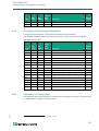
2021-01
18
ICA-*-G60A*-IO
Assigning Process Data
Legend
•X6-A…X8-A: input status channel A (pin 4) for slots X6 to X8
•X6-B…X8-B: input status channel B (pin 2) for slots X6 to X8
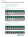
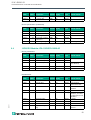
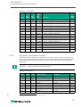
5.3 16DIO-Module: ICA-16DIO-G60AL-IO
5.3.1 Input Data
This module provides a total of four bytes of input data, the input process image is mapped in
the first two bytes as follows:
Standard mapping
Alternative Mapping
Legend
•X1-A…X8-A: input status channel A (pin 4) for slots X1 to X8
•X1-B…X8-B: input status channel B (pin 2) for slots X1 to X8
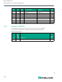
5.3.2 Output Data
This module also provides four bytes of input data, the output process image is mapped in the
first two bytes as follows:
Standard mapping
Alternative Mapping
INPUT Bit 7 Bit 6 Bit 5 Bit 4 Bit 3 Bit 2 Bit 1 Bit 0
Byte 0 X4-B X4-A X3-B X3-A X2-B X2-A X1-B X1-A
Byte 1 X8-B X8-A X7-B X7-A X6-B X6-A X5-B X5-A
Byte 2 Channel Number OVL
U
Aux
OVL U
S
UV
Aux
UV
S
Byte 3 MODE ID
Table 5.6
INPUT Bit 7 Bit 6 Bit 5 Bit 4 Bit 3 Bit 2 Bit 1 Bit 0
Byte 0 X8-A X7-A X6-A X5-A X4-A X3-A X2-A X1-A
Byte 1 X8-B X7-B X6-B X5-B X4-B X3-B X2-B X1-B
Byte 2 Channel Number OVL
U
Aux
OVL U
S
UV
Aux
UV
S
Byte 3 MODE ID
INPUT Bit 7 Bit 6 Bit 5 Bit 4 Bit 3 Bit 2 Bit 1 Bit 0
Byte 0 X4-B X4-A X3-B X3-A X2-B X2-A X1-B X1-A
Byte 1 X8-B X8-A X7-B X7-A X6-B X6-A X5-B X5-A
Byte 2 ––––––––
Byte 3 RST –––––––
Table 5.7
INPUT Bit 7 Bit 6 Bit 5 Bit 4 Bit 3 Bit 2 Bit 1 Bit 0
Byte 0 X8-A X7-A X6-A X6-A X4-A X3-A X2-A X1-A
Byte 1 X8-B X7-B X6-B X5-B X4-B X3-B X2-B X1-B

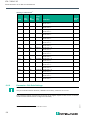
ICA-*-G60A*-IO
Assigning Process Data
2021-01
19
Legend
•X1-A…X8-A: input status channel A (pin 4) for slots X1 to X8
•X1-B…X8-B: input status channel B (pin 2) for slots X1 to X8
5.4 Description of Byte 2 and Byte 3
Byte 2 ––––––––
Byte 3 RST –––––––
INPUT Bit 7 Bit 6 Bit 5 Bit 4 Bit 3 Bit 2 Bit 1 Bit 0
UV U
S
Module diagnosis—Low voltage of the system/sensor voltage supply (U
S
)
UV U
Aux
Module diagnosis—Low voltage of the actuator voltage supply (U
Aux
)
OVL
S
Module diagnosis—Overload/short circuit in the system/sensor voltage
supply (U
S
)
OVL
Aux
Module diagnosis—Overload/short circuit in the actuator voltage supply
(U
Aux
)
Channel Number Port information (1 – 8) of the OVL U
Aux
diagnosis (or OVL U
S
channel in-
formation, if available)
ID ID byte for detection of a tool change, 0 = not used, ID = 1 – 127
MODE Possible values
1 = User parameterization is active, different from the standard settings
0 = Standard parameterization is active
RST Reset to factory setting of the parameterization 50 ms after detection of the
signal "1"

2021-01
20
ICA-*-G60A*-IO
Parameterization of I/O Hub IO-Link Modules
6 Parameterization of I/O Hub IO-Link Modules
The parameters set during system start-up are transferred to the device. The device and the
master store these parameters. In case of a module replacement, the saved parameters can be
automatically transferred to the new module. The behavior of the master and device is defined
at the IO-Link master port.
6.1 IO-Link Data Storage
The I/O hubs with IO-Link and the IO-Link masters support the data storage functionality. All
user-adjustable parameters are saved in the module and in the master. (Exception: ID number
index 0x60)
6.2 IO-Link Factory Setting
The module can be reset to the factory settings in two ways.
1. By activating the "Restore Factory Settings" system command specified by IO-Link. The
command must be written to index 0x02, subindex 0, with 0x82.
2. By setting the output bit "RST" in the process data, byte 3, bit 7. The prerequisite for this is
that the command in the parameter—Module Configuration, Index 0x40, subindex 3, has
been activated.
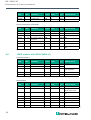
6.3 16DI module: ICA-16DI-G60A-IO
Direct parameter 1
Identification
Index
Sub-
Index Parameter Access
Data length
[byte]
Data
type Default values
0x0000 8 Vendor ID1 (MSB) R 1 UINT8 0x0001
0x0000 9 Vendor ID2 (MSB) R 1 UINT8
0x0000 10 Device ID1 (MSB) R 1 UINT8 0x0F0201
(dec 983553)
0x0000 11 Device ID2 R 1 UINT8
0x0000 12 Device ID3 (LSB) R 1 UINT8
Table 6.1
Index
Sub-
Index Parameter Access
Data length
[byte]
Data
type Default values
0x0010 0 Vendor name R 64 String Pepperl+Fuchs
0x0011 0 Vendor text R 64 String www.pepperl-
fuchs.com/io-link
0x0012 0 Product name R 64 String ICA-16DI-G60A-IO
0x0013 0 Product ID R 64 String 313335
0x0014 0 Product text R 64 String ICA-16DI-G60A-IO,
A-coded, IO-Hub
with IO-Link, 16DI
0x0015 0 Serial number R 16 String P+F SN
0x0016 0 Hardware revision R 64 String HW01.00
0x0017 0 Firmware revision R 64 String FW01.00
0x0018 0 Application specific
tag
R/W 32 String Your automation, our
passion.
Page is loading ...
Page is loading ...
Page is loading ...
Page is loading ...
Page is loading ...
Page is loading ...
Page is loading ...
Page is loading ...
Page is loading ...
-
 1
1
-
 2
2
-
 3
3
-
 4
4
-
 5
5
-
 6
6
-
 7
7
-
 8
8
-
 9
9
-
 10
10
-
 11
11
-
 12
12
-
 13
13
-
 14
14
-
 15
15
-
 16
16
-
 17
17
-
 18
18
-
 19
19
-
 20
20
-
 21
21
-
 22
22
-
 23
23
-
 24
24
-
 25
25
-
 26
26
-
 27
27
-
 28
28
-
 29
29


Pepperl+Fuchs ICA-16DI-G60A-IO Owner's manual
- Type
- Owner's manual
- This manual is also suitable for
Ask a question and I''ll find the answer in the document
Finding information in a document is now easier with AI
Related papers
-
Pepperl+Fuchs ICE11-8IOL-G60L-V1D Owner's manual
-
-
-
-
-
-
-
-
-
Other documents
-
Hirschmann EtherCAT Digital-I/O User manual
-
Seneca R-16DI-8DO Installation guide
-
WAGO 16-Channel Digital Input/Output User manual
-
-
-
 Kromschroder UVS 10 Operating instructions
-
Eaton XN-312-GW-CAN User manual
-
-
Weidmuller UR67-MP-HP-8DIDO-12-60M User manual
-
