LM3 Series
Saltwater Chlorinator
Installation Guide
and Owner’s Manual

2
READ AND FOLLOW ALL INSTRUCTIONS.
ELECTRICAL HAZARD
• To reduce risk of electrical shock
-
Make sure all power to pool equipment area is off prior to any installation or removal of Clearwater components.
- Replace damaged power pack cord immediately.
- Do not bury cord. Locate cord to minimize abuse from lawn mowers, hedge trimmers and other equipment.
• Severe shock or injury will likely occur as a result of a drill or drill cord coming in contact with water.Never allow electric drill or cord to come
in contact with water. Only plug drill into a Class A (5 Milliampere Trip) protected Ground Fault Circuit Interrupter (GFCI) in accordance with
the National Electrical Code Section 680 (USA only). Please see your drill owner’s manual for further safety precautions.
• Install the power pack at least 10 feet from the inside walls of a pool to prevent any possibility of the unit coming in contact with water.
• Your Clearwater Chlorinator has been designed with an electronic flow switch.This device automatically switches the chlorinator ‘OFF’when
the water through the cell stops.To prevent cell damage and personal injury, do not in any way interfere with this system which has been
designed for your protection.
CHEMICAL USE HAZARD
• To avoid personal injury when working with pool chemicals, always wear rubber gloves and eye protection and work in a well-ventilated area.
Use caution when choosing a location to open and use chemicals as the
y may damage any surface in which they come in contact.
• The addition of certain chemicals can reduce the effectiveness of chlorine.Always make sure that proper residual chlorine levels are
maintained to avoid personal injury.
• This product manufactures chlorine.Individuals with any type of chlorine sensitivity should take the appropriate precautions to avoid
injury or illness.
EQUIPMENT
WATER PRESSURE HAZARD
• Always turn pump off prior to installing or removing any Clearwater cell. Your pump/filter system is operated under pressure and the pressure
m
ust be released before you begin work. Please see your pump/filter owner’s manual for further instructions.
• To avoid cell damage, water pressure in the cell must not exceed 40 psi (276 kPa)
PREVENT CHILD INJURY AND DROWNING
• T
o reduce the risk of injury, do not permit children to operate this product.
• Do not let anyone, especially small children, sit, step, lean, or climb on any equipment installed as part of your pool’s operational system.
Unless otherwise stated, ALL components of your pool's operational system should be located at least 3 feet from the pool so children
cannot use the equipment to gain access and be injured or drown.
IMPORTANT SAFETY INSTRUCTIONS
• Chlorinator must be installed and operated as specified.
• Scratching or bending plates in cell housing can reduce cell life.
• Power to the LM3 should be turned off before unplugging the cell connectors to prevent cell damage and low voltage sparks.
• Keep the cell terminals protected with a light coating of silicone grease to allow for a positive electric connection.Use of any other type of
grease may damage the terminal seals and o-rings. Do not immerse these terminals in acid wash solution, and avoid accidental contact with
salt water.
• Water above the temperature of 104 degrees F (40 degrees C) flowing through the cell can cause plastic cell to discolor.
• Power pack must not be installed directly above any other heat source such as filter, pump or heater. It must be at least 1 ft. (300 mm) from
the ground to allow free circulation of air around it. It must not be installed in a closed box. If the power pack is to be installed on a post, then
it must be centrally positioned on a flat panel of suitable waterproof material at least 10 inches (240mm) wide and 18 inches (440mm) high.
• Check the cell frequently to prevent the accumulation of pool debris that for any reason may have by-passed the pool filter.
SAVE ALL INSTRUCTIONS.
CAUTION
Failure to heed the following warnings could cause damage to pool equipment
or personal injury.
!
WARNING
Failure to heed the following warnings can result in permanent injury,
electrocution or drowning.
!

3
Safety Instructions . . . . . . . . . . . . . . . . . . . . . . . . . . . . . . . . . . . . . . . . . . . . . . . . . . . . . . .2
How the Clearwater Chlorinator Works . . . . . . . . . . . . . . . . . . . . . . . . . . . . . . . . . . . . . . .4
LM3 Product Specifications . . . . . . . . . . . . . . . . . . . . . . . . . . . . . . . . . . . . . . . . . . . . . . . .4
Installation . . . . . . . . . . . . . . . . . . . . . . . . . . . . . . . . . . . . . . . . . . . . . . . . . . . . . . . . . . . . .5
Plumbing the Cell . . . . . . . . . . . . . . . . . . . . . . . . . . . . . . . . . . . . . . . . . . . . . . . . . . . .5
Flooded Plumbing Installation . . . . . . . . . . . . . . . . . . . . . . . . . . . . . . . . . . . . . . . .5
By-pass Plumbing Installation . . . . . . . . . . . . . . . . . . . . . . . . . . . . . . . . . . . . . . . .5
Multiple Installations . . . . . . . . . . . . . . . . . . . . . . . . . . . . . . . . . . . . . . . . . . . . . . .5
Installing the Power Pack . . . . . . . . . . . . . . . . . . . . . . . . . . . . . . . . . . . . . . . . . . . . . . .6
Wiring to a Controller . . . . . . . . . . . . . . . . . . . . . . . . . . . . . . . . . . . . . . . . . . . . . . . . . .6
Connecting the Communication Cable . . . . . . . . . . . . . . . . . . . . . . . . . . . . . . . . .7
Interface for Automation System Controller . . . . . . . . . . . . . . . . . . . . . . . . . . . . .8
Check Salt / No Flow Warnings to Controllers . . . . . . . . . . . . . . . . . . . . . . . . . . .8
Operation . . . . . . . . . . . . . . . . . . . . . . . . . . . . . . . . . . . . . . . . . . . . . . . . . . . . . . . . . . . . . .9
Control Panel Functions . . . . . . . . . . . . . . . . . . . . . . . . . . . . . . . . . . . . . . . . . . . . . . .9
Control Panel Indicator Lights . . . . . . . . . . . . . . . . . . . . . . . . . . . . . . . . . . . . . . . . . .10
Startup . . . . . . . . . . . . . . . . . . . . . . . . . . . . . . . . . . . . . . . . . . . . . . . . . . . . . . . . . . . .10
Operating Tips . . . . . . . . . . . . . . . . . . . . . . . . . . . . . . . . . . . . . . . . . . . . . . . . . . . . . .10
Maintenance . . . . . . . . . . . . . . . . . . . . . . . . . . . . . . . . . . . . . . . . . . . . . . . . . . . . . . . . . .12
Regular Maintenance Checks . . . . . . . . . . . . . . . . . . . . . . . . . . . . . . . . . . . . . . . . . .12
Tips On Water Chemistry . . . . . . . . . . . . . . . . . . . . . . . . . . . . . . . . . . . . . . . . . . . . .12
Adding Salt to the Pool . . . . . . . . . . . . . . . . . . . . . . . . . . . . . . . . . . . . . . . . . . . . . . .13
Salt Requirements Chart . . . . . . . . . . . . . . . . . . . . . . . . . . . . . . . . . . . . . . . . . . .14
Adding Stabilizer to the Pool . . . . . . . . . . . . . . . . . . . . . . . . . . . . . . . . . . . . . . . . . . .15
Stabilizer Requirements Chart . . . . . . . . . . . . . . . . . . . . . . . . . . . . . . . . . . . . . .15
Manually Cleaning the Cell . . . . . . . . . . . . . . . . . . . . . . . . . . . . . . . . . . . . . . . . . . . .15
Resetting the Fuse . . . . . . . . . . . . . . . . . . . . . . . . . . . . . . . . . . . . . . . . . . . . . . . . . .16
Preventing Damage Caused by Insects . . . . . . . . . . . . . . . . . . . . . . . . . . . . . . . . . .16
Troubleshooting . . . . . . . . . . . . . . . . . . . . . . . . . . . . . . . . . . . . . . . . . . . . . . . . . . . . . . . .17
Clearwater LM3 Series Limited Warranty . . . . . . . . . . . . . . . . . . . . . . . . . . . . . . . . . . . . .19
Table of Contents

Congratulations on the purchase of your new Clearwater Chlorinator. Please take a few moments to
read through the entire manual before installing or using your new unit.Your chlorinator must be installed
and operated as specified.
How the Clearwater Chlorinator Works
Common salt (sodium chloride) is made up of two elements, sodium and chloride.When the Clearwater
LM3 is installed, a measured quantity of salt is dissolved in the pool water to create a mild saline solution.
As part of the daily filtration cycle, pool water is passed through the Clearwater electrolysis cell to
produce chlorine which is dissolved instantly into the water. The Clearwater LM3 also produces ozone in
the cell as a by-product.
The chlorine instantly starts to destroy bacteria, viruses and algae, and in doing so reverts to dissolved
salt.This cycle continues with more new chlorine being produced from the salt water in the electrolysis
cell, sanitizing the pool and changing once more back to dissolved salt.
Everyday, when the LM3 and filtration system are switched on, dust and debris are trapped by the filter
and the Clearwater sanitizes the water to make it safe and sparkling clean.
Important:To ensure the LM3 works at maximum efficiency, regularly check and maintain the
c
hemistry of your pool.
Water Chemistry Requirements
LM3 Product Specifications
The Clearwater LM3 Series chlorinator should be installed on residential pools only. Zodiac Pool Care,
Inc. does not recommend installing a salt water chlorinator on a pool using a stainless steel filter.
Salt level in the Clearwater pool should never exceed 13,000 ppm. Salt levels above 6,000 ppm may void
other equipment warranties and damage other components or metal items of your pool equipment.
4
Salt Concentration 4,000 ppm
pH 7.2 to 7.6
Chlorine Stabilizer
(Cyanuric Acid) 40 to 100 ppm
depending on regional climate
Total Alkalinity 80 to 120 ppm
Total Calcium Hardness 200 to 400 ppm
Free Chlorine 1 to 3 ppm
Salt Level Requirement: 4000 ppm
Max Salt Level: 13,000 ppm
Max Chlorine Output/Hour
(Gas Chlorine Equivalent)
LM3-15: 15 grams/hour
LM3-24:
24 grams/hour
LM3-40: 40 grams/hour
Power Requirements: 220 volt, 3 Amp draw
Plumbing: 1 1/2" or 2" Sch 40 PVC
Min Flow Rate: 20 gallons/minute
Max Operating Pressure: 40 psi
Max Water Temp Through Cell: 104° F
Dimensions:
Cell 15 1/2" x 5 3/4" x 6 1/2"
P
ower Pack 7 5/8" x 14 3/4" x 4 7/8"

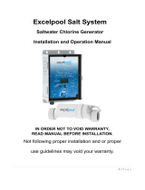
Clearwater saltwater chlorinators must be installed by a qualified swimming pool professional or
certified electrician. If you need assistance in finding a qualified installer, please contact Customer
Service at 1-800-822-7933.
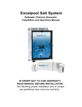
Plumbing the Cell
The Clearwater cell MUST be installed horizontally, with the ports down, as the last piece of pool
equipment on the line. The cell design forms a natural gas trap. Even though the LM unit has an internal
flow sensor, this installation provides a secondary safety feature to prevent gas build-up within the system.
• The inlet and outlet ports are labeled on the cell.
• There are no height restrictions or requirements.
•
Install cell close to power pack to accommodate the lenght of the output cable.
• The ports are 2" and require sch 40 rigid PVC only.1 1/2" PVC bushings are provided. Any standard
PVC cement may be used. Allow adequate drying time before turning on the chlorinator.
Important Note: If pressure must be applied
to the top of the shroud (cell), apply with hands
on either end ONL
Y.
Flooded Plumbing Installation
This occurs when the water level of the pool is above the height of the pool equipment. Some pool
systems have valves installed to isolate the equipment. If not, install a ball valve on the inlet side of the
cell and a one-way check valve on the outlet side of the cell.This will eliminate the possibility of having a
gas build-up and possible cell damage, and allow the cell to be removed for cleaning if needed.
By-pass Plumbing Installation
If the cell is plumbed on by-pass, a control valve should be installed on the inlet side of the cell.
Multiple Installations
If conditions require multiple installations, the LM3 can be plumbed in either series or parallel (preferred
method) as long as the header/manifold is balanced, providing equal flow to each chlorinator.
5
Installation
Salt Cell &
Electrode
Power Pack
Inlet
Outlet
Pool
Pump
Filter
Heater

6
Installing the Power Pack
The power pack can be mounted on a wall or a post. If mounting on a post, center the Power Pack on a
flat panel of waterproof material at least 10" W x 18" H.If mounting on a wall, it can be secured by the
chassis (preferred method) or hang by cover.
• Do not enclose the power pack in any box.
• Do not install it above any heat source.
• Install it a minimum of 10 feet from the pool edge. Refer to local building codes for requirements.
• The power pack is hard-wired to 220V ONLY.Wire it to the "LOAD" side of the pump timer, so
that the c
hlorinator is powered only when the pump is powered.
• The 3 ft input cable cannot be removed. (Removal will void ETL approval.) Use of a junction box
ma
y be required in some installations.
• Attach the yellow plug cap to the cell and replace the blue cap.
Wiring to an Automation System Controller
The LM3 Saltwater Chlorinator can run independently or be connected to a Pool Automation System.Two
connection methods are available.
Via an Auxiliary Relay at the Controller
(For installations using non-compatible controllers.)
Using this method the LM3 main power is connected to an auxiliary relay in the pool automation system
controller.The LM3 unit is switched on and off as determined by the controller.
The “Output Setting” and the selection of “Super Chlorinate” must be selected at the LM3 control panel.
The LM3 will retain these settings when switched on by the controller until they are manually changed.
The Super Chlorinate function will remain active for a total of 24 operating hours after
being selected.
IMPOR
TANT:The LM3 should only have power when there is water flow and actuator valves
should never block the flow when power is on. Refer to the controller’s installation guide for
additional information.
Via a Communications Link
The LM3 has the capability of being interfaced with a number of controller units:
• Polaris EOS
• Jandy Aqualink RS* (REV K and L)
• Pentair IntelliTouch**
Using this method, main power is supplied to the LM3 via the controller’s PUMP output and a
communications link is made between the LM3 and the Pool Automation system.
Hardwire the LM3 power pack to the LOAD side of the pool pump relay.While wiring to the pump relay is
the preferred method, the LM3 main power can be wired to an auxiliary relay.
*Jandy Aqualink RS is a Registered Trademark of Water Pik Technologies, Inc.
**Pentair IntelliTouch is a Registered Trademark of Pentair Pool Products

7
When the communication link is connected, the pool automation system becomes the master control for
the LM3 enabling the pool owner to control all settings of the LM3 via the controller panel.Warning
messages for check salt and no flow will be displayed at the controller panel.The lights on the LM3 will
illuminate but the buttons will not function.
When the communication link is removed, control of LM3 settings returns to the LM3 control panel.
NOTE: After a change is made at the controller, it may take several seconds for the change to be
reflected on the LM3 fr
ont panel, this delay depends on the controller being used.
Connecting the Communication Cable
1. Remove the LM3 Power Pack cover and connect the 4-conductor communication wire to the “eos
com” terminal block on the LM3 control PCB, mounted in the LM3 cover.The wiring configurations
for the various controllers are as shown below:
Polaris Eos Jandy Aqualink RS Pentair IntelliTouch
Note: The wiring configurations are the same for both Jandy Rev K and
Rev L controllers.
Note: When connecting to the Jandy Aqualink RS controller with Rev L, the LM3
will appear in the settings menu as an "AquaPure" chlor
inator.
2. Fit the communication wire into
the slot beside the cell output
cable cord grip.
3. Secure the wire to the output
cable in two places with cable
ties, cutting any excess off
the ties.
Since the LM3 chlorinator can be
connected to several different
controllers, it is necessary to select
and setup an interface for the specific
unit controlling the LM3.
LM3 Control PCB
Communication Terminal Block
Red
GreenYel/White
Black
Black = Signal+ (A)
Yel/White = Signal- (B)
Green = 0V
Red = V+
Black = Signal+ (A)
Yel/White = Signal- (B)
Green = 0V
Red = V+
LM3 Control PCB
Communication Terminal Block
Red
BlackGreen
Yel/White
Black = 0V
Yel/White = Signal+ (A)
Green = Signal- (B)
Red = V+
LM3 Control PCB
Communication Terminal Block
Red
GreenYel/White
Black
Cable Tie
2 Places
Slot Beside
Cord Grip
Communications
Cable

8
Interface for Automation System Controllers
1. Turn on power to the LM3 and pump via the controller.
2.
Press the SERVICE button (hidden above the “3” in LM3)
down for at least 20 seconds while observing the green
SUPER CHLORINATE light.The LED will flash
momentarily, either 1, 2 or 3 times, then go out for
approximately 5 seconds.
3. Continue to hold down the SERVICE button until the correct
number of flashes for the controller being used is observed.
Then release the button.
Controller: # of Flashes: Off Time:
POLARIS Eos 1 Approximately 5 seconds
PENTAIR IntelliTouch 1 Approximately 5 seconds
JANDY AquaLink RS (rev K) 2 Approximately 5 seconds
JANDY AquaLink RS (rev L) 3 Approximately 5 seconds
A software connection should have been made.To verify a valid connection, observe the menu screen of
the controller being used. If the chlorinator does not appear to have made a connection, try resetting both
the LM3 and the controller.
When connected to one of these controllers the LM3 behaves as a “drone”, responding only to the
controller, so none of the buttons on the LM3 will function.
If the communication link between the controller and the LM3 is lost, the LM3 will continue operation as it
was before the controller lost connection. It will behave as a “stand alone” unit until the controller is
reconnected or the user changes the settings.
Check Salt / No Flow Warnings to Controllers
When a low salt or no flow condition occurs, the LM3 sends a message to the controller and the controller
signals the user to check for the condition as indicated below.
LM3 Display Panel
Hidden
Service
Button
Low Salt
The CHECK SALT indicator light on the LM3
power pac
k is illuminated:
Polaris Eos: flashes the error code "‘Check
Chlor
inator" on the screen, and
displays a salt level of 2900 ppm..
Jandy Aqualink RS (REV K):displays a salt
le
vel of 2900 ppm.
Jandy Aqualink RS (REV L): displays a salt
le
vel of 2900 ppm, as well as a LOW SALT
warning message.
Pentair IntelliTouch: displays a salt level of
2900 ppm and a LOW SALT warning message
Alw
ays test the salt level in the pool before adding
salt as water temperature or scaling of the cell can
cause the CHECK SALT light to illuminate.
No Flow
The red NO FLOW indicator light on the LM3
will illuminate:
Polaris Eos: flashes “Check Chlorinator”
and displa
ys a 0 ppm salt level.
Jandy Aqualink RS (REV K):displays a
salt level of 0 ppm.
Jandy Aqualink RS (REV L):displays
“No Flo
w”
Pentair IntelliT
ouch: displays “Check
Flow/PCB”

9
Operation
The chlorine production of the Clearwater LM3 is controlled by the number of hours the LM3 and filtration
system are ON, and the chlorine output setting. Power to the unit must be controlled by the pump timer.
Chlorinator functions can only be set when the filtration system is running.
The Clearwater LM3 includes a Super Chlorinate feature which automatically super chlorinates the pool
for an approximated 24-hour period of pool pump operation.The unit is fitted with indicator lights that
reflect the operation of the chlorinator, the concentration of salt in the pool, and the water flow.
The LM3 uses reverse polarity technology to minimize scaling on the cell.The LM3 also includes an
electronic flow sensor that automatically switches the chlorinator OFF when water through the cell stops.
To prevent cell damage and personal injury, do not in any way interfere with this system as it has
been designed for your protection.
Control Panel Functions
ON / OFF Button
This button switches the LM3 ON and OFF. One yellow or a series of green lights appear in the chlorine
output indicator window when the unit is ON.
OUTPUT Button
This button is used to set the chlorine output.To set, press the button repeatedly until maximum is
reached on the chlorine output indicator.
An extra push of the button will reset the output to minimum.
SUPER CHLORINATE Button
Use the Super Chlorinate function to rapidly add chlorine to the pool. Pressing automatically super
chlor
inates the pool for approximately 24 hours of pool pump run time.
LM3 Display Panel
Chlorine
Output
Indicator
Super
Chlor
inate
Indicator
Check Salt
Indicator
No Flow
Indicator
Output
Adjustment
Super Chlorinate
Function Switch
ON/OFF

10
Control Panel Indicator Lights
Chlorine Output
A series of six lights indicates the chlorine output setting of the LM3 – more lights equals greater chlorine
production.The light does not show the actual chlorine reading in the pool. Use of a test kit is required to
confirm the Free Chlorine reading of the pool water. Note:The output lights will not increase if the salt
level is too low (below 2900ppm) and/or the water is too cold (below 65˚).
The yellow power light flashes for a few minutes when reversing polarity to self clean, indicating no
output dur
ing this time.The unit reverts back to its previous output setting when cleaning is complete.
Super Chlorinate
This light indicates that the Super Chlorinate feature has been selected.It will turn OFF when the Super
Chlorinate period has ended.
Check Salt
The Check Salt light will come on at any salt level between 3000 ppm and 4000 ppm depending on mains
voltage, water temperature (below 65˚) & the salt level.This is not a fault but a precaution to ensure the
salt level is never too low.The Check Salt light may also come on if the cell is scaled, indicating manual
cleaning is required.When the light is on, the chlorine output light may not reach maximum.Once the low
salt condition is corrected, the output will function again. Note: Operating the LM3 at reduced salt levels
may shorten the life of the cell.
No Flow
If light is ON, it indicates no water flow in the cell.The chlorine output will also turn off in this instance.
Startup
Before starting the LM3 system the required amount of salt (based on pool size) must be added to the
pool. (See Salt Requirements chart in Maintenance). Note: On new plaster pools, wait 4 weeks before
adding salt. During this period, unplug the chlorinator output cable and manually chlorinate the pool.
When switched on for the first time, the chlorinator goes through an initialization sequence, indicated by
the amber LED being illuminated. After a short period the LED will switch off and the chlorinator will begin
normal operation.
The chlorinator defaults to the ‘zero output’state.The user can then select the desired output level.Start
the operation of the LM3 at maxim
um output.
The micro-processor in the LM3 retains the chlorine output and super chlorinate settings, and the polarity
reversal time in memory when the unit is turned off, unless the setting was changed less than one minute
before turning off.
Operating Tips
• Run the filtration and chlorination system for at least 6 to 8 hrs per day.
During very hot weather it may be necessary to run the system for additional hours. In winter, where
pools remain open, r
un the filtration system for about 4 hours per day.Shorter periods will help
lengthen the life of the cell electrodes.

11
• Maintain the free chlorine residual in the pool at 1 - 3 ppm.
Increasing the daily operating period of the system increases the free chlorine reading, and a shorter
oper
ating period reduces the chlorine reading. Likewise, operating the chlorinator at maximum output
will produce a higher chlorine reading than operating the chlorinator at a lower setting.
• Maintain chlorine stabilizer (cyanuric acid) level between 40-100 ppm.
Specific requirements will vary depending on your regional climate. Chlorine stabilizer helps to keep a
satisf
actory free chlorine reading in hot sunny climates.Extremely hot and sunny climates will require
readings at the higher end of the range.Refer to Stabilizer Requirements chart in Maintenance.
• It is absolutely essential that the pH of the pool be maintained in the range of 7.2 - 7.6.
Regularly test or have a pool professional test the pH level in the pool.The effectiveness of chlorine
as a sanitiz
er is significantly reduced as the pH rises. At a pH of 8.0, nearly all of the chlorine being
added to the pool is wasted, and it is almost impossible to maintain a satisfactory free chlorine
reading. Additionally, pH readings at 8.0 and higher increase scale formation which may require
manual cleaning of the cell.
• Perform regular maintenance checks as outlined in the Maintenance section.

12
Regular Maintenance Checks
Weekly:
• Visually check the cell electrodes.If calcium build-up is present, manually clean the cell.
• Check the free chlorine.
• Check the total alkalinity.Adjust if necessary.
• Check the pH of the water. Adjust if necessary.
• Check the pressure gauge on the filter to see if backwashing is necessary.
Monthly:
• Check the salt concentration of the pool and adjust as necessary.
• Check the chlorine stabilizer reading.Adjust if necessary.
Tips On Water Chemistry
How to Adjust pH
A pH range of 7.2 - 7.6 is ideal for maximum comfort and minimum chlorine demand.Always adjust total
alkalinity before adjusting pH.
Low pH (acidic water) leads to stinging eyes and corrosion of open metal fittings. Raise the pH by adding
sodium bicarbonate or soda ash. Consult a pool professional regarding which chemical is best for your
situation and the proper amount to use.Check the pH after 4 hours of circulation, adjusting as necessary
to achieve the proper range.
High pH (alkaline water) leads to clouding of the water and reduces the amount of active chlorine which
allows algae and germs to grow. Lower the pH by adding muriatic acid to the pool water.The acid
demand indicated by your 4-in-1 test kit will show the amount of acid to use.
If the pH remains inconsistent, recheck your total alkalinity.
Total Alkalinity Affects pH
Total alkalinity is a measure of the alkaline chemicals in pool water (eg. bicarbonates, carbonates, and
hydroxides). It can be thought of as the buffering system necessary to control pH. Low alkalinity can
allow pH to fluctuate and drift rapidly in one direction.pH will be difficult to maintain and staining
of pool surfaces may occur.
Total alkalinity should be in the range of 80 - 120 ppm.
To raise total alkalinity, add pH buffer (sodium bicarbonate) at the rate given in the manufacturer’s
instructions to achieve the 80 - 120 ppm range.Generally, 1.5 lbs. of sodium bicarbonate raises 10,000
gallons of pool water by 10 ppm.
To lower the total alkalinity, use muriatic acid.The acid demand chart in your 4-in-1 test kit will indicate
the amount. Adjust as needed until the reading (taken at least 24 hours after adjustment) is in the
80-120 ppm range.
Maintenance

13
Use of Algaecides
Although not normally needed, algaecides may be used in conjunction with a Clearwater chlorinator.
Consult a pool professional regarding the presence of phosphates in your local area and always follow
manufacturers instructions for treatment.
The chlorine residual level maintained by a Clearwater chlorinator is the best defense against algae and
is usually all that is necessary. If algae is observed however, brush spot thoroughly, adjust pH, and super-
chlorinate with the Clearwater chlorinator or manually shock the pool water with either liquid or granular
chlorine. With extreme algae conditions, manually shocking the pool is the best option. A chlorine
residual should be measurable within 24 hours.If not, repeat shock treatment.After shocking, make sure
the Clearwater chlorinator is maintaining a residual chlorine level to prevent future algae growth.
Note: Overuse of algaecides can lead to a reduction in chlorine residual because algaecides can
negatively react with the chlorine produced by the Clearwater chlorinator.When using algaecides, always
follow manufacturer's instructions and adjust the output of the Clearwater chlorinator to maintain the
proper residual chlorine level.
The addition of certain chemicals can reduce the effectiveness of chlorine. Always make sure
that proper residual chlorine levels are maintained to avoid illness.
Use of Sequestering Agents
In some areas the calcium hardness of the source water may be unusually high. High calcium hardness
contributes to scale formation in the pool. Sequestering agents may help to prevent this by keeping
minerals in solution.Consult a local pool professional about the use of a sequestering agent.
Use of Phosphate Removers
High phosphate levels in the pool water can reduce the amount of chlorine in the pool. Consult a pool
professional for phosphate testing and removal.
Adding Salt to the Pool
Salt is lost when water is splashed out of the pool and during backwash, not through evaporation.
Adding fresh water to the pool and rainfall can also dilute the salt concentration.To maintain an optimum
concentration, salt may need to be added from time to time. Always test the salt level before adding salt.
Test the salt level at star
t-up or whenever the CHECK SALT light comes on.The light may switch
on if the salt level is low, the water temperature is below 65° or if the cell is badly scaled.
The salt concentration should normally be around 4000 ppm. Never allow it to fall below 3000 ppm, as
this can reduce the life of the cell electrodes.
IMPORTANT:To avoid damage to your Clearwater chlorinator, never allow salt level to exceed
13,000 ppm. Other components of your pool equipment may be damaged if the salt level is kept
above 6000 ppm. Refer to the manufacturer’s operation manual for warranty exclusions.
To determine the salt level in the pool water.
•
Capture water from elbow depth in a container.
• Use a salt test strip or test meter to test the sample, or have it tested by a pool professional.

How Much Salt to Add
Regular use of sodium hypochlorite (liquid chlorine) creates residual salt within the pool and may bring
the salt level close to the required 4000 ppm concentration.
Generally, in a pool of approximately 13,200 gallons, one (1) 50 lb. bag of salt will increase the salt
concentration by 500 ppm. In a new pool (where there is no salt residual) of approximately 13,200
gallons, eight (8) 50 lb bags of salt are required to reach a 4000 ppm concentration.For the exact
requirements, refer to the chart below.
Salt Requirements
Pounds and (KG) of salt needed to raise level to 4000 PPM
How to Add Salt
Only 99.5% pure refined salt (sodium chloride) should be used with the Clearwater chlorinator. Avoid
using salt containing YPS (yellow prussate of soda).
• Disperse salt evenly around the perimeter of the pool and brush to spread. Do not add salt
to skimmer
.
• Run filter for 4-6 hours.
•
Allow 24 hours for salt to fully dissolve. If the CHECK SALT light is on after 24 hours, test salt level
and add necessary salt to obtain a 4000 ppm concentration.
• Wait 4 weeks before adding salt to new palster pools.
14

15
Adding Stabilizer (Cyanuric Acid) to the Pool
Chlorine stabilizer is essential to prolong the life of chlorine in pool water. It acts as a sun-screen for the
chlorine, preventing the sun from destroying it too quickly.
The recommended stabilizer level is between 40-100 ppm and will vary depending on geographic climate.
This chart is for general reference only. Consult a local pool professional for the optimum level and always
add stabilizer according to manufacturer’s instructions.
Stabilizer Requirements
Pounds and (KG) of stabilizer (Cyanuric Acid) needed to raise level to 80 PPM
Manually Cleaning the Cell
The self cleaning electrodes in the cell may occasionally require manual cleaning to remove scale build-up
resulting from very hard water or continuously high pH conditions that can occur with new plaster finishes.
To clean:
1. Turn off filter pump and
chlorinator, and open air
relief valve to release
pressure in the system.
Close necessary valves.
2. Twist off the blue cap.
3. Unplug the output cable.
4. Unscrew locking ring.
5. Remove electrode.
Cell Assembly
Cell Housing
and Shrouds
Electrode
Output
Cab
le
Locking
Ring
Blue
Cap

16
6. Mix a cleaning solution [one (1) part hydrochloric (muriatic) acid
to ten (10) parts water] in a suitable plastic vessel.To avoid
splash, always add muriatic acid to water rather than water to
acid. Solutions str
onger than 1:10 will damage cell and
void warranty.
7. Immerse electrode until plates are covered.Do not submerge
the entire cell.
8.
Allow the cleaning solution to sizzle for approximately 5 minutes.
If scrapping is necessary, use a soft object - never metal.
When electrodes are clean, pour cleaning solution into a bucket
of water. Solution can then be disposed of down a drain.Never
mix chemicals together. Always rinse bucket and drain area
after cleaning cell.
9. Clean o-ring and face of electrode. Apply a film of silicone
lubricant to o-ring (just enough to make it shiny).
10. Refit electrode into housing and tighten locking ring.
11. Attach the output cable and the blue cap.
12. Reset valves, turn on pump and chlorinator, and confirm
output settings.
Resetting the Fuse
A resettable fuse is located above the power cord on the bottom
rear of the LM3 power pack.If the fuse is blown (popped, with
white area exposed):
• Turn off all power to the Clearwater power pack.
• Locate fuse and push to reset.
• Restore power to unit.
Preventing Damage Caused by Insects
The case of the Clearwater power pack has small vents to allow
internal components to remain cool in hot weather.Sometimes
small insects enter the case of the power pack causing damage to
the internal electrical components.To avoid this, spray insect
repellent on surfaces around the power pack.
Immerse
This
Section
Only
Reset
Fuse

17
If you experience a problem with your LM3, please follow the troubleshooting steps below to restore
performance. Any type of electrical troubleshooting should be performed by a qualified pool professional
or certified electrician. If further assistance is required, contact Zodiac Customer Service at
800-822-7933. Please have your serial number and date of purchase available when you call.
Troubleshooting
Problem Solution
Water looks clean but there is no chlorine • Confirm that pool water is balanced, total alkalinity is
residual reading.
80 - 120 ppm and pH within 7.2 - 7.6 range
• Inspect cell for calcium build-up, manually clean
if necessary.
• Check for adequate stabilizer (cyanuric acid) levels.
• Increase CHLORINE OUTPUT setting.
• Increase chlorinator run time.
• Verify the pump/filtration system are clean and
operating properly.
• Test for salt concentration and add as needed.
Pool is green, walls are slimy or a Backwash the filter, then manually shock the pool to
chlorine odor is evident. destroy algae, bacteria and other contaminants.After
shock treatment, adjust pH to 7.2 - 7.6 ppm and check
for 1 - 3 ppm chlorine level.
Water causing eye and/or skin irritation. Adjust water to proper pH, 7.2 - 7.6 ppm.
Scale formation on pool equipment. • Adjust water to proper pH, 7.2 - 7.6 ppm.
• Check calcium hardness.Dilute pool with fresh water.
Consult pool professional about sequestering agent.
CHLORINE OUTPUT will not • If yellow light in Chlorine Indicator is flashing, the
reach maximum. chlorinator is reversing polarity to clean electrodes.Wait
approx. 5 min. and output should return to normal.
• If CHECK SALT light is also on, test water for salt
concentration and add salt if necessary.(Water
temperature below 65° may cause light to illuminate.)
• Inspect cell for calcium build-up, manually clean
if necessary.
• Installers only:Verify that chlorinator is connected to
220V and incoming voltage is not low.(Raising salt level
can compensate for low voltage,)
No Flow indicator is illuminated. • Ensure pool pump and filter are clean.
• Make sure valves are open.

18
Problem Solution
Chlorinator stops working, all lights off. • Confirm that pool pump is on.
•
Push the ON/OFF button.A yellow light in the Chlorine
Output indicator window lights when the unit is ON.
• Check fuse and reset if necessary.
• Check main power source.
Chlorine level is too high • Use the OUTPUT button to reduce output setting.Retest
chlorine daily until proper level is reached.
• Manually turn off chlorinator.

19
Clearwater LM Series Limited Warranty
The limited warranties contained within this document are the only warranties given with your Clearwater
LM Series Chlorinator and supersede any prior warranties. All other warranties, expressed or implied, including the
implied warranty of merchantability or the implied warranty of fitness for a particular purpose are hereby disclaimed.
Our sole obligation under this warranty, and the purchaser’s sole remedy, is limited to the repair or replacement of the
Clearwater Chlorinator, or one of its parts.This Clearwater Limited Warranty applies to the original owner only.
CHLORINATOR AND CELL ELECTRODE WARRANTY
• The man
ufacturer warrants this Clearwater Chlorinator to be free of defects in materials and workmanship
for a period of one (1) year from the date of purchase*.
• In addition to the one (1) year warranty, the manufacturer further warrants the power pack for an additional
two (2) year period (parts only) **.
• In addition to the one (1) year warranty, the manufacturer further warrants on a pro-rated basis the cell
electrode (parts only)**. In the second year the cell electrode will be replaced for a payment of 33% of current
list price; in the third year the cell electrode will be replaced for a payment of 66% of the current list price.
* If no proof of purchase date is supplied, the warranty period begins on the date of manufacturer as encoded
on the product. ** The cost of field service calls and/or freight cost to return goods for repair are not covered
by this warranty after the one (1) year unconditional period has expired.
EXCLUSIONS FROM WARRANTY
The Clearwater Chlorinator is designed for residential use only and any commercial application voids
all w
arranty. If the unit is used in any application other than as a chlorinator in a swimming pool, the purchaser and/or
end-user releases the manufacturer from any and all claims related to the use of the Clearwater Chlorinator and agrees
to indemnify the manufacturer from any claims related to improper or non-authorized use.
This warranty does not cover problems arising from whole or in part from purchaser’s or user’s negligence, misuse or
abuse, improper maintenance or installation, accident, improper application, failure to follow all safety instructions or
precautions, Acts of God, abnormal weather conditions, damage from plants or animals and improper use of
chemicals.
This warranty specifically excludes all incidental or consequential damages, except where state law requires them to
be paid.This warranty gives you specific rights.You may have other rights that vary from state to state.
TO SUBMIT A CLAIM
Report claims to Zodiac Pool Care, Inc.
by calling 1-800-822-7933. Only the original purchaser may submit a claim
under this limited warranty. All claims must be accompanied by an original purchase receipt.
For more information consult your pool care professional or call 1-800-822-7933.
Due to constant developments and improvements, specifications may change without notice.
DISCLAIMER OF LIABILITY: SALT AND MATERIALS IN A POOL AND SPA
It is important to note that certain materials used in and around swimming pools and spas may not be compatible
with chemicals commonly used to sanitize pool and spa water (e.g.acids, chlor
ine, salt, stabilizers, etc.).
Zodiac Pool Care, Inc. does not warrant or guarantee that the chlorinated water generated by a Clearwater saltwater
chlorinator will not damage or destroy certain types of plants, decking, coping and other materials in and around your
pool and/or spa. Before selecting materials to be used around the pool and/or spa, evaluate all options to assess the
compatibility of such materials with chemicals.
Some recommendations:
• Choose plants that can withstand splash out of pool water containing chlorine and/or salt, and other water
sanitization chemicals.
• Use only high-grade, quality stainless steel metal components in and around the pool area.
• Select masonry products carefully. Porosity and hardness of natural stones varies greatly. Consult your
builder/stone contractor for the best choice of stone materials around your pool or spa.
• Seal all masonry products. Even natural stone, especially when used outdoors, should be sealed to prevent
weathering, staining, and premature degradation. Consult with your stone/deck contractor about the proper
sealant for the masonry products selected. For the optimal results, sealers should be reapplied on a regular
basis.Reapply the protective sealer on a schedule per the manufacturer’s instructions.

© 2007 Zodiac Pool Systems, Inc. All rights reserved. TL-3000 11/07
ZODIAC POOL SYSTEMSINC.
2620 Commerce Way
Vista, CA 92081
Tel: 800-822-7933
Fax:877-327-1403
www.zodiacpoolcare.com
/