
The appliance should be installed by qualified personnel only. Each step must be carried out and checked in full in the order
specified.
Validity
These installation instructions apply to the following models: 008 (GK36TISC), 027 (GK46TISC), 028 (GK46TIABSC), 969
(GK36TIC), 971 (GK46TIC), 972 (GK46TIVC), 974 (GK46TIASC), 95A (GK46IDC), 96A (GK46IABDC), 88A (GK46TIMSC), 90A
(GK46TIAKSC), 31030 (GK46TIMASC)
General notes
If installing into a combustible material, the guidelines and standards for low voltage installations and fire protection must be
strictly observed.
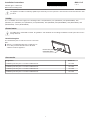
Identification plate
The identification plate is located next to the connection
plate.
Affix the second identification plate (supplied) in an
accessible position behind the front of the fitted
cabinet beneath the appliance.
Connection plate
Identification plate
Accessories
Designation Article no.
Ventilation protective plate set for niche width 550 mm H6.1082
Ventilation protective plate set for niche width 600 mm H6.1083
Ventilation protective plate set for niche width 825 mm H6.1084
Ventilation protective plate set for niche width 900 mm H6.1085
Installation instructions
J969.113-5
17.04.14
Induction glass ceramic hob
With normal mounting frame
1

Electrical connection
Electrical connections must be carried out by trained electricians in accordance with the guidelines and standards for low-
voltage installations and the specifications of the local electricity supply companies.
A plug-in appliance may only be connected to a socket outlet with earthing contact, installed according to specifications. An
all-pole mains isolating device with 3 mm contact opening should be provided in the house wiring system. Switches, plug
and socket devices, circuit breakers and fusible cut-outs which are accessible after installation and which have all-poles
switching are permissible as isolating devices. Effective earthing and separately installed neutral and earth conductors
ensure safe and fault-free operation. After installation, live parts and cables with basic insulation must not be accessible.
Check old installations.
The appliance is designed for use up to a max. altitude of 2000 m above sea level.
See the identification plate for information on the necessary mains voltage, type of current and fuse protection.
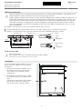
The appliance is equipped with a mains cable that should be connected to a distribution box by the customer.
600/550
900/825
Installation pipe
Distribution box
Clamp
brown + black
blue
yellow/green
black
blue
yellow/green
brown
L2
L1
N
N
L1
PE/
PE/
400 V 2N~
230 V~
Error message U400
Incorrect connection:
Pole conductor connected to connection terminal for neutral conductor.
Quickly disconnect the appliance from the mains!
Ventilation
In order to guarantee good ventilation, a space of
at least 17.5 mm in height is necessary beneath
the appliance.
1. The back wall of the base unit in the area of
the worktop cut-out must be open to guar-
antee continuous air circulation over the
ventilation slits.
2. Alternatively, air circulation inside the cabinet
can be provided for by a concealed fresh air
intake.
In order that enough cold air can be drawn in,
there must be a continuous circulation of
fresh air that extends outside the cabinet.
≥ 15
21
Installation instructions
J969.113-5
17.04.14
Induction glass ceramic hob
With normal mounting frame
2

Installation
Indications
• The worktop must be flat.
• In order to guarantee good ventilation, a space of at least 17.5 mm in height is necessary beneath the appliance.
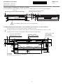
Fitting
The layout of the cooking zones on the hob to be built in may differ from the illustrated hob!
514
774
750 ±1
514
584
560 ±1
(30)
(30)
600/550
600
600
600/550
900/825
≥
50
490 ±1
≥
50
490 ±1
GK36TIC, GK46TIC, GK36TISC,
GK46TISC, GK46IDC, GK46TIMSC
GK46TIVC, GK46TIASC, GK46TIABSC,
GK46IABDC, GK46TIAKSC, GK46TIMASC
48
from level
For symmetrical fitting,
it is not necessary to
cut out the side walls.
aim for
≤ R10
aim for
≤ R10
48
from level
1. Create an accurate cut-out.
2. Carefully put the appliance in the installation cut-out and press against the worktop with sufficient overlap.
Installation instructions
J969.113-5
17.04.14
Induction glass ceramic hob
With normal mounting frame
3

Cool air intake if installed over a drawer or cabinet
In order to guarantee good ventilation, a space of at least 17.5 mm in height is necessary beneath the appliance.
≥ 5
≥ 15
(30)
600/550
900/825
≥ 25 cm²
≥ 48
≥ 65.5
Drawer Centre of fan
Air gap over the entire cabinet element width
Necessary space for the ventilation
below the worktop required
Hobs with dial control require protective intermediate base.
Installing the protective plate with a 3 mm ventilation gap at the front (see ’Accessories’)
A protective plate is necessary for the adequate ventilation of the hob.
The distance between the underside of the appliance and the protective plate must be at least 17.5 mm.
A protective plate cannot be installed with induction hobs that have dial controls.
393
(30)
≥ 67.5
5..10
55.5
56
Ø4
≥ 15
(19.5)
48
≥ 3
≤
0.5
2.5
Caution: mains cable
must not touch
protective plate!
Well-fitting seal over
width of cabinet element
Air gap over entire width of
cabinet element
≥ 17 cm²
According
to template
Drawer
Fan
Installation instructions
J969.113-5
17.04.14
Induction glass ceramic hob
With normal mounting frame
4
-
 1
1
-
 2
2
-
 3
3
-
 4
4


Ask a question and I''ll find the answer in the document
Finding information in a document is now easier with AI
Related papers
-
V-ZUG 488 Installation guide
-
V-ZUG 973 Installation guide
-
V-ZUG 31002 Installation guide
-
V-ZUG 619 Installation guide
-
V-ZUG 323 Installation guide
-
-
-
Whirlpool MWC-XSL/60 Mirror Installation guide
-
-