
User Manual
KN9000
2004-05-04

FCC Information
This is an FCC Class A product. In a domestic environment this product may cause
radio interference in which case the user may be required to take adequate measures.
This equipment has been tested and found to comply with the limits for a Class A
digital device, pursuant to Part 15 of the FCC Rules. These limits are designed to
provide reasonable protection against harmful interference when the equipment
is operated in a commercial environment. This equipment generates, uses and can
radiate radio frequency energy and, if not installed and used in accordance with
the instruction manual, may cause harmful interference to radio communications.
Operation of this equipment in a residential area is likely to cause harmful
interference in which case the user will be required to correct the interference at
his own expense.
© Copyright 2002-2004 ALTUSEN
®
All brand names and trademarks are the registered property of their respective owners.
2004-05-04

Package Contents
The complete KN9000 package contains the following components:
M 1 KN9000 KVM On the Net Control Unit
M 1 CS Custom KVM Cable Set
M 1 Rack Mounting Kit
M 1Software Disk
M 1Power Cord
M 1 User Manual
M 1 Quick Start Guide
M 1 Warranty Registration Card
Check to make sure that all the components are present and in good order. If
anything is missing, or was damaged in shipping, contact your dealer.
Read this manual thoroughly and follow the installation and operation
procedures carefully to prevent damage to the switch or any of the devices that
connect to it.
2004-05-04
iii

2004-05-04
iv

Contents
1. Introduction
Overview . . . . . . . . . . . . . . . . . . . . . . . . . . . . . . . . . 1
Features . . . . . . . . . . . . . . . . . . . . . . . . . . . . . . . . . . 3
System Requirements . . . . . . . . . . . . . . . . . . . . . . . . . . . 3
2. Hardware Setup
Components . . . . . . . . . . . . . . . . . . . . . . . . . . . . . . . 5
Front Panel . . . . . . . . . . . . . . . . . . . . . . . . . . . . . . 5
Rear Panel . . . . . . . . . . . . . . . . . . . . . . . . . . . . . . 6
Installation . . . . . . . . . . . . . . . . . . . . . . . . . . . . . . . . 7
3. The Administrator Utility
Installation . . . . . . . . . . . . . . . . . . . . . . . . . . . . . . . . 9
Starting Up . . . . . . . . . . . . . . . . . . . . . . . . . . . . . . . . 9
Logging In . . . . . . . . . . . . . . . . . . . . . . . . . . . . . . . 11
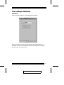
The Settings Notebook . . . . . . . . . . . . . . . . . . . . . . . . . 13
Overview . . . . . . . . . . . . . . . . . . . . . . . . . . . . . . 13
Uploading Changes . . . . . . . . . . . . . . . . . . . . . . . . . 14
General . . . . . . . . . . . . . . . . . . . . . . . . . . . . . . . 15
Network . . . . . . . . . . . . . . . . . . . . . . . . . . . . . . . 16
Security . . . . . . . . . . . . . . . . . . . . . . . . . . . . . . . 18
User Management . . . . . . . . . . . . . . . . . . . . . . . . . 21
Customization . . . . . . . . . . . . . . . . . . . . . . . . . . . . 23
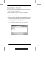
Upgrading the Firmware . . . . . . . . . . . . . . . . . . . . . . . . 24
Java Authentication Page . . . . . . . . . . . . . . . . . . . . . . . . 26
4. The Windows Client
Installation . . . . . . . . . . . . . . . . . . . . . . . . . . . . . . . 27
Starting Up . . . . . . . . . . . . . . . . . . . . . . . . . . . . . . . 27
The Connection Screen . . . . . . . . . . . . . . . . . . . . . . . 28
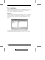
The Tools Menu . . . . . . . . . . . . . . . . . . . . . . . . . . . . 30
2004-05-04
v

Keyboard . . . . . . . . . . . . . . . . . . . . . . . . . . . . . . 30
Config . . . . . . . . . . . . . . . . . . . . . . . . . . . . . . . . 32
Connecting . . . . . . . . . . . . . . . . . . . . . . . . . . . . . . . 33
Operation . . . . . . . . . . . . . . . . . . . . . . . . . . . . . . . . 35
Screen Information . . . . . . . . . . . . . . . . . . . . . . . . . 35
Keystrokes . . . . . . . . . . . . . . . . . . . . . . . . . . . . . 36
Mouse Synchronization . . . . . . . . . . . . . . . . . . . . . . 36
Video Adjustment . . . . . . . . . . . . . . . . . . . . . . . . . 38
Work Files . . . . . . . . . . . . . . . . . . . . . . . . . . . . . . . 40
5. The Java Client
Introduction . . . . . . . . . . . . . . . . . . . . . . . . . . . . . . . 41
Starting Up . . . . . . . . . . . . . . . . . . . . . . . . . . . . . . . 41
Operation . . . . . . . . . . . . . . . . . . . . . . . . . . . . . . . . 44
The Toolbar . . . . . . . . . . . . . . . . . . . . . . . . . . . . . 45
6. The Log Server
Installation . . . . . . . . . . . . . . . . . . . . . . . . . . . . . . . 47
Starting Up . . . . . . . . . . . . . . . . . . . . . . . . . . . . . . . 48
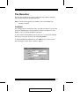
The Menu Bar . . . . . . . . . . . . . . . . . . . . . . . . . . . . . 49
Configure . . . . . . . . . . . . . . . . . . . . . . . . . . . . . . 49
Events . . . . . . . . . . . . . . . . . . . . . . . . . . . . . . . . 50
Options . . . . . . . . . . . . . . . . . . . . . . . . . . . . . . . 52
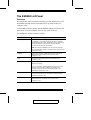
The KN9000 List Panel . . . . . . . . . . . . . . . . . . . . . . . . 53
Overview . . . . . . . . . . . . . . . . . . . . . . . . . . . . . . 53
The Event List Window . . . . . . . . . . . . . . . . . . . . . . . . 54
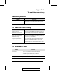
Appendix A. Troubleshooting
General Operation . . . . . . . . . . . . . . . . . . . . . . . . . . . 55
The Administration Utility . . . . . . . . . . . . . . . . . . . . . . . 55
The Windows Client . . . . . . . . . . . . . . . . . . . . . . . . . . 55
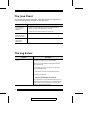
The Java Client . . . . . . . . . . . . . . . . . . . . . . . . . . . . . 56
The Log Server . . . . . . . . . . . . . . . . . . . . . . . . . . . . . 56
Sun Systems . . . . . . . . . . . . . . . . . . . . . . . . . . . . . . 57
2004-05-04
vi

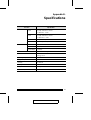
Appendix B. Specifications
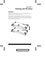
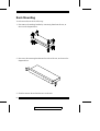
Appendix C. Stacking and Mounting
Stacking . . . . . . . . . . . . . . . . . . . . . . . . . . . . . . . . . 61
Rack Mounting . . . . . . . . . . . . . . . . . . . . . . . . . . . . . 62
Appendix D. Technical Support
ALTUSEN Technical Support . . . . . . . . . . . . . . . . . . . . . 63
ALTUSEN Website . . . . . . . . . . . . . . . . . . . . . . . . . . 64
Limited Warranty . . . . . . . . . . . . . . . . . . . . . . . . . . . . 64
2004-05-04
vii

About This Manual
This User Manual provides information concerning the installation,
configuration, and operation of the KN9000 16-Port LCD Console KVM
Switch.
Overview
Chapter 1, Introduction, introduces you to the KN9000 System. Its purpose,
features and benefits are described.
Chapter 2, Hardware Setup, presents the front and back panel components,
and explains how to connect the KN9000 to your server or KVM switch and the
Internet.
Chapter 3, The Administrator Utility, explains the Adminstrator Utility;
how to connect to the KN9000 as an administrator; and how to configure the
KN9000 for User operation.
Chapter 4, The Windows Client, explains how to run the Windows Client
Software; how to connect to the KN9000 and how to remotely control the
connected server (or servers via a KVM switch).
Chapter 5, The Java Client, explains how to run the Java Client Software;
how to connect to the KN9000 and how to remotely control the connected server
(or servers via a KVM switch).
Chapter 6, The Log Server, is used by the Administrator. It is a
Windows-based utility that records all the events that take place on the selected
KN9000 units and stores them in a searchable database.
Appendixes provide technical specifications and other helpful information.
2004-05-04
viii

Conventions
This manual uses the following conventions:
Courier
Indicates text that you should key in.
[ ]
Indicates keys you should press. For example, [Enter] means to
press the Enter key. If keys need to be chorded, they appear
together in the same bracket with a plus sign between them:
[Ctrl+Alt].
1.
Numbered lists represent procedures with sequential steps.
M
Bullet lists provide information
>
Indicates selecting an option on a menu. For example, Start >
Run means to open the Start menu, and then select Run.
Indicates critical information.
Getting Help
For additional help, advice, and information, ALTUSEN provides several
support options. If you need to contact ALTUSEN technical support with a
problem, please have the following information ready beforehand:
M Product model number, serial number, and date of purchase.
M Your computer configuration, including operating system, revision level,
expansion cards, and software.
M Any error messages displayed at the time the error occurred.
M The sequence of operations that led up to the error.
M Any other information you feel may be of help.
2004-05-04
ix

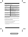
ALTUSEN Technical Support
North America Technical
Phone Support
Registered ALTUSEN product owners are entitled to
telephone technical support. Call the ALTUSEN
Technical Support Center: 949-453-8885.
International Technical Phone
Support
1. Contact your local dealer.
2. Call the ALTUSEN Technical Support Center:
1-949-453-8885.
Email Support Email your questions and concerns to:
Online Troubleshooting The ALTUSEN support website:
http://www.altusen.com/support
provides online troubeshooting that describes the
most commonly encountered problems and offers
possible solutions to them.
Online Documentation User Manuals are available electronically at the
ALTUSEN support website:
http://www.altusen.com/support
Software Updates Download the latest drivers and firmware for your
product from the ALTUSEN support website:
http://www.altusen.com/support
Product Information
For information about all of ALTUSEN’s products and how they can help you
connect without limits, visit ALTUSEN on the webat http://www.altusen.com
ALTUSEN Authorized Resellers
ALTUSEN provides the following ways to find an authorized reseller in your area:
M In the United States of America, call: 866-ALTUSEN
M In Canada and South America, call: 949-453-8885
M In all other locations, call: 886-2-8692-6789
M Visit ALTUSEN on the web at http://www.altusen.com for a list of locations
and telephone numbers
2004-05-04
x

Chapter 1.
Introduction
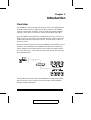
Overview
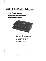
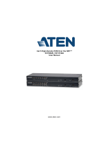
The KN9000 is a control unit that uses the IP protocol to allow administrators
to monitor and access their computers from remote locations. The KN9000
connects to the Internet, an Intranet, LAN, or WAN using industry standard
Category 5 cable; and to a local server or KVM switch using KVM cables.
Since the KN9000 uses TCP/IP for its communications protocol, the server or
KVM switch it is connected to can be accessed from any computer on the Net -
whether that computer is located down the hall, down the street, or half-way
around the world.
Operators at remote locations connect to the KN9000 via its IP address. Once a
connection to a KN9000 has been established and authorization granted, the
remote computers can exchange keyboard, video and mouse signals with the
server or KVM switch - just as if they were physically present and working on
the equipment directly.
Utilizing advanced security features, the KN9000 is the fastest, most reliable,
most cost effective way to remotely access and manage widely distributed
multiple computer installations.
KVM Switch
2004-05-04
1

The Administrator and Client utilites provided with the KN9000 package make
the KN9000 easy to install, maintain, and operate. System administrators can
handle a multitude of tasks with ease - from installing and running GUI
applications, to BIOS level troubleshooting, routine monitoring, concurrent
maintenance, system administration, rebooting and even pre-booting functions.
The Administrator Utility is used to configure the system; limit access from
remote computers; manage users; and maintain the system with firmware and
software module updates.
The Log Server records all the events that take place on selected KN9000 units
for the administrator to analyze.
On the client side, both a Windows GUI Client and a Java Client are provided
for IP connection and login to the KN9000 unit from anywhere on the net. The
client software allows the user to view and control the servers connected to the
KN9000. Inclusion of a Java-based client ensures that the KN9000 is platform
independent, and is able to work with all operating systems.
Once an operator successfully connects and logs in, his screen displays what is
running on the remote unit attached to the KN9000 (a KVM OSD display, a
server’s desktop, or a running program, for example) and he can control it from
his console just as if he were there.
2004-05-04
2

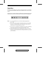
Features
M Remote access of KVM switches or servers via LAN, WAN, or the Internet;
control your installation from down the hall, down the street, or half-way
around the world
M Supports 10Base-T, 100Base-T, TCP/IP
M Advanced security features include password protection and advanced
encryption technologies
M High video resolution: up to 1280 x 1024 @ 60Hz
M Windows GUI and Java-based client software; Java client works with all
operating systems
M Upgradeable firmware via RJ45 Ethernet connection (with default F/W)
M Supports unlimited user accounts
System Requirements
M For best results we recommend that the computers used to access the the
KN9000 control unit have at least a P III 1 GHz processor, and that the
screen resolution is set to 1024 x 768.
M For the Windows Client, you must have DirectX 7.0 or higher installed.
M For the Java Client, you must have Sun’s Java 2 JRE 1.4 or higher.
M Only non-interlaced video signals at the following resolutions and refresh
rates are supported:
Resolution Refresh Rates
640 x 480 60, 70, 75, 85, 90, 100, 120
720 x 400 70, 75
800 x 600 56, 60, 70, 75, 85, 90, 100
1024 x 768 60, 70, 75, 85, 90, 100
1152 x 864 60, 70, 75
1280 x 1024 60
2004-05-04
3

Notes:
2004-05-04
4

Chapter 2.
Hardware Setup
Components
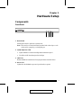
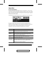
Front Panel
1. Reset Switch
Pressing this switch in performs a system reset.
Note: This switch is recessed and must be pushed with a thin object - such
as the end of a paper clip, or a ballpoint pen.
2. 10/100 Mbps Data LED
M Lights GREEN to indicate 100 Mbps data transmission speed.
M The LED is OFF when data speed is 10 Mbps.
3. Link LED
Flashes GREEN to indicate that a Client program has accessed the device.
4. Power LED
Lights when the KN9000 is powered up and ready to operate.
1 2 3 4
2004-05-04
5

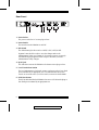
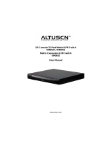
Rear Panel
1. Power Socket
The power cord to the AC source plugs in here.
2. Power Switch
This switch turns the KN9000 On and Off.
3. DIP Switch
The default setting for this switch is 1 OFF; 2 ON, 3 OFF; 4 OFF.
Segment 2 must be ON in order to save the changes made in the
Administration Utility (see Chapter 3). For security reasons, we strongly
recommend keeping Segment 2 OFF except for the times you make
Administration Utility changes.
4. RJ-45 Jack
The cable that connects the KN9000 to the Internet server plugs in here.
5. Local Console Port Section
The local administrator’s keyboard, monitor, and mouse plug in here. Each
port is indicated by an appropriate icon. The administrator can use this
console to access the server (or KVM switch) connected to the KN9000.
6. KVM Port Section
The KVM cable that links the KN9000 to the server or KVM switch tplugs in
here. Each port is indicated by an appropriate icon.
3 412
5 6
2004-05-04
6

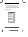
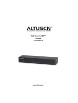
Installation
To install the KN9000, refer to the diagram below (the numbers correspond to the
numbered steps), and do the following:
1. Plug the local administrator’s keyboard, mouse, and monitor into the unit’s
Console Ports.
2. Use the KVM cable provided with this package to connect the Keyboard,
Video and Mouse ports from the KN9000’s KVM Port Section, to the
Keyboard, Video and Mouse ports of the server or KVM switch that you are
installing.
3. Plug the LAN or WAN cable into the KN9000’s RJ-45 socket.
4. Plug the power cord into the Power Socket and into an AC power source.
5. Power up your server or KVM installation.
6. Power up the KN9000.
1. Make sure that power to all the devices you will be connecting up
have been turned off. You must unplug the power cords of any
computers that have the Keyboard Power On function.
2. To prevent damage to your installation, make sure that all devices
on the installation are properly grounded.
KVM Switch
1
4
3
2
2004-05-04
7

Notes:
2004-05-04
8

Chapter 3.
The Administrator Utility
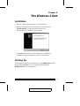
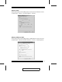
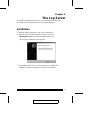
Installation
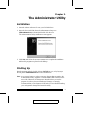
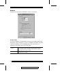
1. Insert the Altusen software CD into your CD-ROM drive
2. Open the drive and folder where the Administrator Setup icon
(kn9kadmintool.exe) is located and double click the icon.
The Administration Utility installation screen appears:
3. Click Next, and follow the on-screen instructions to complete the installation
and have the program icon placed on the desktop.
Starting Up
Run the program either by double clicking (DClick) its icon, or by keying in
the full path to kn9kadmintool.exe on the command line.
Note: As a security feature, in order to save any changes that are made to the
Administrator Utility, Segment 2 of the KN9000’s DIP Switch must be
set to ON. Otherwise, the changes are discarded when you exit the
program. In order to prevent unauthorized changes, we strongly
recommend that you set Segment 2 OFF after you have finished making
your configuration changes and exited the utility.
2004-05-04
9

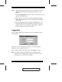
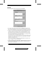
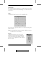
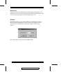
If this is the first time that you are running the utility a dialog box appears
requesting you to input your serial number. The serial number can be found on
the bottom panel of the KN9000. Key in the serial number - 5 characters per
box - then Click OK.
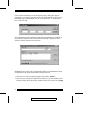
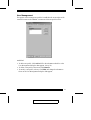
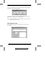
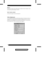
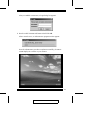
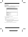
The Administrator Utility attempts to find all the KN9000 devices installed on
the local LAN segment. When it has finished searching, it displays a device
selection window similar to the one below:
KN9000 devices on the local LAN segment found by the Administrator Utility
are displayed in the large central listbox (KN9000 devices).
M If the unit you wish to configure appears in the listbox, Dclick it.
M If the unit you want doesn’t appear in the listbox, key in its IP address in the
KN9000 address field, and its Port number in the Port box, then Click Login.
2004-05-04
10
Page is loading ...
Page is loading ...
Page is loading ...
Page is loading ...
Page is loading ...
Page is loading ...
Page is loading ...
Page is loading ...
Page is loading ...
Page is loading ...
Page is loading ...
Page is loading ...
Page is loading ...
Page is loading ...
Page is loading ...
Page is loading ...
Page is loading ...
Page is loading ...
Page is loading ...
Page is loading ...
Page is loading ...
Page is loading ...
Page is loading ...
Page is loading ...
Page is loading ...
Page is loading ...
Page is loading ...
Page is loading ...
Page is loading ...
Page is loading ...
Page is loading ...
Page is loading ...
Page is loading ...
Page is loading ...
Page is loading ...
Page is loading ...
Page is loading ...
Page is loading ...
Page is loading ...
Page is loading ...
Page is loading ...
Page is loading ...
Page is loading ...
Page is loading ...
Page is loading ...
Page is loading ...
Page is loading ...
Page is loading ...
Page is loading ...
Page is loading ...
Page is loading ...
Page is loading ...
Page is loading ...
Page is loading ...
Page is loading ...
Page is loading ...
-
 1
1
-
 2
2
-
 3
3
-
 4
4
-
 5
5
-
 6
6
-
 7
7
-
 8
8
-
 9
9
-
 10
10
-
 11
11
-
 12
12
-
 13
13
-
 14
14
-
 15
15
-
 16
16
-
 17
17
-
 18
18
-
 19
19
-
 20
20
-
 21
21
-
 22
22
-
 23
23
-
 24
24
-
 25
25
-
 26
26
-
 27
27
-
 28
28
-
 29
29
-
 30
30
-
 31
31
-
 32
32
-
 33
33
-
 34
34
-
 35
35
-
 36
36
-
 37
37
-
 38
38
-
 39
39
-
 40
40
-
 41
41
-
 42
42
-
 43
43
-
 44
44
-
 45
45
-
 46
46
-
 47
47
-
 48
48
-
 49
49
-
 50
50
-
 51
51
-
 52
52
-
 53
53
-
 54
54
-
 55
55
-
 56
56
-
 57
57
-
 58
58
-
 59
59
-
 60
60
-
 61
61
-
 62
62
-
 63
63
-
 64
64
-
 65
65
-
 66
66
-
 67
67
-
 68
68
-
 69
69
-
 70
70
-
 71
71
-
 72
72
-
 73
73
-
 74
74
-
 75
75
-
 76
76


Ask a question and I''ll find the answer in the document
Finding information in a document is now easier with AI
Related papers
Other documents
-
 Altusen ALTUSEN PN0108 User manual
-
 Altusen KN2132 User manual
-
 Altusen KM0432 User manual
-
ATEN Technology KH1516i User manual
-
 Altusen KM0032 User manual
-
Altusen KN2132 User manual
-
 Altusen KVM Over the NET KN1000 User manual
-
 Altusen KH1508Ai User manual
-
 Altusen KH1508Ai User manual
-


