Page is loading ...

Version 19.03.2020 HW: GD(V100)/(V46) RL4-MBN55
r.LiNK Video inserter
RL4-MBN55
Compatible with Mercedes Benz vehicles with
Comand Online NTG5.5 with 10.25inch or 12inch monitor
and Audio 20 NTG5.5 with 7inch or 8.4inch monitor
with double Fakra connector at the head unit
Video-inserter for front- and rear-view camera
and two additional video inputs
Product features
• Video-inserter for factory-infotainment systems
• 1 CVBS Input for rear-view camera
• 1 CVBS Input for front camera
• 2 CVBS Video-inputs for after-market Video sources (e.g. USB-Player, DVB-T Tuner)
• Automatic switching to rear-view camera input on engagement of the reverse gear
• Automatic front camera switching after reverse gear for 10 seconds
• Activatable parking guide lines for rear-view camera (not available for all vehicles)
• Video-in-motion (ONLY for connected video-sources)
• Video-inputs NTSC and PAL compatible

Version 19.03.2020 HW: GD(V100)/(V46) RL4-MBN55
Page2
Contents
1. Prior to installation
1.1. Delivery contents
1.2. Checking the compatibility of vehicle and accessories
1.3. Boxes and connectors – video interface
1.4. Settings of the 8 dip switches (black)
1.4.1. Activating the front camera (dip 1)
1.4.2. Enabling the interface’s video inputs (dip 2-3)
1.4.3. Rear-view camera setting (dip 5)
1.4.4. Activating – front camera back-switching (dip 6)
1.4.5. Activating the guide lines Monitor selection (dip 7)
1.4.6. Monitor selection (dip 8)
1.5. Settings - 6 dip switches (Top of box–black)
1.6. Settings of the 4 dip switches (CAN function – red)
2. Installation
2.1. Place of installation
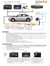
2.2. Connection schema
2.3. Connection - factory head unit
2.3.1. Connection - picture signal cable
2.3.1.1. Standard connection - picture signal cable (ocher coloured double Fakra)
2.3.1.2. Special case: Connection - picture signal cable (blue coloured double Fakra
2.3.2. Connection - Quadlock - CAN
2.4. Power/CAN connection for the video interface
2.5. Analog power supply for the video interface
2.6. Power supply output
2.7. Connection - video-sources
2.7.1. Audio insertion
2.7.2. After market front camera
2.7.3. After-market rear-view camera
2.7.3.1. Case 1: Interface receives the reverse gear signal
2.7.3.2. Case 2Interface does not receive the reverse gear signal
2.8. Connection - video-interface and external keypad
2.9. Picture settings and guide lines
3. Interface operation
3.1. By factory infotainment button
3.2. By keypad
4. Specifications
5. FAQ – Trouble Shooting-Interface functions
6. Technical support

Version 19.03.2020 HW: GD(V100)/(V46) RL4-MBN55
Page3
Legal Information
By law, watching moving pictures while driving is prohibited, the driver must not be
distracted. We do not accept any liability for material damage or personal injury resulting,
directly or indirectly, from installation or operation of this product. Apart from using this
product in an unmoved vehicle, it should only be used to display fixed menus or rear-view-
camera video when the vehicle is moving (for example the MP3 menu for DVD upgrades).
Changes/updates of the vehicle’s software can cause malfunctions of the interface. Up to
one year after purchase we offer free software-updates for our interfaces. To receive a free
update, the interface has to be sent in at own cost. Wages for de-and reinstallation and
other expenditures involved with the software-updates will not be refunded.
1. Prior to installation
Read the manual prior to installation. Technical knowledge is necessary for installation. The
video interface’s place of installation must be free of moisture and away from heat sources.
Before the final installation in the vehicle of the video sources, we recommend a test-run
to ensure the compatibility of vehicle and interface. Due to changes in the production of
the vehicle manufacturer there’s always a possibility of incompatibility.
1.1. Delivery contents
Take down the serial number of the interface and store this manual for support
purposes: ____________________

Version 19.03.2020 HW: GD(V100)/(V46) RL4-MBN55
Page4
Requirements
Brand
Compatible vehicles
Compatible systems
Mercedes Benz
C-class (W205) since about 07/2018
CLS-Coupé (C257) since 02/2018
E-class (W213) since 06/2016
E-class Coupé (A/C238) since 09/2017
G-model (G463) since 05/2018
GT AMG 4-Türer (X290) since 09/2018
S-Coupé (C217) since 05/2017, S-class
(V/X/W222) since 05/2017
Comand Online NTG 5.5 with
10.25inch or 12inch monitor
Audio 20 NTG 5.5 with
7inch or 8.4inch monitor
Limitations:
Video only The interface inserts ONLY video signals into the infotainment.
For inserting Audio signals either the possibly existing factory
audio-AUX-input or a FM-modulator can be used. If 2 audio
sources shall be connected to the infotainment, an additional
electronic is necessary to switch them.
Factory rear-view camera Automatically switching-back from inserted video to factory rear-
view camera is only possible while the reverse gear is engaged. To
delay the switch-back an additional electronic part is required.
After market front camera The front camera will automatically be switched for 10 seconds
after disengaging the reverse gear. A manually front camera
switching is possible by external keypad.
Guide lines Available only with 8.4inch monitor.
If the interface does not receive the required information from
the vehicle CAN-bus, guide lines won’t be supported.
1.2. Checking the compatibility of vehicle and accessories

Version 19.03.2020 HW: GD(V100)/(V46) RL4-MBN55
Page5
1.3. Boxes and connectors – video interface
The video-interface converts the video signals of connected after-market sources in a factory
monitor compatible picture signal which is inserted in the factory monitor, by using separate
trigger options. Further it reads the vehicle’s digital signals out of the vehicle’s CAN-bus and
converts them for the video interface.

Version 19.03.2020 HW: GD(V100)/(V46) RL4-MBN55
Page6
1.4. Settings of the 8 Dip switches (black)
Some settings have to be selected by the dip-switches on the
video interface.
Dip position UP = OFF and DOWN = ON.
*The front camera will automatically be switched for 10 seconds after disengaging the
reverse gear.
See the following chapters for detailed information.
Dip
Function
ON (down)
OFF (up)
1
Front camera
enabled*
disabled
Power supply
output
(red wire)
+12V (max. 3A) when reverse
gear is engaged incl. 10 seconds
delay and +12V by manual
switching to front camera by
keypad
+12V (max. 3A) ACC
2
CVBS Video 1-input
enabled
disabled
3
CVBS Video 2-input
enabled
disabled
4
No function
set to OFF
5
Rear-view cam
type
after-market
factory or none
6
*Frontcam
back-switching
for 10 seconds
*enabled
disabled
7
Guide lines
Enabled (8.4inch only)
disabled
8
Monitor selection
7 and 8.4inch monitors
10.25 and 12inch monitors

Version 19.03.2020 HW: GD(V100)/(V46) RL4-MBN55
Page7
1.4.1. Activating the front camera (dip 1)
If set to ON, the interface switches for 10 seconds from the rear-view camera to the front
camera input after having disengaged the reverse gear. In addition, a manual switch-over to
the front camera input is possible via keypad (short press) from any image mode.
Description of the power supply output: see chapter “Power supply output”.
1.4.2. Enabling the interface’s video inputs (dip 2-3)
Only the enabled video inputs can be accessed by switching through the interface’s video
sources. It is recommended to enable only the required inputs. So the disabled inputs will be
skipped while switching through the video interfaces inputs.
Note: Dip 4 is out of function and have to be set to OFF!
1.4.3. Rear-view camera setting (dip 5)
If set to OFF, the interface switches to factory picture while the reverse gear is engaged to
display factory rear-view camera or factory optical park system picture.
If set to ON, the interface switches to its rear-view camera input while the reverse gear is
engaged.
1.4.4. Activating – front camera back-switching (dip 6)
If set to ON, the interface switches for 10 seconds from the rear-view camera to the front
camera input after having disengaged the reverse gear. In addition, a manual switch-over to
the front camera input is possible via keypad (short press) from any image mode.
(Attend to correct adjustment of the power supply output (dip1)!
1.4.5. Activating the guidelines (dip 7)
If set to ON, the guidelines will be shown on the display (for 8.4inch monitors only). If set to
OFF, the guide lines won’t be visible on the display.
Note: If there is no communication between interface and the vehicle`s CAN-bus (several
vehicles aren’t compatible), the reverse gear guide-lines can`t be shown during the vehicle’s
operation, even if they once appear after having switched the system to powerless
1.4.6. Monitor selection (Dip 8)
Dip 8 customizes the monitor-specific video settings.
Dip switch setting ON customizes 7 and8.4inch monitors.
Dip switch setting OFF customizes 10.25 and 12inch monitors.
Please check, while a working video source is connected to the chosen input of the interface.
After each Dip-switch-change a power-reset of the Can-box has to be performed!

Version 19.03.2020 HW: GD(V100)/(V46) RL4-MBN55
Page8
1.5. Settings - 6 Dip switches (Top of box–black)
The 6 dip switches at the top of the video interface are responsible for
the according monitor assignment.
Attention: In contrast to both other dip benches (8dip and 4dip),
the 6dip position UP = ON and DOWN = OFF!
Monitor type and size
Dip 1
Dip 2
With Touch LCD
OFF
OFF
Without Touch LCD
ON
ON
Monitor type and size
Dip 3
Dip 4
Dip5
Dip6
7 and 8.4inch single monitors
ON
ON
ON
OFF
10 and 12inch single monitors
OFF
OFF
OFF
OFF
7inch dual monitors
OFF
ON
OFF
OFF
Note: Dip6 is out of function and has to be set to OFF.
After each Dip-switch-change a power-reset of the Can-box has to be performed!
1.6. Settings of the 4 Dip switches (CAN functions – red)
All 4 dip-switches of the video interface have no function for normal use and have
to be set to OFF (except W218 since 2018 –see league table).
Dip position UP = OFF and DOWN = ON.
Vehicle/Navigation
Dip 1
Dip 2
Dip 3
Dip 4
All vehicles
OFF
OFF
OFF
OFF
After each Dip-switch-change a power-reset of the video interface has to be performed!

Version 19.03.2020 HW: GD(V100)/(V46) RL4-MBN55
Page9
2. Installation
To install the interface, first switch off the ignition and disconnect the vehicle’s battery.
Please read the owner`s manual of the car, regarding the battery`s disconnection! If
required, enable the car`s Sleep-mode (hibernation mode)
In case the sleep-mode does not succeed, the disconnection of the battery can be done
with a resistor lead.
If the necessary stabilized power supply for the interface is not taken directly from the
battery, the chosen connection has to be checked for being constantly stabile.
The interface needs a permanent 12V source!
2.1. Place of installation
The interface is supposed to be installed at a suitable location behind the vehicle`s head-
unit.
Caution: On the G-model (W463), S-coupé (C217) and S-class (V/X/W222) the installation
location is behind the centre console. This means that the installation is considerably more
time-consuming (see picture).
The interface’s standard connection has to be done at the head unit’s ocher- coloured
double Fakra connector. As there are several Audio 20 NTG 5.5 head units without that
ocher- coloured double Fakra connector, this connection hast o be done at the blue
coloured double Fakra connector. In that case, the cables of each according double Fakra
connectors have to be exchanged. (refer to chapter „Special case: Connection to the picture
signal cable (blue coloured double Fakra”).

Version 19.03.2020 HW: GD(V100)/(V46) RL4-MBN55
Page10
2.2. Connection schema

Version 19.03.2020 HW: GD(V100)/(V46) RL4-MBN55
Page11
2.3. Connection - factory head-unit
Remove the head unit
2.3.1. Connection - factory head-unit
2.3.1.1. Standard connection - picture signal cable (ocher coloured double Fakra)
Connect the picture signal cable’s green female double Fakra connector to the male double
Fakra connector of the video interface.
Disconnect the ocher-coloured female double Fakra connector from the rear-side of the
head unit and connect it to the picture signal cable’s green-coloured male double Fakra
connector.
Connect the picture signal cable’s opposite green-coloured female double Fakra connector
to the ocher-coloured male double Fakra connector at the rear-side of the head unit.
Note: The double Fakra connectors of the head unit may not be save for confounding.
Please be sure to take attention for the right colouring (ocher)!

Version 19.03.2020 HW: GD(V100)/(V46) RL4-MBN55
Page12
2.3.1.2. Special case: Connection - picture signal cable (blue coloured double Fakra
As there are several Audio 20 NTG 5.5 head units without that ocher-coloured double Fakra
connector, this connection has to be done at the blue coloured double Fakra connector.
Connect the picture signal cable’s female green coloured double Fakra connector to the
double Fakra connector of the video interface.
Disconnect the blue coloured female double Fakra connector of the factory harness at the
rear-side of the head unit, unlock the connector’s locking mechanism, clip out both cables
to exchange them (see the blue diagram), clip in the exchanged cables and again lock the
connectors locking mechanism.
Connect the blue coloured female double Fakra connector of the factory harness (with previously
exchanged cables) to the picture signal cable’s green-coloured double Fakra connector.
Unlock the picture signal cable’s green-coloured double Fakra connector’s
„Connect behind head unit“ locking mechanism, clip out both cables to exchange them
(see the blue diagram), clip in the exchanged cables and again lock the connectors
locking mechanism (same procedure as done with the blue double Fakra connecter before).
Connect the picture signal cable’s green-coloured female double Fakra connector „Connect
behind head unit“ (with previously exchanged cables) to the head unit’s blue coloured
double Fakra connector.

Version 19.03.2020 HW: GD(V100)/(V46) RL4-MBN55
Page13
2.3.2. Connection - Quadlock - CAN
Connect the female 10pin connector of the 10pin Power / CAN cable to the 10pin connector
of the video interface.
Remove the female Quadlock connector of the vehicle harness
from the rear-side of the head-unit and connect the
previously clipped out white and black female 12pin
connectors to the white and black male 12pin
connector of the PNP harness (see graphic).
Clip in the white and black female 12pin connector of
the PNP harness in the previously become free
positions of the female Quadlock connector.
After that, finish the Quadlock reconnection at the rear-side
of the head-unit.

Version 19.03.2020 HW: GD(V100)/(V46) RL4-MBN55
Page14
2.4. Power/CAN connection for the video interface
Connect the single yellow wire of the 10pin power/CAN cable to +12V permanent and
stabile power supply.
Connect the single black wire of the 10pin power/CAN cable to the vehicle’s negative
ground.

Version 19.03.2020 HW: GD(V100)/(V46) RL4-MBN55
Page15
2.5. Analog power supply for the video interface
If, after connecting the PNP harness, no interface LED lightens up while the ignition is
turned on, the purple coloured wire Manual ACC of the 12pin interface cable has to
be connected additionately to ACC or S-contact terminal 86s +12V (e.g. glove
compartment illumination).

Version 19.03.2020 HW: GD(V100)/(V46) RL4-MBN55
Page16
2.6. Power supply output
The red power supply output ACC/front cam out 12V (max 3A) can be used to power an
external source and has a different assignment depending on the position of dip switch 1 (of
the black 8 dips):
Dip
Function
Dip 1 ON
+12V (max. 3A) when reverse gear is engaged incl. 10 seconds
delay after reverse gear is disengaged and
+12V by manual switching to front camera by keypad (short
press)
Dip 1 OFF
+12V (max. 3A) ACC

Version 19.03.2020 HW: GD(V100)/(V46) RL4-MBN55
Page17
2.7. Connection - video sources
It is possible to connect an after-market rear-view camera, an after-market front camera and
two more video sources to the video-interface.
Before a final installation of the video sources, we recommend a test-run to ensure the
compatibility of vehicle and interface. Due to changes in the production of the vehicle
manufacturer there’s always a possibility of incompatibility.
Connect the 12pin interface cable’s female 12pin connector to the male 12pin connector of
the video-interface.
Connect the video RCA of the Rear-view camera to the 12pin interface cable’s female
RCA connector „Reverse V4.
Connect the front camera’s video RCA connector to the 12pin interface cable’s female
RCA connector „Front V3“.
Connect the video RCA of the AV source 1 and 2 to the 12pin interface cable’s female RCA
connector “Left (V1)” and ”Right (V2)”.

Version 19.03.2020 HW: GD(V100)/(V46) RL4-MBN55
Page18
2.7.1. Audio-insertion
This interface is only able to insert video signals into the factory infotainment. If an AV-
source is connected, the audio insertion has to be done by the factory audio AUX input or an
FM-modulator. The inserted video-signal can be activated simultaneously to each audio-
mode of the factory infotainment. If 2 AV sources shall be connected to the infotainment,
additional electronic is necessary to switch the audio signals.
2.7.2. After-market front camera
The red power supply output ACC/front cam out 12V (max 3A) can be used to power
a front camera. If Dip 1 is set to ON (of the black 8 dips), the power supply output
gives +12V (max 3A) when reverse gear is engaged plus 10 seconds delay after
reverse gear is disengaged.
Note: In addition, a manual switch-over to the front camera input is possible via keypad
(short press) from any image mode. The power supply output gives +12V then, too (if Dip 1 is
set to ON and the front camera input is selected).

Version 19.03.2020 HW: GD(V100)/(V46) RL4-MBN55
Page19
2.7.3. After-market rear-view camera
Some vehicles have a different reverse gear code on the CAN-bus which the video-interface
is not compatible with. Therefore, there are two different ways of installation. If the video
interface receives a signal of the reverse gear, the green wire “Reverse-OUT” of the 20pin
cable should carry +12V while the reverse gear is engaged.
Note: Do not forget to set video interface’s dip5 to ON before testing.
2.7.3.1. Case 1: Interface receives the reverse gear signal
If the interface delivers +12V on the green output wire of the 12pin interface cable while
reverse gear is engaged, the video interface will automatically switch to the rear-view
camera input “Camera IN” while the reverse gear is engaged.
Additionally, the +12V (max. 3A) power supply for the rear-view camera can be taken
from the green wire of the 12pin interface cable.

Version 19.03.2020 HW: GD(V100)/(V46) RL4-MBN55
Page20
2.7.3.2. Case 2: Interface does not receive the reverse gear signal
If the video interface does not deliver +12V on the green wire of the 12pin cable when
reverse gear is engaged (not all vehicles are compatible), an external switching signal from
the reverse gear light is required. As the reverse gear light’s power supply isn’t voltage-
stabile all the time, an ordinary open relay (e.g AC-RW-1230 with wiring AC-RS5) or filter
(e.g. AC-PNF-RVC) is required. The diagram below shows the connection type of the relay.
Disconnect the green cable’s preconnected male- and female connectors of the 12pin
interface cable and connect the green input cable “Reverse-IN” to the output
connector (87) of the relay.
Note: Last but not lot least to avoid short circuits, the best solution should be, to
crimp a male 4mm connector to the relay’s output cable and connect it to the green
cable’s female 4mm connector. The output-cable “Reverse-OUT” remains
disconnected as it’s out of function.
Connect the Reverse light’s power-cable to coil (85) and the vehicle’s ground to coil
(86) of the relay.
Connect the output connector (87) of the relay to the rear-view camera’s power-
cable, like you did it to the green “Reverse-IN” cable before.
Connect stabile and permanent +12V to the relay’s input connector (30).
/