Page is loading ...

1
Q87WSA-DL
Q87WS-DL
H87WSA-DL
H87WS-DL
User Manual
Version 1.0
Published August 2013
Copyright©2013 ASRock INC. All rights reserved.

2
Copyright Notice:
No part of this manual may be reproduced, transcribed, transmitted, or translated in
any language, in any form or by any means, except duplication of documentation by
the purchaser for backup purpose, without written consent of ASRock Inc.
Products and corporate names appearing in this manual may or may not be regis-
tered trademarks or copyrights of their respective companies, and are used only for
Disclaimer:
-
tional use only and subject to change without notice, and should not be constructed
as a commitment by ASRock. ASRock assumes no responsibility for any errors or
omissions that may appear in this manual.
With respect to the contents of this manual, ASRock does not provide warranty of
any kind, either expressed or implied, including but not limited to the implied warran-
any indirect, special, incidental, or consequential damages (including damages for
even if ASRock has been advised of the possibility of such damages arising from
any defect or error in the manual or product.
This device complies with Part 15 of the FCC Rules. Operation is subject to the fol-
lowing two conditions:
may cause undesired operation.
CALIFORNIA, USA ONLY
The Lithium battery adopted on this motherboard contains Perchlorate, a toxic
passed by the California Legislature. When you discard the Lithium battery in Cali-
fornia, USA, please follow the related regulations in advance.
“Perchlorate Material-special handling may apply, see
www.dtsc.ca.gov/hazardouswaste/perchlorate”
ASRock Website: http://www.asrock.com

3
Contents
1 Introduction ........................................................ 5
1.1 Package Contents ......................................................... 5
................................................................. 6
1.3 Unique Features ............................................................ 9
1.4 Motherboard Layout ....................................................... 10
1.5 I/O
Panel ...................................................................... 11
1.6 Block Diagram ............................................................. 13
2 Installation .......................................................... 15
2.1 Screw Holes ................................................................... 15
2.2 Pre-installation Precautions ......................................... 15
2.3 CPU Installation ............................................................. 16
2.4 Installation of Heatsink and CPU fan ............................. 19
........................ 20
2.6 Expansion Slot
........................ 22
2.7 CrossFireX
TM
and Quad CrossFireX
TM
Operation Guide 23
2.8 Jumpers Setup .......................................................... 27
2.9 Onboard Headers and Connectors ............................ 28
2.10 Driver Installation Guide ............................................ 34
2.11 Intel
®
............... 34
2.12 Teaming Function Operation Guide ........................... 35
3 UEFI SETUP UTILITY .......................................... 37
3.1 Introduction .................................................................... 37
3.1.1 UEFI Menu Bar .................................................... 37
3.1.2 Navigation Keys ................................................... 38
3.2 Main Screen ................................................................... 38
3.3 OC Tweaker Screen ...................................................... 39
3.4 Advanced Screen ........................................................... 42
............................................... 43
........................................... 45
.......................................... 47
........................................ 49
............................................... 50
............................................... 51
3.4.7 Serial Port Console Redirection ........................... 52
............................................... 53
3.5 Tool ................................................................................ 55
3.6 Hardware Health Event Monitoring Screen ................... 56
3.7 Boot Screen ................................................................... 57
3.8 Security Screen ............................................................. 59

4
3.9 Exit Screen .................................................................... 60
3.10 Event Logs ..................................................................... 61
4 Software Support ............................................... 62
4.1 Install Operating System ................................................ 62
4.2 Support CD Information ................................................. 62
4.2.1 Running Support CD ............................................ 62
4.2.2 Drivers Menu ........................................................ 62
4.2.3 Utilities Menu........................................................ 62
4.2.4 Contact Information .............................................. 62
5 Trouble Shooting ................................................ 63
5.1 Troubleshooting Procedures .......................................... 63
5.2 Technical Support Procedures ....................................... 65
5.3 Returning Merchandise for Service ............................... 65

5
Chapter 1: Introduction
Thank you for purchasing ASRock Q87WSA-DL / Q87WS-DL / H87WSA-DL /
H87WS-DL-
tently stringent quality control. It delivers excellent performance with robust design
In this manual, chapter 1 and 2 contains introduction of the motherboard and step-
-
tion guide to BIOS setup and information of the Support CD.
updated, the content of this manual will be subject to change without no-
the latest VGA cards and CPU support lists on ASRock website as well.
ASRock website http://www.asrock.com
If you require technical support related to this motherboard, please visit
www.asrock.com/support/index.asp
1.1 Package Contents
ASRock Q87WSA-DL / Q87WS-DL / H87WSA-DL / H87WS-DL Motherboard
ASRock Q87WSA-DL / Q87WS-DL / H87WSA-DL / H87WS-DL User Manual
ASRock Q87WSA-DL / Q87WS-DL / H87WSA-DL / H87WS-DL Support CD
1 x I/O Panel Shield

6
Physical
Status
Form Factor ATX
Dimension
Processor
System
CPU
Supports Intel
®
Haswell i7, i5, i3 processors
* Intel
®
Xeon
®
E3-1200 v3 series processor
support is an extended advantage provided
by ASRock Rack. It is out of warranty, user's
discretion is required.
Socket
Power
Phase
4 power phase design
Chipset
Q87WSA-DL / Q87WS-DL:
Intel
®
Q87
Supports Intel
®
vPro
TM
Technology
Supports Intel
®
Active Management Technology
9.0
H87WSA-DL / H87WS-DL:
Intel
®
H87
BIOS BIOS Type 64Mb AMI UEFI Legal BIOS
System
Memory
Capacity 32GB DDR3 UDIMM
Socket 4 x 240-pin DDR3 DIMM slots
Type Dual Channel DDR3 1600/1333 UDIMM
Voltage 1.35V, 1.5V
Expansion
Slot
PCIe 3.0 x
16
PCIe 2.0 x
16
PCI 2 slots
Storage
SATA
Controller
Intel
®
Q87/H87: 6 x SATA3 6.0 Gb/s
Additional
SATA
Controller
ASMedia ASM1061: 2 x SATA3 6.0 Gb/s
Graphics
Controller
Intel
®
HD Graphics Built-in Visuals and the VGA
outputs can be supported only with processors
which are GPU integrated
VRAM Max. shared memory 1760MB
Output Max. 2048x1536 @ 75Hz

7
Audio Audio Codec
Q87WSA-DL / H87WSA-DL:
Realtek ALC662
Ethernet
Interface Gigabit LAN 10/100/1000 Mb/s
LAN
Controller
Q87WSA-DL / Q87WS-DL:
1 x Intel
®
i210, 1 x Intel
®
i217LM (with vPro
H87WSA-DL / H87WS-DL:
2 x Realtek RTL8111E VL
Supports Dual LAN with Teaming
Rear Panel
I/O
LAN Port
2
PS/2 KB/
Mouse
2
VGA Port 1 x D-Sub
USB 2.0
Port
4
USB 3.0
Port
2
COM Port 1
Audio
Q87WSA-DL / H87WSA-DL:
3 Jack
Internal
Connectors
COM Port
Header
1
Auxiliary
Panel
Header
1 (includes chassis intrusion, location button &
TPM Header 1
Front Panel
Audio
Header
Q87WSA-DL / H87WSA-DL:
1
HDMI_
SPDIF
Header
Q87WSA-DL / H87WSA-DL:
1
Fan Header
ATX Power
USB 2.0
Header
USB 3.0
Header

8
Support
OS
OS
Microsoft
®
Windows
®
:
7 32/64-bit / 8 32/64-bit
Linux:
- SUSE Enterprise Linux Server 11 SP1 (x32

9
1.3 Unique Features
ASRock Instant Flash
ROM. This convenient BIOS update tool allows you to update
DOS or Windows
®
. With this utility, you can press the <F6> key
during the POST or the <F2> key to enter into the BIOS setup
menu to access ASRock Instant Flash. Just launch this tool and
hard drive, then you can update your BIOS only in a few clicks
-

10
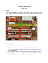
1.4 Motherboard Layout
1 ATX 12V Power Connector (ATX12V1)
2 CPU Fan Connector (CPU_FAN1)
3 CPU Fan Connector (CPU_FAN2)
4 1150-Pin CPU Socket
5 2 x 240-pin DDR3 DIMM Slots
(DDR3_A1, DDR3_B1, Blue)
6 2 x 240-pin DDR3 DIMM Slots
(DDR3_A2, DDR3_B2, White)
7 ATX Power Connector (ATXPWR1)
8 USB 3.0 Header (USB3_2_3)
9 Chassis Fan Connector (CHA_FAN2)
10 SPI Flash Memory (64Mb)
11 Intel Q87/H87 Chipset
12 Chassis Speaker Header (SPEAKER1)
13 Power LED Header (PLED1)
14 System Panel Header (PANEL1)
15 Auxiliary Panel Header (AUX_PANEL1)
16 SATA3 Connector (SATA3_5)
17 SATA3 Connector (SATA3_4)
18 SATA3 Connector (SATA3_3)
19 SATA3 Connector (SATA3_2)
20 SATA3 Connector (SATA3_1)
21 SATA3 Connector (SATA3_0)
22 SATA3 Connector (SATA3_A1)
23 SATA3 Connector (SATA3_A0)
24 USB 2.0 Header (USB8_9)
25 USB 2.0 Header (USB6_7)
26 USB 2.0 Header (USB4_5)
27 TPM Header (TPMS1)
28 COM Port Header (COM2)
29 PCI Slots (PCI1-2)
30 PCI Express 2.0 x16 Slot (PCIE3)
31 Clear CMOS Jumper (CLRCMOS1)
32 PCI Express 3.0 x16 Slot (PCIE6)
33 HDMI_SPDIF Header (HDMI_SPDIF2)*
34 Power Fan Connector (PWR_FAN1)
35 Front Panel Audio Header (HD_AUDIO2)*
36 Chassis Fan Connector (CHA_FAN1)
Intel
Q87/H87
SATA3_ A1
SATA3_ A0
64Mb
BIOS
DDR3_ A2 (6 4 bit , 240 -pin module)
DDR3_ A1 (6 4 bit , 240 -pin module)
DDR3_ B2 (6 4 bit , 240 -pin module)
DDR3_ B1 (6 4 bit , 240 -pin module)
ATX12 V1
CPU_ FAN1
CMOS
Batte ry
Super
I/O
ATXPWR1
1
USB 3_2_3
CPU_ FAN2
LAN
COM2
1
CLRC MOS1
1
USB4 _5
1
USB6 _7
1
HDLED RESET
PLED P WRBTN
PANEL1
1
PLED1
1
1
SPEAK ER1
PCIE6
PCI2
CHA_ FAN1
PWR_ FAN1
VGA1
USB 3.0
T: USB0
B: USB1
Top:
RJ-45
USB 2.0
T: USB0
B: USB1
24.4cm (9.6 in)
30.5cm (12.0 in)
1
2
3
4
5
6
7
8
9
11
10
12
13
14
17
19
15
16
20
21
22
23
24
25
26
27
28
29
30
31
32
33
34
Ro HS
PCI1
USB8 _9
1
PCIE3
LAN
PS2
Mouse
PS2
Keyboa rd
Top:
RJ-45
USB 2.0
T: USB2
B: USB3
CHA_ FAN2
TPMS 1
1
AUX_ PANEL1
1
SATA3_ 1
SATA3_ 0
SATA3_ 3
SATA3_ 2
SATA3_ 5
SATA3_ 4
COM2
18
Top:
LIN E I N
Cen ter:
FRO NT
Bot tom:
MIC IN
HD_ AUDIO 2
1
1
HDMI _SPDI F2
35
36
* HDMI_SPDIF header, front panel audio header, and the audio jacks on the I/O panel are for Q87WSA-DL
/ H87WSA-DL only.

11
1.5 I/O Panel
Q87WSA-DL / H87WSA-DL
* There are two LED next to the LAN port. Please refer to the table below for the LAN port LED
indications.
LAN Port LED Indications
Activity/Link LED SPEED LED
Status Description Status Description
Off No Link Off 10Mbps connection
Blinking Data Activity Orange 100Mbps connection
On Link Green 1Gbps connection
1 PS/2 Mouse Port (Green)
2 COM Port (COM1)
3 LAN RJ-45 Port (LAN1)*
4 LAN RJ-45 Port (LAN2)*
5 Line In (Light Blue)
6 Front Speaker (Lime)**
ACT/LINK
LED
SPEED
LED
LAN Port
7 Microphone (Pink)
8 USB 2.0 Ports (USB23)
9 USB 2.0 Ports (USB01)
10 USB 3.0 Ports (USB3_01)
11 VGA Port (VGA1)
12 PS/2 Keyboard Port (Purple)
1
2
4
3
5
6
7
9
812
11
10
** To enable Multi-Streaming function, you need to connect a front panel audio cable to the front
panel audio header. Please refer to below steps for the software setting of Multi-Streaming.
After restarting your computer, please double-click “Realtek HD Audio Manager” on the
advanced settings”, choose “Make front and rear output devices playbacks two different audio
streams simultaneously”, and click “ok”. Then reboot your system.

12
Q87WS-DL / H87WS-DL
* There are two LED next to the LAN port. Please refer to the table below for the LAN port LED
indications.
LAN Port LED Indications
Activity/Link LED SPEED LED
Status Description Status Description
Off No Link Off 10Mbps connection
Blinking Data Activity Orange 100Mbps connection
On Link Green 1Gbps connection
1 PS/2 Mouse Port (Green)
2 COM Port (COM1)
3 LAN RJ-45 Port (LAN1)*
4 LAN RJ-45 Port (LAN2)*
5 USB 2.0 Ports (USB23)
ACT/LINK
LED
SPEED
LED
LAN Port
6 USB 2.0 Ports (USB01)
7 USB 3.0 Ports (USB3_01)
8 VGA Port (VGA1)
9 PS/2 Keyboard Port (Purple)
1
2
4
3
5
6
7
9
8

13
1.6 Block Diagram
Q87WSA-DL / H87WSA-DL
BTN2194
QDJ!2
QDJ
33MHz
100MHz
EES4!21770244402711
TBUB3`6
Hawall
Joufm!Qspdfttps
MQD!CVT
SPI FLASH
64Mb
TQJ
TBUB3`4
TBUB3`3 TBUB3`5
TBUB!CVT
SFBMUFL!9222F
21021102111
Ijhi.Tqffe!VTC
Sfbs;5!!Gspou;7
33MHz
ENJ
MHB.2261!Qjo!Tpdlfu
Diboofm!C
591Nc0t!VTC3/1
TJP
Ovwpupo!ODU7887E
Lynx Point
239.cju!Evbm.Diboofm!Nfnpsz!y!5!Tmput
EES4!21770244402711
Diboofm!B
PCH
PCIE x1
100MHz
GEJ!MJOL
EES4!21770244402711
EES4!21770244402711
PCIE x1
100MHz
PCIE x1
100MHz
TBUB4`2
TBUB4`1
E.TVC!Dpoofdups
BOBMPH!QPSU
TBUB!CVT
Btnfejb!BTN2172
100MHz
PCIE BUS
TBUB4`B2
TBUB4`B1
QDJ!3
SFBMUFL!9222F
21021102111
QDJ.F!Y5!TMPU
PCIE x4
100MHz
Tvqfs.Tqffe!VTC
Sfbs;3!!Gspou;3
6Hc0t!VTC4/1
GJWS
WS!23/6
QDJ.F!Y27!TMPU!Hfo4
PCI_E BUS
JOUFM!J321
21021102111
JOUFM!J328
21021102111
GPS!I98GPS!R98
ALC662
B{bmjb!0BD:8
INTEL

14
BTN2194
QDJ!2
QDJ
33MHz
100MHz
EES4!21770244402711
TBUB3`6
Hawall
Joufm!Qspdfttps
MQD!CVT
SPI FLASH
64Mb
TQJ
TBUB3`4
TBUB3`3 TBUB3`5
TBUB!CVT
SFBMUFL!9222F
21021102111
Ijhi.Tqffe!VTC
Sfbs;5!!Gspou;7
33MHz
ENJ
MHB.2261!Qjo!Tpdlfu
Diboofm!C
591Nc0t!VTC3/1
TJP
Ovwpupo!ODU7887E
Lynx Point
239.cju!Evbm.Diboofm!Nfnpsz!y!5!Tmput
EES4!21770244402711
Diboofm!B
PCH
PCIE x1
100MHz
GEJ!MJOL
EES4!21770244402711
EES4!21770244402711
PCIE x1
100MHz
PCIE x1
100MHz
TBUB4`2
TBUB4`1
E.TVC!Dpoofdups
BOBMPH!QPSU
TBUB!CVT
Btnfejb!BTN2172
100MHz
PCIE BUS
TBUB4`B2TBUB4`B1
QDJ!3
SFBMUFL!9222F
21021102111
QDJ.F!Y5!TMPU
PCIE x4
100MHz
Tvqfs.Tqffe!VTC
Sfbs;3!!Gspou;3
6Hc0t!VTC4/1
GJWS
WS!23/6
QDJ.F!Y27!TMPU!Hfo4
PCI_E BUS
JOUFM!J321
21021102111
JOUFM!J328
21021102111
GPS!I98GPS!R98
INTEL
Q87WS-DL / H87WS-DL

15
Chapter 2: Installation
Make sure to unplug the power cord before installing or removing the
motherboard. Failure to do so may cause physical injuries to you and
damages to motherboard components.
2.1 Screw Holes
Place screws into the holes indicated by circles to secure the motherboard to the
chassis.
Do not over-tighten the screws! Doing so may damage the motherboard.
2.2 Pre-installation Precautions
Take note of the following precautions before you install motherboard components
or change any motherboard settings.
1. Unplug the power cord from the wall socket before touching any
components.
electricity, NEVER place your motherboard directly on the carpet
or the like. Also remember to use a grounded wrist strap or touch a
safety grounded object before you handle the components.
3. Hold components by the edges and do not touch the ICs.
4. Whenever you uninstall any component, place it on a grounded anti-
static pad or in the bag that comes with the component.
5. When placing screws into the screw holes to secure the mother-
board to the chassis, please do not over-tighten the screws! Doing
so may damage the motherboard.
Before you install or remove any component, ensure that the power is
switched off or the power cord is detached from the power supply. Failure to do
so may cause severe damage to the motherboard, peripherals, and/or
components.

16
2.3 Installing the CPU
2
1
A
B
1. Before you insert the 1150-Pin CPU into the socket, please check if the
PnP cap is on the socket, if the CPU surface is unclean, or if there are any
bent pins in the socket. Do not force to insert the CPU into the socket if
above situation is found. Otherwise, the CPU will be seriously damaged.
2. Unplug all power cables before installing the CPU.

17
4
5
3

18
Please save and replace the cover if the processor is removed. The cover
must be placed if you wish to return the motherboard for after service.

19
2.4 Installing the CPU Fan and Heatsink
1 2
CPU_
FAN

20
2.5 Installation of Memory Modules (DIMM)
slots, and supports Dual Channel Memory Technology.
2. It is unable to activate Dual Channel Memory Technology with
only one or three memory module installed.
3. It is not allowed to install a DDR or DDR2 memory module into a
DDR3 slot; otherwise, this motherboard and DIMM may be dam-
aged.
damage to the motherboard and the DIMM if you force the DIMM into
the slot at incorrect orientation.
Priority DDR3_A1 DDR3_A2 DDR3_B1 DDR3_B2
1 Populated Populated
2 Populated Populated
3 Populated Populated Populated Populated
/