Page is loading ...

1
C216 WS
User Manual
Version 1.0
Published December 2012
Copyright©2012 ASRock INC. All rights reserved.

2
Copyright Notice:
No part of this manual may be reproduced, transcribed, transmitted, or translated in
any language, in any form or by any means, except duplication of documentation by
the purchaser for backup purpose, without written consent of ASRock Inc.
Products and corporate names appearing in this manual may or may not be regis-
tered trademarks or copyrights of their respective companies, and are used only for
Disclaimer:
-
tional use only and subject to change without notice, and should not be constructed
as a commitment by ASRock. ASRock assumes no responsibility for any errors or
omissions that may appear in this manual.
With respect to the contents of this manual, ASRock does not provide warranty of
any kind, either expressed or implied, including but not limited to the implied warran-
any indirect, special, incidental, or consequential damages (including damages for
even if ASRock has been advised of the possibility of such damages arising from
any defect or error in the manual or product.
This device complies with Part 15 of the FCC Rules. Operation is subject to the fol-
lowing two conditions:
may cause undesired operation.
CALIFORNIA, USA ONLY
The Lithium battery adopted on this motherboard contains Perchlorate, a toxic
passed by the California Legislature. When you discard the Lithium battery in Cali-
fornia, USA, please follow the related regulations in advance.
“Perchlorate Material-special handling may apply, see
www.dtsc.ca.gov/hazardouswaste/perchlorate”
ASRock Website: http://www.asrock.com

3
Contents
1 Introduction ........................................................ 5
1.1 Package Contents ......................................................... 5
................................................................ 6
1.3 Unique Features ............................................................ 10
1.4 Motherboard Layout ...................................................... 11
1.5 I/O
Panel ...................................................................... 12
1.6 Block Diagram ............................................................. 14
2 Installation .......................................................... 15
2.1 Screw Holes ................................................................... 15
2.2 Pre-installation Precautions ......................................... 15
2.3 CPU Installation ............................................................. 16
2.4 Installation of Heatsink and CPU fan ............................. 18
........................ 19
2.6 Expansion Slots
.................... 21
2.7 CrossFireX
TM
, 3-Way CrossFireX
TM
and Quad
CrossFireX
TM
Operation Guide ....................................... 23
2.8 Surround Display Feature ............................................. 28
2.9 Jumpers Setup .......................................................... 31
2.10 Onboard Headers and Connectors ............................ 32
2.11 Dr. Debug ................................................................... 37
2.12 Teaming Function Operation Guide ............................ 38
3 UEFI SETUP UTILITY .......................................... 42
3.1 Introduction .................................................................... 42
3.1.1 UEFI Menu Bar .................................................... 42
3.1.2 Navigation Keys ................................................... 43
3.2 Main Screen ................................................................... 43
3.3 OC Tweaker Screen ...................................................... 44
3.4 Advanced Screen ........................................................... 49
............................................... 50
................................... 52
.................................. 53
............................... 54
........................................ 56
............................................... 57
............................................... 59
3.5 Tool ................................................................................ 60
3.6 Hardware Health Event Monitoring Screen ................... 61
3.7 Boot Screen ................................................................... 62
3.8 Security Screen ............................................................. 64

4
3.9 Exit Screen .................................................................... 65
4 Software Support ............................................... 66
4.1 Install Operating System ................................................ 66
4.2 Support CD Information ................................................. 66
4.2.1 Running Support CD ............................................ 66
4.2.2 Drivers Menu ........................................................ 66
4.2.3 Utilities Menu........................................................ 66
4.2.4 Contact Information .............................................. 66
5 Troubleshooting ................................................ 67
5.1 Troubleshooting Procedures .......................................... 67
5.2 Technical Support Procedures ....................................... 69
5.3 Returning Merchandise for Service ............................... 69

5
Chapter 1: Introduction
Thank you for purchasing ASRock C216 WS motherboard, a reliable motherboard
endurance.
In this manual, chapter 1 and 2 contains introduction of the motherboard and step-
-
tion guide to BIOS setup and information of the Support CD.
updated, the content of this manual will be subject to change without no-
the latest VGA cards and CPU support lists on ASRock website as well.
ASRock website http://www.asrock.com
If you require technical support related to this motherboard, please visit
www.asrock.com/support/index.asp
1.1 Package Contents
ASRock C216 WS Motherboard
ASRock C216 WS User Manual
ASRock C216 WS Support CD
1 x I/O Panel Shield
ASRock Reminds You...
To get better performance in Windows
®
8 / 8 64-bit / 7 / 7 64-bit, it is
mode.

6
- ATX Form Factor: 12.0-in x 9.6-in, 30.5 cm x 24.4 cm
- Premium Gold Capacitor design (100% Japan-made
high-quality Conductive Polymer Capacitors)
CPU - Intel
®
Socket 1155 for 3
rd
/2
nd
Generation Core
TM
i7/Core
TM
i5/
Core
TM
i3 Processors
- Intel
®
Socket 1155 for Intel
®
E3-1200/12x5 v2 processors
- Supports Intel
®
32 nm CPU
- Supports Intel
®
22 nm CPU
- Digi Power Design
- 8 + 4 Power Phase Design
- Supports Intel
®
Turbo Boost 2.0 Technology
- Intel
®
C216
- Dual Channel DDR3 Memory Technology
- 4 x DDR3 DIMM slots
- Supports DDR3 1600/1333/1066 ECC/non-ECC,
un-buffered memory
* ECC memory is supported with Xeon
®
E3 CPU only.
- Max. capacity of system memory: 32GB (see CAUTION 1)
- 2 x PCI Express 3.0 x16 slots (PCIE2/PCIE4: Single at x16
(PCIE2) mode or dual at x8 (PCIE2) / x8 (PCIE4) mode)
(see CAUTION 2)
* PCIE 3.0 is only supported with Intel
®
Ivy Bridge CPU. With
Intel
®
Sandy Bridge CPU, it only supports PCIE 2.0.
- 1 x PCI Express 2.0 x16 slot (PCIE5: x4 mode)
- 2 x PCI Express 2.0 x 1 slots
- 2 x PCI slots
- Supports AMD Quad CrossFireX
TM
, 3-Way CrossFireX
TM
and
CrossFireX
TM
* Intel
®
HD Graphics Built-in Visuals and the VGA outputs can
be supported only with processors which are GPU
integrated.
- Supports Intel
®
HD Graphics Built-in Visuals: Intel
®
Quick
Sync Video 2.0, Intel
®
InTru
TM
3D, Intel
®
Clear Video HD
Technology, Intel
®
Insider
TM
, Intel
®
HD Graphics 2500/4000
with Intel
®
Ivy Bridge CPU
- Supports Intel
®
HD Graphics Built-in Visuals: Intel
®
Quick
Sync Video, Intel
®
InTru
TM
3D, Intel
®
Clear Video HD
Technology, Intel
®
HD Graphics 2000/3000, Intel
®
Advanced
Vector Extensions (AVX) with Intel
®
Sandy Bridge CPU

7
- Pixel Shader 5.0, DirectX 11 with Intel
®
Ivy Bridge CPU.
Pixel Shader 4.1, DirectX 10.1 with Intel
®
Sandy Bridge
CPU.
- Max. shared memory 1760MB with Intel
®
Ivy Bridge CPU.
Max. shared memory 1759MB with Intel
®
Sandy Bridge
CPU.
- Supports HDMI 1.4a Technology with max. resolution up to
1920x1200 @ 60Hz
CAUTION 3
- Supports HDCP function with HDMI port
with HDMI port
Audio - 7.1 CH HD Audio with Content Protection
- Premium Blu-ray audio support
LAN - PCIE x1 Gigabit LAN 10/100/1000 Mb/s
- Broadcom BCM57781
- Supports Wake-On-LAN
- Supports Dual LAN with Teaming function
- Supports PXE
Storage - 2 x SATA3 6.0 Gb/s connectors by Intel
®
C216, support
RAID (RAID 0, RAID 1, RAID 5, RAID 10, Intel Rapid
and “Hot Plug” functions
- 4 x SATA3 6.0 Gb/s connectors by ASMedia ASM1061,
support NCQ, AHCI and “Hot Plug” functions (SATA3_A4
- 4 x SATA2 3.0 Gb/s connectors by Intel
®
C216, support
RAID (RAID 0, RAID 1, RAID 5, RAID 10, Intel Rapid
and Hot Plug functions
Rear Panel I/O I/O Panel
- 1 x PS/2 Keyboard/Mouse Port
- 1 x HDMI Port
- 1 x Optical SPDIF Out Port
- 4 x Ready-to-Use USB 2.0 Ports
- 1 x eSATA3 Connector
- 6 x Ready-to-Use USB 3.0 Ports

8
- 2 x RJ-45 LAN Ports with LED (ACT/LINK LED and SPEED
- 1 x IEEE 1394 Port
- HD Audio Jack: Rear Speaker/Central/Bass/Line in/Front
Speaker/Microphone
USB3.0 - 2 x Rear USB 3.0 ports by Intel
®
C216, support
USB 1.1/2.0/3.0 up to 5Gb/s
- 4 x Rear USB 3.0 ports by Etron EJ188H, support
USB 1.1/2.0/3.0 up to 5Gb/s
- 1 x Front USB 3.0 header by Intel
®
C216 (supports 2 USB 3.0
Connector - 1 x IR header
- 1 x COM port header
- 1 x HDMI_SPDIF header
- 1 x IEEE 1394 header
- 1 x Power LED header
- 24 pin ATX power connector
- 8 pin 12V power connector
- Front panel audio connector
BIOS Feature - 64Mb AMI UEFI Legal BIOS
- ACPI 1.1 Compliance Wake Up Events
- SMBIOS 2.3.1 Support
- CPU Core, IGPU, DRAM, 1.8V PLL, VTT, VCCSA Voltage
Multi-adjustment
Support CD - Drivers, Utilities, AntiVirus Software (Client OS, Trial
Hardware - CPU Temperature Sensing
Monitor - Chassis Temperature Sensing
- CPU/Chassis/Power Fan Tachometer
- CPU/Chassis Quiet Fan (Allows CPU Fan Speed Auto-
- CPU/Chassis Fan Multi-Speed Control
- Voltage Monitoring: +12V, +5V, +3.3V, CPU Vcore
OS - Microsoft
®
Windows
®
8 / 8 64-bit / 7 / 7 64-bit compliant

9
- FCC, CE, WHQL
* For detailed product information, please visit our website: http://www.asrock.com
WARNING
Please realize that there is a certain risk involved with overclocking,
including adjusting the setting in the BIOS, applying Untied Overclocking
Technology, or using third-party overclocking tools. Overclocking may
and devices of your system. It should be done at your own risk and
expense. We are not responsible for possible damage caused by
overclocking.
CAUTION!
1. Due to the operating system limitation, the actual memory size
may be less than 4GB for the reservation for system usage un-
der Windows
®
8 / 7. For Windows
®
OS with 64-bit CPU, there is
no such limitation.
2. Only PCIE2 and PCIE4 slots support Gen 3 speed. To run the
PCI Express in Gen 3 speed, please install an Ivy Bridge CPU.
If you install a Sandy Bridge CPU, the PCI Express will run only
at PCI Express Gen 2 speed.
3. xvYCC and Deep Color are only supported under Windows
®
8
64-bit / 8 / 7 64-bit / 7. Deep Color mode will be enabled only
if the display supports 12bpc in EDID. HBR is supported under
Windows
®
8 64-bit / 8 / 7 64-bit / 7.

10
1.3 Unique Features
ASRock Instant Flash
ROM. This convenient BIOS update tool allows you to update
DOS or Windows
®
. With this utility, you can press the <F6> key
during the POST or the <F2> key to enter into the BIOS setup
menu to access ASRock Instant Flash. Just launch this tool and
hard drive, then you can update your BIOS only in a few clicks
-
ASRock Crashless BIOS
ASRock Crashless BIOS allows users to update their BIOS
without fear of failing. If power loss occurs during the BIOS up-
the BIOS update procedure after regaining power. Please note
USB disk. Only USB2.0 ports support this feature.

11
1.4 Motherboard Layout
1 1155-Pin CPU Socket
2 ATX 12V Power Connector (ATX12V1)
3 CPU Fan Connector (CPU_FAN1)
4 CPU Fan Connector (CPU_FAN2)
5 2 x 240-pin DDR3 DIMM Slots
(DDR3_A1, DDR3_B1)
6 2 x 240-pin DDR3 DIMM Slots
(DDR3_A2, DDR3_B2)
7 ATX Power Connector (ATXPWR1)
8 USB 3.0 Header (USB3_6_7)
9 Intel C216 Chipset
10 SATA3 Connectors (SATA3_A3_A4)
11 SATA3 Connectors (SATA3_A1_A2)
12 SATA3 Connectors (SATA3_0_1)
13 SATA2 Connectors (SATA2_2_3)
14 SATA2 Connectors (SATA2_4_5)
15 Dr. Debug
16 Power LED Header (PLED1)
17 Chassis Speaker Header (SPEAKER1)
18 System Panel Header (PANEL1)
19 Chassis Fan Connector (CHA_FAN3)
20 USB 2.0 Header (USB_6_7)
21 USB 2.0 Header (USB_8_9)
22 Chassis Fan Connector (CHA_FAN1)
23 Clear CMOS Jumper (CLRCMOS1)
24 Front Panel IEEE 1394 Header
(FRONT_1394)
25 Infrared Module Header (IR1)
26 COM Port Header (COM1)
27 Front Panel Audio Header (HD_AUDIO1)
28 HDMI_SPDIF Header (HDMI_SPDIF1)
29 PCI Express 2.0 x16 Slot (PCIE5)
30 PCI Slot (PCI2)
31 PCI Express 3.0 x16 Slot (PCIE4)
32 PCI Express 2.0 x1 Slot (PCIE3)
33 PCI Slot (PCI1)
34 PCI Express 3.0 x16 Slot (PCIE2)
35 PCI Express 2.0 x1 Slot (PCIE1)
36 Power Fan Connector (PWR_FAN1)
37 Chassis Fan Connector (CHA_FAN2)
Intel
C216
CMOS
Batte ry
DDR3_ A1 (64 bit, 24 0-pin module)
DDR3_ A2 (64 bit, 24 0-pin module)
DDR3_ B1 (64 bit, 24 0-pin module)
DDR3_ B2 (64 bit, 24 0-pin module)
ATXPWR1
64Mb
BIOS
USB 3_6_7
24.4cm (9.6 in)
30.5cm (12.0 in)
C216 WS
PWR_ FAN1
ATX12 V1
CHA_ FAN2
CPU_ FAN2
CPU_FA N1
PCI Expre ss 3.0
AUDI O
CODE C
LAN
PHY
LAN
PHY
Super
I/O
PCIE1
PCIE2
PCIE4
PCIE5
PCIE3
PCI1
PCI2
RoHS
1
HD_A UDIO1
COM1
1
CHA_ FAN1
1
HDMI_ SPDIF 1
IR1
1
USB8 _9
1
USB6 _7
1
FRON T_139 4
1
CLRCM OS1
1
HDLED RES ET
PLED PW RBTN
PANEL1
1
SPEAKE R1
1
PLED1
1
CHA_ FAN3
SATA2_ 4_5 SATA2_ 2_3 SATA3_ 0_1 S ATA3 _A1_A 2 SATA3_ A3_A4
PS2
Keyb oard/
Mous e
USB 3 .0
T: USB0
B: US B1
HDM I1
USB 2 .0: USB 2
USB 2 .0: USB 3
Top:
RJ- 45
USB 3 .0
T: USB2
B: US B3
USB 2 .0
T: USB4
B: US B5
ESATA_ 1
IEE E 1394
Top:
RJ- 45
USB 3 .0
T: USB4
B: US B5
Top:
Cen tral/ Bass
Cen ter:
REA R S PK
Top:
LIN E I N
Cen ter:
FRO NT
Bot tom:
Opti cal
SPD IF
Bot tom:
MIC I N
1
2
3
4
5
6
7
11
12
13
14
16
8
9
10
15
17
181920
21
22
23
24
25
2627
28
29
30
31
32
33
34
35
36
37
Dr.
Debug

12
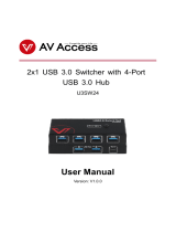
1.5 I/O Panel
* There are two LED next to the LAN port. Please refer to the table below for the LAN port LED
indications.
LAN Port LED Indications
Activity/Link LED SPEED LED
Status Description Status Description
Off No Link Off 10Mbps connection
Blinking Data Activity Orange 100Mbps connection
On Link Green 1Gbps connection
1 PS/2 Keyboard/Mouse Port (Purple/Green) 10 Microphone (Pink)
* 2 LAN RJ-45 Port 11 USB 3.0 Ports (USB3_45)
3 USB 2.0 Ports (USB45) 12 IEEE 1394 Port
* 4 LAN RJ-45 Port *** 13 eSATA3 Port (ESATA_1)
5 Central / Bass (Orange) 14 USB 3.0 Ports (USB3_23)
6 Rear Speaker (Black) 15 USB 2.0 Ports (USB23)
7 Optical SPDIF Out Port 16 HDMI Port (HDMI1)
8 Line In (Light Blue) 17 USB 3.0 Ports (USB3_01)
** 9 Front Speaker (Lime)
ACT/LINK
LED
SPEED
LED
LAN Port
**
See the table below for connection details in accordance with the type of speaker you use.
TABLE for Audio Output Connection
Audio Output Channels Front Speaker Rear Speaker Central / Bass Line In or
2 V -- -- --
4 V V -- --
6 V V V --
8 V V V V
12
13
14
15
16
17
5
4
1
2
3
6
7
8
9
10
11

13
To enable Multi-Streaming function, you need to connect a front panel audio cable to the front
Please select “Mixer ToolBox” , click “Enable playback multi-streaming”, and click
“ok”. Choose “2CH”, “4CH”, “6CH”, or “8CH” and then you are allowed to select “Realtek HDA
Primary output” to use Rear Speaker, Central/Bass, and Front Speaker, or select “Realtek
HDA Audio 2nd output” to use front panel audio.
*** eSATA3 connector supports SATA Gen3 in cable 1M.

14
1.6 Block Diagram
WSE!23
po!Cpbse
Ivy Bridge
Joufm!Qspdfttps
MQD!CVT
TBUB4`1
QDJF!y2
TBUB3`3TBUB3`5
TBUB4`2TBUB3`4
TBUB!CVT
Ijhi.Tqffe!VTC
9!qpsut
33MHz
ENJ
MHB.2266!Qjo!Tpdlfu
Diboofm!C
591Nc0t
TJP
Ovwpupo!ODU7887
Panther Point
QDJ.F!Y27!TMPU
24MHz
Sfbmufl!BMD9:3
239.cju!Evbm.Diboofm!Nfnpsz!y!5!Tmput
EES4!2177024440271103244
Diboofm!B
PCH
PCI_E BUS
100MHz
PCIE x4
100MHz
EES4!2177024440271103244
GEJ!MJOL
TBUB3`6
QDJ.F!Y9!TMPU
PCIE x1
100MHz
3!Gspou!VTC4!qpsut
QMY9719
QDJ!2 QDJ!3
100MHz
QDJ.F!Y5
QDJFy2
100MHz
BTN2194
CSPBEDPN!68892
PCIE x1
100MHz
21021102111
3!sfbs!VTC4!qpsut
QDJ
33MHz
WU7441
PCIE x1
100MHz
24:5!Qpsut!y!3
PCIE x1
100MHz
PCIE x1
100MHz
QDJ.F!Y2
QDJ.F!Y2
SPI
fTBUB4`2!)tibsfe*
TBUB4`B5!)tibsfe*
TBUB4`B4
TBUB!CVT
rvjdl!
txjudi
Btnfejb!BN2172
SPI FLASH
64Mb
100MHz
Intel
C216
DIGITAL PORT D
IENJ!Dpoofdups
Btnfejb!BN2172
100MHz
QDJF!y2
TBUB4`B3
TBUB4`B2
TBUB!CVT
Etron EJ188
QDJF!y2
100MHz
5!sfbs!VTC4!qpsut
CSPBEDPN!68892
21021102111
PCIE x1
100MHz
DPN!qpsu!'!JS

15
Chapter 2: Installation
Make sure to unplug the power cord before installing or removing the
motherboard. Failure to do so may cause physical injuries to you and
damages to motherboard components.
2.1 Screw Holes
Place screws into the holes indicated by circles to secure the motherboard to the
chassis.
Do not over-tighten the screws! Doing so may damage the motherboard.
2.2 Pre-installation Precautions
Take note of the following precautions before you install motherboard components
or change any motherboard settings.
1. Unplug the power cord from the wall socket before touching any
components.
electricity, NEVER place your motherboard directly on the carpet
or the like. Also remember to use a grounded wrist strap or touch a
safety grounded object before you handle the components.
3. Hold components by the edges and do not touch the ICs.
4. Whenever you uninstall any component, place it on a grounded anti-
static pad or in the bag that comes with the component.
5. When placing screws into the screw holes to secure the mother-
board to the chassis, please do not over-tighten the screws! Doing
so may damage the motherboard.
Before you install or remove any component, ensure that the power is
switched off or the power cord is detached from the power supply. Failure to do
so may cause severe damage to the motherboard, peripherals, and/or
components.

16
1155-Pin Socket Overview
2.3 CPU Installation
In order to provide the LGA 1155 CPU sock-
ets more protection and make the instal-
lation process easier, ASRock has added
a new protection cover on top of the load
plate to replace the former PnP caps that
were under the load plate. For the installa-
tion of Intel
®
1155-Pin CPUs with the new
protection cover, please follow the steps
below.
Before you insert the 1155-Pin CPU into the socket, please check if the
CPU surface is unclean or if there are any bent pins in the socket. Do
not force to insert the CPU into the socket if above situation is found.
Otherwise, the CPU will be seriously damaged.
Step 1. Open the socket:
Step 1-1. Disengage the lever by pressing it
down and sliding it out of the hook.
You do not have to remove the pro-
tection cover.
Step 1-2. Keep the lever positioned at about
135 degrees in order to flip up the
load plate.
Step 2. Insert the 1155-Pin CPU:
Step 2-1. Hold the CPU by the edge which is
marked with a black line.
Step 2-2. Orient the CPU with the IHS (Inte-
and the two orientation key notches.
Load
Plate
Cover
Contact
Array
Load
Lever
Socket
Body
black line

17
Pin1
alignment key
alignment key
Pin1
1155-Pin CPU
For proper installation, please ensure to match the two orientation
key notches of the CPU with the two alignment keys of the socket.
Step 2-3. Carefully place the CPU into the
socket.
Step 2-4. Verify that the CPU is within the sock-
et and properly mated to the orient
keys.
Step 3. Close the socket:
Step 3-1. Flip the load plate onto the IHS.
Step 3-2. Press down the load lever, and se-
cure it with the load plate tab under
the retention tab. The protection
cover will automatically come off by
itself.
Please save and replace the cover if the processor is removed. The
cover must be placed if you wish to return the motherboard for after
service.
orientation key notch
orientation key notch
1155-Pin Socket

18
2.4 Installation of CPU Fan and Heatsink
This motherboard is equipped with 1155-Pin socket that supports Intel 1155-Pin
CPUs. Please adopt the type of heatsink and cooling fan compliant with Intel 1155-
Pin CPU to dissipate heat. Before you install the heatsink, you need to spray ther-
mal interface material between the CPU and the heatsink to improve heat dissipa-
tion. Ensure that the CPU and the heatsink are securely fastened and in good con-
tact with each other. Then connect the CPU fan to the CPU_FAN connector (CPU_
For proper installation, please kindly refer to the instruction manuals of your
CPU fan and heatsink.
Below is an example to illustrate the installation of the heatsink for 1155-Pin CPUs.
Step 1. Apply thermal interface material onto the cen-
Step 2. Place the heatsink onto the socket. Ensure
that the fan cables are oriented on side closest
to the CPU fan connector on the motherboard
(CPU_FAN1, see page 11, No. 3 or CPU_
Step 3. Align fasteners with the motherboard through-
holes.
Step 4. Rotate the fastener clockwise, then press
down on fastener caps with thumb to install
and lock. Repeat with remaining fasteners.
If you press down the fasteners without rotating them clockwise, the
heatsink cannot be secured on the motherboard.
Step 5. Connect fan header with the CPU fan connector on the motherboard.
Step 6. Secure redundant cable with tie-wrap to ensure the cable does not
interfere with fan operation or contact other components.
Apply Ther mal
Interface Ma terial
Fan cables on side
closest to MB header
Fastener slo ts
pointing straight o ut
Press Down
(4 Places)
Please be noticed that this motherboard supports Combo Cooler
-
ferent CPU cooler types, Socket LGA 775, LGA 1155 and LGA 1156.
The white throughholes are for Socket LGA
1155/1156 CPU fan.

19
2.5 Installation of Memory Modules (DIMM)
-
uration, you always need to install identical (the same brand, speed, size and
identical DDR3
DIMMs in Dual Channel A (DDR3_A1 and DDR3_B1; Black slots; see p.11
identical DDR3 DIMMs in Dual Channel B (DDR3_A2 and DDR3_
be activated. This motherboard also allows you to install four DDR3 DIMMs
identical DDR3 DIMMs in all four
DDR3_A1 DDR3_A2 DDR3_B1 DDR3_B2
*
identical DDR3 DIMMs in all four
slots.
1. If you want to install two memory modules, for optimal compatibility
and reliability, it is recommended to install them in the slots: DDR3_
A1 and DDR3_B1, or DDR3_A2 and DDR3_B2.
2. If only one memory module or three memory modules are installed
in the DDR3 DIMM slots on this motherboard, it is unable to activate
Dual Channel Memory Technology.
3. If a pair of memory modules is NOT installed in the same Dual
Channel, for example, installing a pair of memory modules in
DDR3_A1 and DDR3_A2, it is unable to activate Dual Channel
Memory Technology.
4. It is not allowed to install a DDR or DDR2 memory module into
DDR3 slot; otherwise, this motherboard and DIMM may be dam-
aged.
5. Some DDR3 1GB double-sided DIMMs with 16 chips may not work
on this motherboard. It is not recommended to install them on this
motherboard.
6. For optimal compatibility and stability while overclocking memory
frequency, it is recommended to install one memory module on
DDR3_B2 slot or two memory modules on DDR3_A2 and DDR3_
B2 slots.

20
Installing a DIMM
Please make sure to disconnect power supply before adding or
removing DIMMs or the system components.
Step 1. Unlock a DIMM slot by pressing the retaining clips outward.
Step 2. Align a DIMM on the slot such that the notch on the DIMM matches the
break on the slot.
damage to the motherboard and the DIMM if you force the DIMM into
the slot at incorrect orientation.
Step 3. Firmly insert the DIMM into the slot until the retaining clips at both ends
fully snap back in place and the DIMM is properly seated.
notch
break
notch
break
/