Page is loading ...

IC100CX
1592022550 Quick reference guide IC100CX GB rel.1.0 03/03/2008 Page 1 di 39
dIXEL
iCHiLL 100CX
Quick reference guide

IC100CX
1592022550 Quick reference guide IC100CX GB rel.1.0 03/03/2008 Page 2 di 39
INDEX
1. General Advices _________________________ 2
2. User Interface ___________________________ 3
3. Remote Keyboard VICX610 ________________ 4
4. Display visualization______________________ 5
5. Silencing the Buzzer______________________ 5
6. First Installing___________________________ 5
7. How to Set the Clock RTC _________________ 5
8. “ Hot Key” Programming __________________ 5
9. Parameters Programming _________________ 6
10. How to Change the Password ______________ 6
11. Start / Stop Chiller or Heat Pump____________ 6
12. Stand- By Function_______________________ 7
13. “menu” Function ________________________ 7
14. Keyboard Functions______________________ 8
15. Black Out_______________________________ 8
16. Installing and Mounting ___________________ 9
17. Electrical Wiring ________________________ 11
18. Alarm Code and Events __________________ 12
19. Connecting Diagram_____________________ 19
20. Parameter Table ________________________ 22
21. Technical Data _________________________ 39
1. GENERAL ADVICES
• Please read this manual before using
• This manual is part of the product and should be kept near the
instrument for easy and quick reference.
• The instrument shall not be used for purposes different from
those described hereunder. It cannot be used as a safety
device.
• Check the application limits before proceeding.
1.1 Safety Precaution
• Check the supply voltage is correct before connecting the
instrument.
• Do not expose to water or moisture: use the controller only
within the operating limits avoiding sudden temperature
changes with high atmospheric humidity to prevent
formation of condensation
• Warning: disconnect all electrical connections before any
kind of maintenance.
• Fit the probe where it is not accessible by the End User. The
instrument must not be opened.
• In case of failure or faulty operation send the instrument
back to the distributor or to “Dixell s.r.l.” (see address) with a
detailed description of the fault.
• Consider the maximum current which can be applied to each
relay (see Technical Data).
• Ensure that the wires for probes, loads and the power supply
are separated and far enough from each other, without
crossing or intertwining.
• In case of applications in industrial environments, the use of
mains filters (our mod. FT1) in parallel with inductive loads
could be useful.
1.2
full Manual
Dixell S.p.A. reserves the right to modify or improve this
manual without prior notice.
The complete manual can be requested at the following
email address.

IC100CX
1592022550 Quick reference guide IC100CX GB rel.1.0 03/03/2008 Page 3 di 39
2. USER INTERFACE
2.1 Display
Upper digits (red color): configurable, see parameter
CF36 (PB1, PB2, PB4, Set-point (parameter value)*,
working set-point (real set-point modified from dinamic set-
point, Energy saving or function for units without water
storage tank), Hysteresis, Machine status **))
Lower digits (yellow color): configurable, see parameter
CF43 (PB1, PB2, PB3, PB4, Set-point (parameter value)*,
working set-point (real set-point modified from dinamic set-
point, Energy saving or function for units without water
storage tank), Hysteresis, RTC, Machine status **)).
*the display visualizes chiller set point when the unit is on
and in chiller mode, heating set point when the unit is on
and in heat pump mode, and OFF when the unit is in
standby.
**the display visualizes OnC when the unit is on and in
chiller mode, OnH when the unit is on and in heat pump
mode, and OFF when the unit is in standby.
2.2 Icons of the Display
Icon Meaning
°C -°F
bar-PSI
ON when the display visualizes a temperature
or a pressure
On when the display visualizes the RTC,
working hours, etc.
On flashing in case of alarm
On if the Energy Saving, dynamic set-point
or function for units without water storage
tank are active.
OFF if a function above is enabled but not
active.
On during menù visualization
On if heaters are activated (antifreeze
heaters or/and boiler)
On flashing during defrost delay time.
On during defrost
On flashing if water flow switch is activated.
When the pump is OFF, the led is on flashing
to indicate the correct status of the digital
input
On if at least one water pump is on
On if evaporator fans are activated
On if a compressor is on.
On flashing during the delay time for
compressor activation.
On if open collector output is active
On if the controller is on in Heat or Cool
mode
On in case of Low pressure alarm or High
pressure alarm
2.3 Keys
1. Push to enter in the Menu
2. Push and hold (about 3 seconds)
to set the clock
1. Push to visualize the set point.
2. Push and release 2 times: 1
st
time is visualized the setpoint (the
value of the parameter), 2
nd
time
is visualized the real setpoint
(when Energy saving, Dynamic
setpoint or function for units
without water storage tank are
enebled)
3. Push and hold to modify the
setpoint
4. Push during parameter
programming:
- to enter in parameter
modification
- to confirm the changes of the
parameter
5. Menù AlrM: push to reset
the alarms

IC100CX
1592022550 Quick reference guide IC100CX GB rel.1.0 03/03/2008 Page 4 di 39
1. Push and release to visualize all
the probes configured
2. In programming mode it scrolls
the parameter list
3. In programming mode increases
the value of the parameters.
1. Push and release to visualize all
the probes configured
2. In programming mode it scrolls
the parameter list
3. In programming mode decreases
the value of the parameters
1. Push and hold to switch on/off the
machine (chiller or heat pump
depending from CF31 parameter)
1. Push and old to switch on/off the
machine (chiller or heat pump
depending from CF31 parameter)
2.4 Key Combination
+
Push and hold to enter on the
parameters programming
+
1. Push to exit to the
programming
parameters
2. Push and hold to
activate manual
defrost
3. REMOTE KEYBOARD VICX610
Upper digits (red color): configurable by parameter CF44
(PB1, PB2, PB4, Set-point (parameter value)*, working set-
point (real set-point modified from dinamic set-point,
Energy saving or function for units without water storage
tank), Hysteresis, Machine status **))
Lower digits (yellow color): configurable by parameter
CF45 (PB1, PB2, PB3, PB4, Set-point (parameter value)*,
working set-point (real set-point modified from dinamic set-
point, Energy saving or function for units without water
storage tank), Hysteresis, RTC, Machine status **)).
*the display visualizes chiller set point when the unit is on
and in chiller mode, heating set point when the unit is on
and in heat pump mode, and OFF when the unit is in
standby.
**the display visualizes OnC when the unit is on and in
chiller mode, OnH when the unit is on and in heat pump
mode, and OFF when the unit is in standby.
3.1 Key Function
Concerning the meaning of the keys, refer to paragraph
2.3.
Air/Air unit
: using the remote keyboard with NTC sensor
on board (VICX610S model and parameter CF35 = 2), the
read-out and the regulation are controlled by the NTC
sensor mounted on the remote keyboard.

IC100CX
1592022550 Quick reference guide IC100CX GB rel.1.0 03/03/2008 Page 5 di 39
When there is not communication between the keyboard
and the instrument the display visualizes ”noL” (no link
message).
4. DISPLAY VISUALIZATION
Upper digits (red color): configurable by parameter CF36
(PB1, PB2, PB4, Set-point (parameter value)*, working set-
point (real set-point modified from dinamic set-point,
Energy saving or function for units without water storage
tank), Hysteresis, Machine status **)
Lower digits (yellow color): configurable by parameter
CF43 (PB1, PB2, PB3, PB4, Set-point (parameter value)*,
working set-point (real set-point modified from dinamic set-
point, Energy saving or function for units without water
storage tank), Hysteresis, RTC, Machine status **).
*the display visualizes chiller set point when the unit is on
and in chiller mode, heating set point when the unit is on
and in heat pump mode, and OFF when the unit is in
standby.
**the display visualizes OnC when the unit is on and in
chiller mode, OnH when the unit is on and in heat pump
mode, and OFF when the unit is in standby.
4.1 Alarm visualization
When the instrument detects an alarm, the lower display
shows the alarm code alternated to probe value. The alarm
icon (
) is on flashing.
In case of HIGH PRESSURE alarm (HP), LOW
PRESSURE alarm (LP) or WATER FLOW SWITCH
(Flow!), dedicated icons are on.
5. SILENCING THE BUZZER
Automatically: just after the alarm condition is recovered.
Manually: push and release one of the keys; the buzzer is
stopped even if the alarm is still active.
6. FIRST INSTALLING
After giving power supply to the instrument, the lower
display can show “rtC” alternated to the probe value: it is
necessary to set the clock time.
If the probes are not connected, or they are faulty, the
display shows the corresponding alarm code.
In any case it is possible to proceed with clock setting.
7. HOW TO SET THE CLOCK RTC
1. Push “menu” key for some seconds and wait until
“Hour” label appears.
2. Push “SET”: the hour value starts flashing.
3. Push n or o to change the value. Confirm by
pushing “SET”; after some seconds the controller will
show “Min”.
4. Repeat points 2 and 3 to set other parameters:
Min: minutes (0÷60)
UdAy: day of the week (Sun = Sunday, Mon = Monday,
tuE = Tuesday, UEd = Wednesday, tHu = Thursday, Fri
= Friday, SAt = Saturday).
dAy: day of the month(0÷31)
MntH: Month (1÷12)
yEAr: Year (00÷99)
8. “ HOT KEY” PROGRAMMING
8.1 Download from the Hot Key (previously
programmed) to the Instrument Memory
• The controller has to be not connected to the power
supply
• Insert the Hot Key into dedicated connector
• Connect the controller to the power supply
• The download starts and lasts some seconds.
During this phase the whole regulation is locked and the
“dOL” message is flashing.
“End “ message will appear if the programming result is
good, after 15 sec. the regulation automatically restarts
If “Err” message appears the operation has given bad
result. Turn the controller off and then on again to repeat
the operation or restart the normal regulation.
8.2 Upload the Parameter from the Controller to
the Hot Key
The instrument has to be connected to the power supply:
1. Insert the Hot Key
2. Push “menu”

IC100CX
1592022550 Quick reference guide IC100CX GB rel.1.0 03/03/2008 Page 6 di 39
3. Select “UPL” function with the arrow keys
4. Push “SET” key. The Upload starts immediately.
During this phase the whole regulation is locked and the
“UPL” message is flashing.
“End “ message will appear if the programming result is
good, after 15s the regulation automatically restarts.
If “Err” message appears the operation has given bad
result. Repeat the points 1-4 for a new Upload.
9. PARAMETERS PROGRAMMING
9.1 “Pr1” Programming Level (User Level)
How to access the “Pr1” User Level:
1) Push “SET” + n
nn
n
key for some seconds; the upper
display shows “ALL” (first family of parameters).
and icons are flashing.
2) Using o
oo
o
and n
nn
n arrows scroll the other family labels.
3) Push “SET” to enter and see all the parameter
belonging to that family. The display shows the first
parameter label and its value.
Scroll the parameter list with o
oo
o
and n
nn
n arrows or modify
the value as described in 9.4.
9.2 “Pr2” Programming Level (Factory Level)
“Pr2” parameters level is accessible through password:
1. Enter the “Pr1” level as described in 9.1.
2. Search parameter “Pr2”; “PAS” label appears on
the upper side.
3. Push “SET”: the lower display shows “Pas” and the
upper display shows “0” flashing.
4. Set the password using o
o o
o and n
n n
n keys.
5. Push SET key to confirm the value.
9.3 How to Move a Parameter from “Pr2” Level
to “Pr1” Level
Enter the “Pr2” level and select the parameter to move;
keeping pressed “SET” key, push and immediately release
the n
nn
n key.
The led in lower display will light to indicate the presence of
the parameter in “Pr1”. Then release also SET key.
To move the parameter in “Pr2” again: keep pressed SET
key and immediately release the n
nn
n key. The led turns off
so as the parameter is not more visible in “Pr1” but just in
“Pr2”.
9.4 Changing a Parameter Value
1. Access to programming mode Pr1 or Pr2
2. Select the parameter to modify
3. Push “SET”
4. Modify the value with o
o o
o and n
nn
n keys
5. Push SET key again to confirm the new value; after
some seconds next parameter will be displayed
6. Exit the programming mode: push “SET” and o
oo
o
when a parameter label is displayed, or wait 15s
(time-out) without pushing any keys.
NOTE: The new parameter value is also confirmed if, after
changing it, no SET key is pressed for the time-out to exit.
ATTENTION:
CF parameters (Configuration parameters) can be modified
only if the controller is in OFF (digital input) or STD-BY.
10. HOW TO CHANGE THE PASSWORD
To change the password you must know the previous
value. This operation is possible only starting from Pr2
level.
1) Enter the Pr1 level
2) Select a family of parameters (ST, or CF, or SD,…)
and push “SET” key
3) Using o
o o
o and n
n n
n keys select the parameter “Pr2”,
then push “SET” key. The lower display shows
“PAS” and the upper display shows 0 flashing
4) Use n and o keys to input the active
PASSWORD; push “SET” to confirm the value and
enter to Pr2 level
5) Search “Pr2” parameter with n and o keys
6) Push “SET” key to enter the new value (flashing)
7) Insert the new password with o
oo
o
and n
n n
n keys.
8) Push “SET” key to confirm it.
9) The upper display will flash for few seconds then,
next parameter will be showed.
10) Exit the programming by pushing “SET” and o
oo
o
together or wait the time-out.
11. START / STOP CHILLER OR HEAT PUMP
Press key for 3 seconds:
• the unit starts or stops the Chiller cycle if the parameter
CF31 =0
• the unit starts or stops the Heat Pump cycle if the
parameter CF31 =1
The icon flashes for 3 seconds when the controller is
waiting to turn on/off.
To move from Chiller mode to Heat Pump mode or vice
versa, it is necessary to stop the current cycle and then
restart the new (Chiller STD-BY Heat Pump) .
Press
key for 3 seconds:
• the unit starts or stops the Heat Pump cycle if parameter
CF31 =0
• the unit starts or stops the Chiller cycle if parameter
CF31 =1

IC100CX
1592022550 Quick reference guide IC100CX GB rel.1.0 03/03/2008 Page 7 di 39
The icon flashes for 3 seconds when the controller is
waiting to turn on/off.
To move from Chiller mode to Heat Pump mode or vice
versa, it is necessary to stop the current cycle and then
restart the new (Chiller STD-BY Heat Pump) .
12. STAND- BY FUNCTION
When the controller is working, it is possible to switch it in
std-by mode pushing or key.
In stand-by is possible:
• Display probes value using arrow keys.
• Display and modify the set-point.
• Enter the “menu” function
13. “MENU” FUNCTION
Access the “menù” to perform the following operations:
1. Display and reset the active alarms.
2. Display and reset working hours of compressors and
water pumps
3. Display delay time between two defrost cycles
4. Upload the parameters map from the controller to the
Hot Key (see 8.2).
5. Display/reset the alarm log.
During the Menu operations the “menu” icon is on.
13.1 Access to the “menu”
Push and release the “menu” key. The ” menu” icon is on.
13.2 Exit from the “menu”
Push and release the “menu” key or wait the time out.
The “menu” icon disappears.
13.3 How to Display the Alarm Events
Enter the “menu”:
1. Use o
oo
o or n
n n
n keys to find “ALrM” label.
2. Push and release the “SET” key.
3. Use o
oo
o or n
n n
n keys to scroll the alarm list.
To exit the function “menu” push and release the “menu”
key or wait the time-out. The “menu” icon disappears.
13.4 How to Reset an Alarm Event
1) Enter the function “menu”.
2) Use o
oo
o or n
nn
n
keys to find the “ALrM” label.
3) Push and release the “SET” key the lower display
shows the alarm code.
4) Lower display shows the alarm code.
Upper display shows “rSt” label if the alarm can be
reset, “NO” label if it is not possible.
Use o
oo
o or n
nn
n
keys to scroll the alarm list.
5) Push “SET” key when “rSt” is lighted to reset the
alarm; after a while the read-out move to next alarm.
6) To exit the function menu push and release the
“menu” key or wait the time-out.
The “menu” icon disappears.
13.5 Compressors And Pumps Working hours
Enter the function “menu”.
Use o
oo
o or n
nn
n
keys to find on the lower display:
• C1Hr (Compressor n°1 working hours),
• C2Hr (Compressor n°2 working hours),
• PFHr (Evaporator Water pump or supply fan working
hours),
• PCHr (Condenser water pump working hours).
The clock icon is lighted.
13.6 Reset Working Hours
1. Enter the function “menu”.
2. Use o or n keys to find on the lower display the
C1Hr, C2Hr, PFHr or PCHr.
3. Push “SET” key for 3 seconds: the upper display
shows “0” indicating the reset.
4. To exit the function menu push and release the
“menu” key or wait the time-out.
The “menu” icon disappears.
13.7 How to Display the Delay Time Between
Two Defrost
1. Enter the function “menu”.
2. Use o or n keys to find on the upper display the
“dEF” label; the lower display shows delay time
between two defrost (minutes and seconds).
3. The icon is flashing.
4. To exit the function “menu” push and release the
“menu” key or wait the time-out.
The “menu” icon disappears.
13.8 How to See the Alarm Log
1. Enter the function “menu”.
2. Use o or n keys to find “ALOG” label.
3. Push “SET” key: the lower display shows the alarm
code, the upper display shows “n°” followed by the
progressive number.
4. With o
oo
o or n
nn
n scroll the alarm list.
5. To exit from ALOG function push “menu” key or wait
the time-out delay is expired.
Memory capacity is 50 alarm structured in a FIFO list (first
in first out). Each new alarm will take the place of the oldest
alarm contained in the list ( the read-out is ordered from the
oldest to the newest).

IC100CX
1592022550 Quick reference guide IC100CX GB rel.1.0 03/03/2008 Page 8 di 39
13.9 How to Reset the Alarm Log
1) Enter the function “menu”.
2) Use o or n keys to find “ALOG” label.
3) Push “SET” key.
4) Use o
oo
o or n
nn
n keys to find “ArSt” (Alarm reset) label
on the lower display; the upper display shows “PAS”.
5) Push “SET” key and then enter the password value
using o
oo
o or n
nn
n keys; confirm the value pushing
“SET” key.
6) The ArSt label starts flashing for 5s, to confirm the
alarm logging data is reset.
14. KEYBOARD FUNCTIONS
14.1 How to See the Set Point Value
Push and release the “SET” key.
Lower display shows: “SetC” set point chiller;
“SetH” set point heat pump.
The upper display shows the value.
Note:
SetH is available only if configured for Heat Pump.
14.2 How to Change the Set Point Value
1) Push and hold “SET” key (for about 3
seconds).
2) The setpoint value is flashing.
3) Use o
o o
o and n
nn
n
to increase or decrease the
new value.
4) Push and release “SET” key or wait the time-
out to exit the programming.
14.3 How to See the real Set Point
When Energy Saving, Dynamic Set Point or Function For
Units Without Water Storage Tank are enabled is possible
to see the real set point.
When the machine is running:
• push “SET” key once: lower display shows “SetC”
(setpoint chiller) or “SetH” (setpoint heat pump) and
upper display shows the value.
• push “SET” key again:
- when “Energy Saving” is enabled the lower
display shows “SEtS” (Energy saving setpoint)
and upper display shows the value.
- when “Dynamic Set” is enabled, the lower
display shows “SEtd” (dynamic set point) and
upper display shows the value.
- when the function for units without water
storage tank is enabled the lower display
shows “Setr” (real set point) and upper display
shows its value.
- when two function above are both enabled,
the lower display shows “Setr” (real set point)
and upper display shows its value.
15. BLACK OUT
After a black-out:
1. the controller restarts from the pervious status.
2. The defrost cycle is stopped.
3. All the working time delay will be reloaded.

IC100CX
1592022550 Quick reference guide IC100CX GB rel.1.0 03/03/2008 Page 9 di 39
16. INSTALLING AND MOUNTING
16.1 “C” Format (32*74mm)
The instrument shall be mounted on panel, in a 29x71 mm hole, and fixed using the special bracket supplied.

IC100CX
1592022550 Quick reference guide IC100CX GB rel.1.0 03/03/2008 Page 10 di 39
16.2 Remote keyboard
Remote terminal “Vertical” shape
Mounted on a panel with 72x56 mm cut-out, fixed with screw.
To obtain the IP65 protection, even for the panel, use the rubber gasket RGW-V (optional). For wall mounting use the V-KIT plastic
adapter as illustrated in figure 2.
Fig. 2
The temperature range allowed for correct operation is --10÷60°C. Avoid places subject to strong vibrations, corrosive gases,
excessive dirt or humidity. The same recommendations apply to probes. Let air circulate by the cooling holes.

IC100CX
1592022550 Quick reference guide IC100CX GB rel.1.0 03/03/2008 Page 11 di 39
17. ELECTRICAL WIRING
The controller is provided with removable terminal blocks for wires having section not bigger than 1.0 mm
2
:
14 ways for supplay, analogue inputs and digital inputs,
12 ways or 6 ways for relays (depending on model)
Note:
• terminals 17-19 are connected inside the controller (common for the “relay n°1” (terminal 15) and “relay n°2” (terminal 16))
• terminals 21-22 are connected inside the controller (common for the “relay n°3 ” (terminal 18) and “relay n°4” (terminal 20))
A 5-ways connector is dedicated to the TTL / RS485 interface.
The controller has 4 connectors (depending on model) for remote keyboard, open collector outputs, Pb4 probe, 4..20mA / 0..10Vcc
analogue output; the connectors have 2 ways (0.2 mm
2
wires).
Remote keyboard is provided with 2-ways screw terminal block for wires not bigger than 2.5 mm
2
.
Check power supply data before connection wires.
Keep the probe and the digital input wires separate from the power cable.
Do not exceed the maximum rating current for each relay, check technical data and if the load is bigger, use filtered contactors.

IC100CX
1592022550 Quick reference guide IC100CX GB rel.1.0 03/03/2008 Page 12 di 39
18. ALARM CODE AND EVENTS
Cod Meaning Cause / Origin Instrument behaviour
Reset
P1 Pb1 probe
alarm
Probe Pb1 faulty or disconnected Open collector / alarm
relay ON.
Buzzer ON.
General alarm icon
lighted.
Alarm code on display.
Automatic
if the probe value
recovers
P2 Pb2 probe
alarm
Probe Pb2 faulty or disconnected Open collector / alarm
relay ON.
Buzzer ON.
General alarm icon
lighted.
Alarm code on display.
Automatic
if the probe value
recover
P3 Pb3 probe
alarm
Probe Pb3 faulty or disconnected Open collector / alarm
relay ON.
Buzzer ON.
General alarm icon
lighted.
Alarm code on display.
Automatic
if the probe value
recovers
P4 Pb4 probe
alarm
Probe Pb4 faulty or disconnected Open collector / alarm
relay ON.
Buzzer ON.
General alarm icon
lighted.
Alarm code on display.
Automatic
if the probe value
recovers
A01 High pressure
switch alarm
Digital input for high pressure activated Open collector / alarm
relay ON.
Buzzer ON.
General alarm icon
lighted.
High pressure icon
lighted.
Alarm code on display.
Automatic
It turns to manual after
AL10 intervention
Manual:
after the alarm event
expires, proceed with
manual reset.
A02 Low pressure
switch alarm
Digital input for low pressure activated Open collector / alarm
relay ON.
Buzzer ON.
General alarm icon
lighted.
Low pressure icon
lighted.
Alarm code on display.
Automatic.
It turns to manual after
AL02 events in 1 hour.
Manual:
after the alarm event
expires, proceed with
manual reset.

IC100CX
1592022550 Quick reference guide IC100CX GB rel.1.0 03/03/2008 Page 13 di 39
A03 Low
temperature
alarm of the
supplied
temperature
If CF01=0,1 and Pb1< AR03 for AR05
seconds.
Open collector / alarm
relay ON.
Buzzer ON.
General alarm icon
lighted.
Alarm code on display.
Automatic:
when Pb1 value
increases over
AR03+AR04 value.
A04 Low
temperature
alarm of the
outlet air from
evaporator.
If CF01=0,1 and Pb2< AR03 for AR05
seconds
Open collector / alarm
relay ON.
Buzzer ON.
General alarm icon
lighted.
Alarm code on display.
Automatic.
It turns to manual after
Ar06 events in 1 hour.
Manual:
the event expires if
Pb2 > (AR03+ AR04),
then proceed with
manual reset.
A05 High
temperature
High pressure
Pb3 o Pb4 > AL11 Open collector / alarm
relay ON.
Buzzer ON.
High alarm icon
lighted.
Alarm code on display.
Automatic.
It turns to manual after
AL10 events in 1 hour.
Manual:
the event expires if
Pb3 or Pb4 < (AL11-
AL12), then proceed
with manual reset.
A06 Low
temperature
Low pressure
Pb3 o Pb4 < AL14 Open collector / alarm
relay ON.
Buzzer ON.
General alarm icon
lighted.
Low alarm icon lighted.
Alarm code on display.
Automatic.
It turns to manual after
AL06 events in 1 hour.
Manual:
the event expires if
Pb3 or Pb4 >
(AL14+AL15), then
proceed with manual
reset.
A07 Anti freeze
alarm
Digital input active;
Anti freeze probe Pbr < AR03 in chiller mode
for minimum AR05 seconds
Pbr < AR27 in heat pump mode for minimum
AR05 seconds
Open collector / alarm
relay ON.
Buzzer ON.
General alarm icon
lighted.
Alarm code on display.
Automatic.
It turns to manual after
Ar06 events in 1 hour.
Manual:
the event expires if
Pbr > (AR03+AR04)
or Pbr >
(AR27+AR28), or the
event expires (digital
input) then proceed
with manual reset.
A07 Anti freeze
alarm
motocondensi
ng unit
Digital input active
CF01=6,7 and CF05=2
Open collector / alarm
relay ON.
Buzzer ON.
General alarm icon
lighted.
Alarm code on display.
Automatic.
It turns to manual
Ar06 events in 1 hour.
Manual:
the event expires,
then proceed with
manual reset.

IC100CX
1592022550 Quick reference guide IC100CX GB rel.1.0 03/03/2008 Page 14 di 39
A08 Evaporator
water flow
alarm
(air/water or
water/water
units)
If CO11≠0:
digital input active for AL06;
the alarm signal is disabled for AL04 starting
from the start-up of the evaporator pump.
If CO11=0:
digital input active for AL06.
• If CO11=0
Alarm relay/ open
collector ON.
Buzzer ON.
General alarm icon
lighted.
Flashing “Flow!”
icon.
Code on display.
If the unit is in std-
by or OFF the icon
is on to indicate the
the real state of the
pump and the flow
switch.
• If CO11≠0
Alarm relay/ open
collector ON.
Buzzer ON.
General alarm icon
lighted.
Flashing “Flow!”
icon.
Code on display.
Automatic.
Digital input not active
for AL07.
It turns to manual if
the digital inpuct is
active for AL05.
Manual:
Digital input not active
for AL07, then
proceed with manual
reset.
A09 Compressor 1
thermal
protection
alarm
Digital input active; bypassed for AL08 upon
start-up of compressor
Open collector / alarm
relay ON.
Buzzer ON.
General alarm icon
lighted.
Alarm code on display.
Manual:
the event expires,
then proceed with
manual reset.
A10 Compressor 2
thermal
protection
alarm
Digital input active Open collector / alarm
relay ON.
Buzzer ON.
General alarm icon
lighted.
Alarm code on display.
Manual:
the event expires,
then proceed with
manual reset.
A11 Condenser
fan thermal
protection
alarm
Digital input active Open collector / alarm
relay ON.
Buzzer ON.
General alarm icon
lighted.
Alarm code on display
Manual:
the event expires,
then proceed with
manual reset.
A12 Defrost error
alarm
Defrost ended for maximum time dF07 with
dF02=1
General alarm icon
lighted.
Only alarm code on
display.
Automatic:
with next proper
defrost cycle.
Proceed with manual
reset.

IC100CX
1592022550 Quick reference guide IC100CX GB rel.1.0 03/03/2008 Page 15 di 39
A13 Compressor 1
maintenance
warning
Running hour > CO14 Open collector / alarm
relay ON.
Buzzer ON.
General alarm icon
lighted.
Alarm code on display.
Manual:
Proceed with the hour
reset procedure 13.6
A14 Compressor 2
maintenance
warning
Running hour > CO15 Open collector / alarm
relay ON.
Buzzer ON.
General alarm icon
lighted.
Alarm code on display.
Manual:
Proceed with the hour
reset procedure 13.6
A15 Water pump
or supply air
fan (air/air)
maintenance
warning
Running hour > CO16 Open collector / alarm
relay ON.
Buzzer ON.
General alarm icon
lighted.
Alarm code on display.
Manual:
Proceed with the hour
reset procedure 13.6
A16 High
temperature
evaporator
inlet water
Activation from analogue input (in following
priority: PB3 -> PB4 -> PB1->PB2), if probe
value > AL24.
The alarm is disabled for AL26 starting from
ON compressor.
Alarm relay/ open
collector ON.
Buzzer ON.
General alarm icon
lighted .
Code on display
Automatic
If probe value < (AL24
– AL25).
With unit OFF or in
std-by.
Becomes manual after
AL27 intervention.
Manual
De-activation: probe
value < (AL24 – AL25)
and manual reset.
A17 Thermal
protection
alarm for
evaporator
water pump /
supply fan
Digital input activation Alarm relay/ open
collector ON.
Buzzer ON.
General alarm icon
lighted .
Code on display
Manual
the event expires,
then proceed with
manual reset
A18 Thermal
protection
alarm for
condenser
water pump
Digital input activation
• If CO11≠0
Activates alarm relay/
open collector output.
Activates buzzer.
General alarm icon
lighted .
Flashing flow regulator
alarm icon.
Code on display
Manual
the event expires,
then proceed with
manual reset

IC100CX
1592022550 Quick reference guide IC100CX GB rel.1.0 03/03/2008 Page 16 di 39
A19 Condenser
water flow
alarm
Enabled if AL32≠0.
If CO26≠0:
digital input active for AL30;
the alarm is disabled for AL04 starting from
the start-up of the condenser pump.
If CO26=0:
digital input active for AL30.
Alarm relay/ open
collector ON.
Buzzer ON.
General alarm icon
lighted .
Flashing “Flow!” icon.
Code on display.
If the unit is in std-by
or OFF the icon is on
to indicate the the real
state of the pump and
the flow switch.
Automatic
D
igital input not active
for AL31.
It turns to manual if
the digital inpuct is
active for AL29.
Manual
Digital input not active
for AL31 and proceed
with manual reset.
A20 Condenser
water pump
maintenance
alarm
Operating hours > CO28 Alarm relay/ open
collector ON.
Buzzer ON.
General alarm icon
lighted.
Code on display.
Manual
Reset operating
hours, point 13.6
rtC Clock alarm Need to set the clock time Open collector / alarm
relay ON
Buzzer ON
General alarm icon
lighted
Alarm code on display
Manual:
Set the clock and then
proceed with manual
reset.
rtF Clock alarm Faulty clock control Open collector / alarm
relay ON
Buzzer ON
General alarm icon
lighted
Alarm code on display
Manual:
Proceed with manual
reset, if nothing
happens change the
clock.
EE EEPROM
error alarm
Possible data losing Open collector / alarm
relay ON
Buzzer ON
General alarm icon
lighted
Alarm code on display
Manual:
Proceed with manual
reset., if nothing
happens the controller
is locked, no
regulation available.
ACF1 Configuration
alarm
Heat pump configured without reversing valve Open collector / alarm
relay ON
Buzzer ON
General alarm icon
lighted
Alarm code on display
Automatic
After parameter
proper debug.

IC100CX
1592022550 Quick reference guide IC100CX GB rel.1.0 03/03/2008 Page 17 di 39
ACF2 Configuration
alarm
Air/air or H2O/air unit and:
• Fa02≠0 and ventilation probe not
configured
• Chiller parameters configuration
differents from FA13<FA14 and
FA10+FA12+FA13<FA11
• Heat Pump parameters configuration
differents from FA22<FA23 and
FA20+FA21+FA22<FA19
If Ar18=2 or 3 and CF07≠3
If Ar31=2 or 3 and CF07=3
If CF01=3 and CF07≠6
Open collector / alarm
relay ON
Buzzer ON
General alarm icon
lighted
Alarm code on display
Automatic
After parameter
proper debug.
ACF3 Configuration
alarm
Two digital inputs having the same function;
two relays having the same function
Open collector / alarm
relay ON
Buzzer ON
General alarm icon
lighted
Alarm code on display
Automatic
After parameter
proper debug.
ACF4 Configuration
alarm
CF28= 1 & digital input not configured or
CF28= 2 probe Pb4 ≠ 3
Open collector / alarm
relay ON
Buzzer ON
General alarm icon
lighted
Alarm code on display
Automatic
After parameter
proper debug.
ACF5 Configuration
alarm
CF02 =1 & (CF04 ≠2,3 & CF05 ≠ 3 ) or (
CF04 = 2 and CF05 = 3 )
Open collector / alarm
relay ON
Buzzer ON
General alarm icon
lighted
Alarm code on display
Automatic
After parameter
proper debug.
FErr Functioning
alarm
CF04=3, CF05=3 and both digital input
activated at the same time
Open collector / alarm
relay ON
Buzzer ON
General alarm icon
lighted
Alarm code on display
Manual:
after the alarm event
expires, proceed with
manual reset.
AFr
Frequency
alarm
The frequency of power supply is out of range Open collector / alarm
relay ON
Buzzer ON
General alarm icon
lighted
Alarm code on display
Automatic
When the frequency is
on the range

IC100CX
1592022550 Quick reference guide IC100CX GB rel.1.0 03/03/2008 Page 18 di 39
ALOC
General alarm
for machine
block
Digital input activated for continuous time >
AL21.
Alarm enabled only if AL23=1
Alarm relay/ open
collector ON.
Buzzer ON
Flashing flow regulator
alarm icon
Code on display
Automatic
Becomes manual after
AL20 intervention
Manual
De-activation: digital
input not enabled for
continuous time >
AL22 and manual
reset procedure.
bLOC General
alarm, signal
only
Digital input activated for continuous time >
AL21.
Alarm enabled only if AL23=0
Alarm relay/ open
collector ON.
Buzzer ON.
Flashing flow regulator
alarm icon
Code on display
Automatic
The alarm is reset
automatically and
does not depend on
AL20

IC100CX
1592022550 Quick reference guide IC100CX GB rel.1.0 03/03/2008 Page 19 di 39
19. CONNECTING DIAGRAM
19.1 Model with 5 internal relays and 1 modulating output (0..10V or 4..20mA)
MF ID1, MF ID2, MF ID5 = multifunction digital inputs
ID3 = high pressure digital input
ID4 = low pressure digital input
RL1 = compressor relay
MF RL2, MF RL3, MF RL4, MF RL5 = multifunction
relays
MF o.c. out = multifunction open collector output (for
external relay)
Pb1, Pb2, Pb3, Pb4 = NTC probe or digital input
Tk = output for external fan speed controller
Analog output = output 0..10V / 4..20mA for external fan
speed module (for condenser fan or modulating
evaporator water pump)
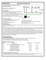
19.2 Model with triac on board and ratiometric pressure trasducer (Pb3)
MF ID1, MF ID2, MF ID5 = multifunction digital inputs
ID3 = high pressure digital input
ID4 = low pressure digital input
RL1 = compressor relay
MF RL2, MF RL3, MF RL4 = multifunction relays
RL5 = output for multifunction external relay
Triac out fan = output for condenser fan
Pb1, Pb2, Pb4 = NTC probe or digital input
Pb3 = ratiometric pressure trasducer
MF o.c. out = multifunction open collector output (for external
relay)

IC100CX
1592022550 Quick reference guide IC100CX GB rel.1.0 03/03/2008 Page 20 di 39
19.3 Model with 5 internal relays and pressure trasducer (Pb3)
MF ID1, MF ID2, MF ID5 = multifunction digital inputs
ID3 = high pressure digital input
ID4 = low pressure digital input
MF RL2, MF RL3, MF RL4, MF RL5 = multifunction relays
Pb1, Pb2, Pb4 = NTC probe or digital input
Pb3 = pressure trasducer
Tk = output for external fan speed controller
MF o.c. out = multifunction open collector output (for
external relay)
19.4 Model with 5 internal relays and ratiometric pressure trasducer (Pb3)
MF ID1, MF ID2, MF ID5 = multifunction digital inputs
ID3 = high pressure digital input
ID4 = low pressure digital input
MF RL2, MF RL3, MF RL4, MF RL5 = multifunction relays
Pb1, Pb2, Pb4 = NTC probe or digital input
Pb3 = ratiometric pressure trasducer
Tk = output for external fan speed controller
MF o.c. out = multifunction open collector output (for external
relay)
/