Vallox X-Line TTXP EC User manual

Type
User manual

Vallox X-Line TTXP EC, your new house extraction fan, offers multiple features to optimize ventilation in your home. It functions as an air extraction unit, removing cooking smells above the cooktop and serving as a general extraction valve in the kitchen. With its ventilation control panel, you can adjust the efficiency based on your needs, including Away mode for reduced ventilation when unoccupied, Normal mode for continuous extraction, and Boost mode for increased ventilation during cooking, sauna use, or excessive heat.

Vallox X-Line TTXP EC, your new house extraction fan, offers multiple features to optimize ventilation in your home. It functions as an air extraction unit, removing cooking smells above the cooktop and serving as a general extraction valve in the kitchen. With its ventilation control panel, you can adjust the efficiency based on your needs, including Away mode for reduced ventilation when unoccupied, Normal mode for continuous extraction, and Boost mode for increased ventilation during cooking, sauna use, or excessive heat.

TTXP EC
Manual
Document
D10999
Valid from
25.03.2022
Updated
02.05.2022
MANUAL
Model
Vallox X-Line TTXP EC
Type
27983-4
Vallox X-Line TTXP EC house extraction fan is suited to use as an air extraction
unit or a cooker hood in apartments.
The house extraction fan serves as the air extraction unit of the apartment,
removes cooking smells from above the cooker top, and serves as a general
extraction valve in the kitchen.
2
TTXP EC
MANUAL
VENTILATION CONTROL
The house extraction fan serves as the mechanical air
extraction unit in the apartment, allowing the resident to
adjust the ventilation eciency. Adjustments are made,
based on the need, via the ventilation control panel.
USING THE UNIT
Position of the damper
When turned to the left, the damper is in the closed
position: In normal circumstances, the damper must be
closed,
which boosts the extract air flow from other premises.
When turned to the right, the damper is in the open
position:
used when the extract air flow needs to be boosted,
e.g., in the following situations:
when the cooker top or the oven is used for cooking
when the load in the kitchen is exceptional e.g. due to
the use of strong detergents or the presence of a large
number of people.
The extraction can be boosted, where required, by using
the ventilation control panel.
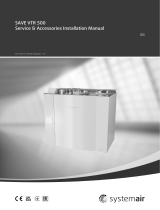
Light switch of the fan
Rocker switch operation
Right side down, light on
Left side down, light o
Front panel
1. Away mode (position 1).
The ventilation eciency can be temporarily reduced
when the apartment is unoccupied.
2. Normal mode (position 2 or 3)
Ventilation must be constant to ensure that impurities
related to normal living are removed from the indoor air.
3. Boost mode (positions 3-4)
Cooking, sauna, bathing, drying of clothes, excessive
heat, and other similar situations can require that
ventilation be increased from the standard setting. In
such a situation, ventilation must be increased. This
is done by boosting the ventilation either in general
or space-specifically. For example, the damper of the
cooker hood is kept open during cooking but is closed
or in the minimum position at other times.
MAINTENANCE
Keep the fan clean. Wipe outer surfaces regularly with water
containing a small amount of a mild detergent. Clean o any
grease stains immediately. Do not use abrasive or corrosive
detergents or tools.
Keep the grease filter clean to ensure an adequate extract air
flow. The grease filter must be washed with warm water and
detergent at least 1-2 times a month.
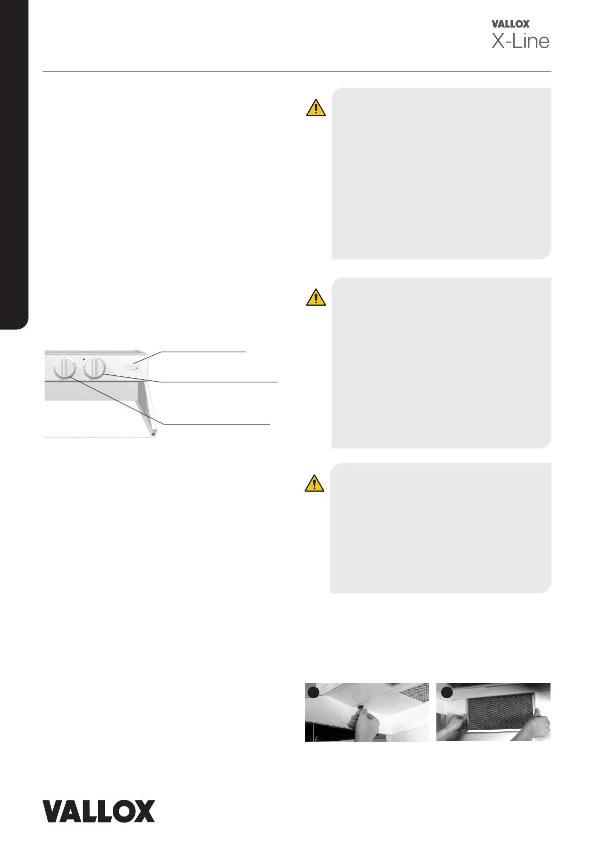
Removing and mounting the grease
filter
Open the quick connectors of the bottom plate of the
cooker hood by turning (figure 1).
Turn the bottom plate down.
Remove the grease filter from its holder (figure 2).
1 2
Light switch
Ventilation control
panel
Fan damper control
panel
CAUTION
Neglecting the cleaning of the grease filter
can cause a fire hazard.
The outer surfaces of the hood can
become hot when the cooker or the oven is
turned on.
Flaming is forbidden underneath the
cooker hood.
Always follow the instructions provided on
adjusting the eciency of ventilation.
Enable a sucient supply air flow into the
room if the cooker hood and non-electric
devices are used simultaneously.
WARNING
If the ventilation of the apartment is turned
o, the entry of fresh replacement air into
the apartment and the extraction of used air
from the apartment are prevented. Impurities,
such as carbon dioxide, humidity, smells,
formaldehyde, dust, and radon, that come from
people, structures, and the soil will quickly
contaminate the room air and are harmful to
the health of people. Excessive humidity may
damage the structures of the building and result
in mould and fungal growth. For this reason,
building regulations require that ventilation be
turned on at all times and that its eciency is
adjusted based on the needs of the user.
WARNING
The unit is not intended for use by children
under 8 or by persons with reduced sensory,
physical or mental capabilities, or whose lack of
knowledge and experience do not ensure safe
operation of the unit. Such persons can use
the unit under supervision, or by following the
instructions of someone who is responsible for
their safety. Do not let children play with the unit
or to clean or maintain it without supervision.
3© Vallox Oy - All rights reserved
TTXP EC
MANUAL
Replacing the lamp
Remove the protective glass of the lamp by moving it to the
left (figure 3).
Remove the lamp by pulling it to the left (figure 4).
Lamp type: G23 LED.
INSTALLATION
Use the mounting accessories included in the package to
fasten the fan in place.
1. Fasten mounting brackets to the rear edge and the
sides of the fan (figure 1).
2. Lift the fan in place and fasten the mounting brackets of
the rear edge to the wall (figure 2). The mounting screws
included in the accessory bag are suited to walls made
of wood, chipboard, cement, and stone. Use appropriate
mounting devices for other materials.
3. Fasten the mounting brackets of the sides to the
cabinets (figure 3).
4. Connect the extract air ducts (suction ducts) to the
outlets located on the sides of the house extraction fan.
If the outlets are not used, leave them plugged. Connect
the blow-out duct to the centremost outlet. Ensure that
the connections are airtight.
5. Plug the house extraction fan into the mains. Ensure
that the plug can be unplugged, where required.
Ensure that the fire resistance rating of the duct network
complies with regulations.
3 4
12
4
min. 500 mm /
650mm
3
Cleaning the fan blade of the fan
The fan of the house extraction fan is located in the fan
enclosure mounted on the smell absorption part behind
the spice cabinet or a similar structure.
Remove the spice cabinet or the similar structure.
Unplug the power cord from the socket.
Unscrew the mounting screws of the fan enclosure.
Remove the motor and the fan blade from the fan.
Clean the fan blade with a brush and a wet cloth.
Wipe the inside of the fan enclosure with a wet cloth.
CAUTION
A G23 PL lamp will cause damage!
CAUTION
The minimum distance of the bottom edge of
the grease filter to an electric cooker is 500
mm, and to a gas cooker 650 mm (figure 4).
CAUTION
The fan must not be connected to a flue
that is used for removing combustion
gases (e.g. from a wood- or gas-burning
fireplace, cooker, or stove).
Regulations on leading extraction air
outdoors must be observed.
Dimensions and
connection outlets
1. Extract air from rooms
to the fan
2. Exhaust air out
14
472
500
311
412
174
92
98
140
184 148
498/598
72
92
Ø124
Ø124
Ø124
1
1
2
TTXP EC
Vallox Oy | Myllykyläntie 9-11 | 32200 LOIMAA | FINLAND
MANUAL
D10999/02.05.2022
Performance values
Adjusting the fan speeds
A low signal voltage is coming to the control panel and,
therefore, the adjustment is made when the fan is turned on.
The adjustment is made by using the four holes
found underneath the knob of the ventilation control
panel (figure 2) one speed at a time, by using the
potentiometer of the speed in question.
The set voltage can be measured from the measurement
points found underneath the knob of the control panel
(markings S and -) by using the DC voltage measuring of
a universal meter. The adjustment range is ~2…9.5 V.
The control voltage (air flow) increases when the
potentiometer is turned to the right. The preset voltages
are 3 V,
Set the ventilation control to
position 1 and remove the
knob by using a screwdriver,
for example
Measure the voltage from
poles – and S, set e.g. speed
1 from potentiometer 1
Measure the voltage from
poles – and S, set speed 2
from potentiometer 2, etc.
There are holes for
adjustments and
measurements underneath
the knob
Replace the knob, set the
ventilation control to the next
speed, and remove the knob
again.
Lastly, measure the voltage of each speed from the
measuring pins and record them in the measurement log. In
e.g. terraced houses, the voltage measurement can be used
to “copy” the measurement made in the first apartment to
other similar apartments.
If the fan is only used as a cooker hood, adjust speed 1 so
that the fan will not be turned on.
1
3
5
2
4
N
L
PE
WT
GN
BN
+
S
-
BN
GN
YE
FAN
Factory settings
1 = 3 V
2 = 5 V
3 = 7 V
4 = 9,5 V
G23 LED
Ventilation control panel
Electrical connection
CAUTION
If the fan is
used as the
ventilation unit
of the apartment,
speed 1 must not
be adjusted so
that the fan does
not start.
5 V, 7 V, and 9.5 V.Please note! Do not set the control
voltage so low that the fan does not stop (approx.
1.5 V).
An example of air flow adjustment:
The standard ventilation is adjusted by using speed 2 and
with the damper closed.
Set the control panel to speed 2 and measure the air
flows from the valves.
If the total air flow is too low, increase the control
voltage from potentiometer 2.
If the total air flow is too high, decrease the control
voltage from potentiometer 2. Do not choke the air flow
unnecessarily by using valves!
Adjust the Away air flows similarly by using speed 1
(potentiometer 1).
Adjust the Boost air flows similarly by using speed 3
(potentiometer 3).
Speed 4 is usually reserved for the maximum speed.
Air flow dm³/s
Pressure Pa
0
50
100
150
200
250
300
350
400
450
500
550
0 10 20 30 40 50 60 70 80 90 100 110 120 130 140 150
One extract air duct in use
3 V
5 V
7 V
9,5 V
Sound power level in the suction duct
(one duct) by octave band Lw, dB
Adjustment position
Adjustment
position (V)
3 5 7 9.5
Frequency
of the
octave
of the
octave
band
Hz
63 59 69 77 82
125 55 66 75 80
250 48 61 70 76
500 42 51 60 66
1000 34 45 52 57
2000 18 31 40 46
4000 16 23 32 38
8000 20 22 32 39
LW, dB 61 72 80 85
LWA , dB (A) 44 56 65 70
Sound pressure level coming through the
envelope of the house extraction fan in the room
in which it is installed (10m² sound absorption)
Adjustment
position (V)
3 5 7 9.5
LpA, dB (A) 33 42 49 55
Sound values have been measured at the measurement points
of the facility curve (L) of the air fl ow graph. The values change
very little when the pressure loss in the ducts is low and the fan
settings remain unchanged. The sound values increase when the
pressure loss in the ducts increase.
SOUND VALUES
  • Page 1 1
  • Page 2 2
  • Page 3 3
  • Page 4 4

Vallox X-Line TTXP EC User manual

Type
User manual

Vallox X-Line TTXP EC, your new house extraction fan, offers multiple features to optimize ventilation in your home. It functions as an air extraction unit, removing cooking smells above the cooktop and serving as a general extraction valve in the kitchen. With its ventilation control panel, you can adjust the efficiency based on your needs, including Away mode for reduced ventilation when unoccupied, Normal mode for continuous extraction, and Boost mode for increased ventilation during cooking, sauna use, or excessive heat.

Ask a question and I''ll find the answer in the document

Finding information in a document is now easier with AI