Page is loading ...

505 SERIES POWER SUPPLY
Installation Guide
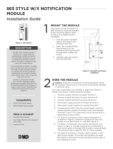
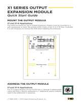
Figure 1: 505 Series Power
Supply
DESCRIPTION
DC
AC TRBL BATT TRBL
BAT
ACAC
1
The DMP 505Series Power Supplies
are regulated, power limited,
switching power supplies. They
are rated for 12VDC at 5Amps
maximum.
Each power supply includes a
transformer, battery leads and is
mounted in an enclosure. The 505
Series power supply also provides
connections for AC input, DC
output, and a standby battery.
Each power supply also includes a
low AC input LED indicator, a low
standby battery LED indicator, AC
trouble and battery trouble relays,
and on‑board transient protection
for the AC input and the DC output.
The 505‑12LX includes two Model
867Style W Notification Modules.
Compatibility
All DMP control panels
What is Included?
• One 505Series PCB Mounted
in Enclosure
• One Wire‑in Transformer
• Battery Leads (One Pair)
• 505‑12LX Only: Two Model 867
NAC Modules
MOUNT THE ENCLOSURE
Mount the power supply metal enclosure in a secure, dry location
to protect the unit from damage due to tampering or the
elements. It is not necessary to remove the PCB or transformer
when installing the enclosure.
Mount Optional NAC Modules
The power supply enclosure can accommodate two NAC modules
for powering various listed notification appliances. Use either the
DMP Model 865 conventional Class A NAC module, the Model 866
conventional Class B NAC module, or the Model 867 LX‑Bus NAC
module. Install any of the modules inside the enclosure using the
3‑hole mounting configuration. Plastic standos are provided with
each module that attach to the enclosure.
To mount a NAC module in a DMP enclosure, complete the
following steps:
1. Mount the plastic standos to the enclosure using the three
included Phillips head screws.
2. Insert the screws through the holes on the enclosure
exterior side and into the plastic standos which mount on
the enclosure inside. Tighten the screws into place and snap
the NAC module onto the standos.
Refer to Figure 2, 3, and 4 for wiring details. Refer to 505 Series
standalone wiring diagrams LT‑0454 and LT‑0849 for specific
wiring applications.
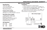
Caution Be sure to observe polarity when connecting wires to
avoid risk of personal injury and equipment damage.
Connect AC Power
Connect the transformer to an unswitched 120VAC 60Hz
power source with at least 1.5Amps of available current. Start by
connecting AC power to the black and white transformer leads,
then connect AC power to the terminal block. Be sure to secure
the green wire lead to an earth ground.
Connect Batteries
Connect the black battery lead to the negative battery terminal
and the red battery lead to the positive battery terminal. Only
use sealed lead‑acid batteries and replace every 3 to 5 years. For
information about calculating standby battery power, refer to
Additional Information.
Connect AC and Battery Trouble Relays
Connect AC TRBL and BATT TRBL supervisory relay outputs
marked NC (normally closed) and C (common) to a control panel
or an 867 NAC zone.
Connect DC Output
Measure and verify output voltage before connecting devices to
ensure proper equipment operation. Connect devices that require
power to output terminals marked ‑ DC +.
WIRE THE 505 SERIES POWER SUPPLY
2

2 505 SERIES POWER SUPPLY INSTALLATION GUIDE | DIGITAL MONITORING PRODUCTS
DC
AC
Trouble
Batt
Trouble
Input:
120 VAC 60
Hz 1.5 Amps
Unswitched
Green
LED
AC
GRAY
VIOLET
Red
LED
DC
RED
Battery
Wires
(included)
AC and battery
output relay
connections
For Access Control
Applications (UL 294)
install a Model 307
Tamper Switch.
Factory
Installed
12 VDC @ 5 Amps
Output:
16 VAC @ 100 VA
Power Limited / Class 2
wire routing through
conduit knockouts
Battery
Start
Ground wire
attached to the
inside of the
enclosure
BLACK
BAT
To 867 NAC
Module
or panel
trouble zone
To panel
tamper zone
To Earth
Ground
BLACK
WHITE
GREEN
Model 505-12
This area fits approximately
two batteries.
To NAC
Optional DMP
Notification
Modules.
Figure 2: 505-12/505-12LX Wiring
NAC Module
(Optional)
This area fits approximately two batteries.
350 or 350A Enclosure
Transformer
Mounting
Hole
NAC Module
(Optional)
Output
16 VDC @ 100 VA
DC
AC
Trouble
Batt
Trouble
Green
LED
AC
Red
LED
DC
RED
Battery
Wires
(included)
AC and battery
output relay
connections
Rated 12 V @ 2
Amps
Factory
Installed
12 VDC @ 5 Amps
Power Limited /
Class 2 wire
routing through
conduit knockouts
Battery
Start
BLACK
BAT
To panel zone
To panel
tamper zone
To NAC (optional)
Model 505-12L/505-12A
Input:
120 VAC 60
Hz 1.5
Amps
Unswitched
Attach ground wire
to an enclosure
mounting hole
BLACK
WHITE
GREEN
GREY
VIOLET
To AC
To Earth
Ground
For Access Control
Applications (UL
294) install a
Model 307 Tamper
Switch.
505-12
Green
LED
AC
Red
LED
DC
Battery
Start
RED
AC
Battery
– +
+ BAT –
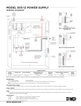
Figure 3: 505-12L/505-12A Wiring
Figure 4: Battery Harness Wiring

3 505 SERIES POWER SUPPLY INSTALLATION GUIDE | DIGITAL MONITORING PRODUCTS
NAC Module Connections
To wire NAC Modules, refer to the 865 Notification Module Installation Sheet (LT‑0179), 866 Notification Module
Installation Sheet (LT‑0059), or 867 Notification Module Installation Sheet (LT‑0178).
Tamper Switch Connection
To connect a tamper switch to a 505 Series enclosure, connect a 2‑pin tamper wire connector from the switch to the
TAMPER header on the panel.
ADDITIONAL INFORMATION
Wiring Specifications
Use 18AWG or larger for all power connections. Ensure there is a minimum 0.25” space to keep power limited wiring
separate from non‑power limited wiring (120VAC/60Hz input, battery wires). Properly ground the power supply before
connecting any devices or applying power to the unit.
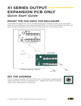
Standby Battery Power Calculations
The following calculation defines the total number of amp‑hours required for standby battery power. After calculating
the total required amp‑hours, install the appropriate number of batteries that slightly exceeds the total. Refer to Table 1.
1. Add the power supply operating current to all other standby current values to obtain the total standby current.
2. Multiply the total standby current by the number of standby hours required to obtain the total standby
milliamp‑hours required.
3. Multiply the total alarm current by 0.25 (0.25 = 15 minute alarm), then add the product to the total standby
milliamp‑hours required to obtain the total required milliamp‑hours.
4. Multiply the total required milliamp‑hours by 0.001 to convert the value to total required amp‑hours.
200 mA Power supply operating current
+ mA Other standby current
= mA Total standby current
x h Number of standby hours required
= mAh Total standby milliamp‑hours required
+ mAh (Total alarm current x 0.25 h)
= mAh Total required milliamp‑hours
x 0.001
= Ah Total required amp‑hours
Table 1: Standby Battery Calculation
AC and Battery Relay Status
Relays are form C with the contacts rated at 30VDC. When an AC trouble or battery trouble occurs, the relay contacts
switch from the NC (normally closed) to the NO (normally open) position. When connected to a panel, an alarm sounds.
When connected to an 867 NAC, the LEDs turn o as listed in Table 2.
Condition Voltage LED Status Condition
AC Trouble
Approx.
102VAC
AC LED
(GRN)
ON AC Good
Battery Trouble
Below
11.8VDC
AC LED
(GRN)
OFF AC Bad
Battery Restoral
Above
12.4VDC
DC LED
(RED)
ON
AC Good,
Battery Good
Battery Cuto
Below
10.2VDC
DC LED
(RED)
OFF
AC Good,
Battery Bad
Table 2: 505 Series LED Operation
NAC Modules Compatibility
The Model 505 Series is compatible with the Wheelock MT‑12/24 Multi‑tone horn at 12VDC.
Power Limited
All circuits on the Model 505 Series comply with the requirements for inherent power limitation and are Class 2 except
the red battery wire.

Designed, engineered, and
manufactured in Springfield, Missouri
using U.S. and global components.
© 2019 Digital Monitoring Products, Inc.
LT-0453 1.04 19314
INTRUSION • FIRE • ACCESS • NETWORKS
2500 North Partnership Boulevard
Springfield, Missouri 65803-8877
800.641.4282 | DMP.com
Certifications
California State Fire Marshal (CSFM)
FCC Part 15
National Fire Protection Association (NFPA)
New York City (FDNY COA #6167)
ANSI/UL 1481 Power Supplies for Fire
Protective Signaling
ANSI/UL 603 Power Supplies for Burglary
Alarm Systems
ANSI/UL 294 Power Supplies for Access
Control System Units
Level I Destructive Attack and Line
Security
Level IV Endurance and Standby
Power
Compatibility
All DMP Control Panels
505-12 POWER SUPPLY
Specifications
Voltage/Current Input
505 Series 120 VAC @ 1.5 Amps max.
Voltage/Current Output
505 Series 12 VDC @ 5 Amps max.
Internal Current Draw 200 mA
Secondary Power Battery
Charge Current 1.5 Amps max.
Enclosure 505-12/505-12LX
Material 20-gauge, cold-rolled steel
Colors Gray (G) or Red (R)
Dimensions 15.75” H x 12.5” W x 4.75” D
Enclosure 505-12L
Material 18-gauge, cold-rolled steel
Colors Gray (G) or Red (R)
Dimensions 17.5” W x 13.5” H x 3.5” D
Enclosure 505-12A
Material 18-gauge with 16-gauge door
Colors Gray (G)
Dimensions 17.5” W x 13.5” H x 3.75” D
DC
AC TRBL BATT TRBL
BAT
ACAC
COMPLIANCE LISTING SPECIFICATIONS
For UL 1481 Power Supplies for Fire Protective Signaling, apply the following maximum battery standby Ampere Hours
to reach 24 hours battery backup.
Battery Standby Maximum 38.5Ah
Output Voltage 12VDC
Output Current 1.25Amp Standby, 5Amp Alarm
Note: A maximum of 38.5Ah is approximately equal to six 7.0Ah Batteries and a maximum of 49.2Ah is
approximately equal to seven 7.0Ah Batteries.
For UL 603 Power Supplies for Burglary Alarm System applications and UL 294 Power Supplies for Access Control
System applications, the 505 Series Power Supply has a voltage range of 10.76V to 12.36V. For UL 294 Access Control
Applications install the Model 307, 307‑S, or 3012 Tamper Switch.
FCC INFORMATION
This device complies with Part 15 of the FCC Rules. Operation is subject to the following two conditions:
1. This device may not cause harmful interference, and
2. This device must accept any interference received, including interference that may cause undesired operation.
The antenna used for this transmitter must be installed to provide a separation distance of at least 20 cm (7.874in.) from
all persons. It must not be located or operated in conjunction with any other antenna or transmitter.
Changes or modifications made by the user and not expressly approved by the party responsible for compliance could
void the user’s authority to operate the equipment.
Note: This equipment has been tested and found to comply with the limits for a Class B digital device, pursuant to
part 15 of the FCC Rules. These limits are designed to provide reasonable protection against harmful interference in
a residential installation. This equipment generates, uses and can radiate radio frequency energy and, if not installed
and used in accordance with the instructions, may cause harmful interference to radio communications. However,
there is no guarantee that interference will not occur in a particular installation. If this equipment does cause
harmful interference to radio or television reception, which can be determined by turning the equipment o and on,
the user is encouraged to try to correct the interference by one or more of the following measures:
• Reorient or relocate the receiving antenna.
• Increase the separation between the equipment and receiver.
• Connect the equipment into an outlet on a circuit dierent from that to which the receiver is connected.
• Consult the dealer or an experienced radio/TV technician for help.
/