Automationdirect.com Productivity 1000 P1-04RTD User manual
- Type
- User manual
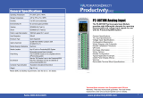
Automationdirect.com Productivity 1000 P1-04RTD helps you receive and process data from analog sensors and devices. You can use it to create a temperature control loop in your oven or other environment. The device has 4 differential input channels and a variety of features:
- Automatic sensor type detection.
- Range selection for each channel.
- Resolution up to 0.1°C or °F.
- Linearization for Pt100, Pt1000, and JPt100 RTD sensors.
- Excitation current of 210µA.
- Burnout detection within 2 seconds.
- Open circuit detection time of 200ms @ 16.7 Hz and 90ms @ 470Hz.


-
 1
1
-
 2
2
-
 3
3
-
 4
4
-
 5
5
-
 6
6
-
 7
7
-
 8
8


Automationdirect.com Productivity 1000 P1-04RTD User manual
- Type
- User manual
Automationdirect.com Productivity 1000 P1-04RTD helps you receive and process data from analog sensors and devices. You can use it to create a temperature control loop in your oven or other environment. The device has 4 differential input channels and a variety of features:
- Automatic sensor type detection.
- Range selection for each channel.
- Resolution up to 0.1°C or °F.
- Linearization for Pt100, Pt1000, and JPt100 RTD sensors.
- Excitation current of 210µA.
- Burnout detection within 2 seconds.
- Open circuit detection time of 200ms @ 16.7 Hz and 90ms @ 470Hz.
Ask a question and I''ll find the answer in the document
Finding information in a document is now easier with AI
Related papers
-
Automationdirect.com Productivity 1000 P1-04DAL-2 User manual
-
-
-
-
-
-
-
-
-
Other documents
-
Multi-Link ZipLink User manual
-
 Automation Direct Productivity2000 P2-08ND3-1 User manual
-
 AutomationDirect StrideLinx Remote Access Solution Operating instructions
-
 Automation Direct PRODUCTIVITY 2000 User manual
-
 Automation Direct SL4848-RR Quick start guide
-
Solo SL4896-RRE Quick start guide
-
 AutomationDirect SL4824 Series Quick start guide
-
 Rockwell Automation Allen-Bradley E300 User manual
-
 AutomationDirect ProSense SC6 Series Quick start guide
-
 AutomationDirect SOLO Basic SLB4848 Series Quick start guide


