Page is loading ...

3505 HUTCHINSON ROAD
CUMMING, GA 30040-5860
Quick Start Guide
Quick Start Guid
e
Quick Start Guid
e
SOLO Temperature Controller
SLB4848 Series
SOLO Basic
Specifications
Selection Guide
Part Number Input Voltage Output #1 Alarm #1* / Output #2** Alarm #2*
SLB4848-R0 100 - 240 VAC Relay - SPST – –
SLB4848-V0 100 - 240 VAC Voltage Pulse – –
SLB4848-C0 100 - 240 VAC Current – –
SLB4848-R2 100 - 240 VAC Relay - SPST Relay - SPST Relay - SPST
SLB4848-V2 100 - 240 VAC Voltage Pulse Relay - SPST Relay - SPST
SLB4848-C2 100 - 240 VAC Current Relay - SPST Relay - SPST
*Alarm #1 and Alarm #2 have a shared common
** Alarm #1 can be configured to function as Alarm #1 or as Control Output #2
3
Controller and Panel Cutout Dimensions
5
This Quick Start Guide provides basic information on setting up the SOLO Basic temperature controller.
For advanced setup visit the AutomationDirect web site at www.AutomationDirect.com.
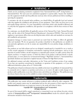
Box Contents and Unpacking Instructions
• Unpack the SOLO Basic temperature controller from its shipping carton. Included in the carton is the tem-
perature controller, mounting bracket plus hardware and this Quick Start Guide.
• Inspect all equipment for completeness. If anything is missing or damaged, immediately call the
AutomationDirect returns department @ 1-800-633-0405.
• Inspect the part number to ensure the model received matches the output type required.
4
Mounting Bracket
and Hardware
SLB4848 Temperature
Controller
SLB4848
Quick Start Guide
Specifications
Input Power Requirements
100 to 240 VAC 50 / 60 Hz
Operation Voltage Range
85 to 264 VAC
Power Consumption
5 VA Max
Control Mode
PID, ON/OFF or Manual
Input Accuracy
TC temperature indication accuracy: ±(0.3% of span + 1 digit) at 25°C ambient after 20 minutes warm up.
Including NIST conformity, cold junction effect, A/D conversion errors and linearization conformity
RTD temperature indication accuracy: ±(0.2% of span +1 digit)
Vibration Resistance
10 to 55 Hz, 10 m/s
2
for 10 min, each in X, Y and Z directions
Shock Resistance
Max. 300 m/s
2
, 3 times in each 3 axes, 6 directions
Ambient Temperature Range
32°F to 122°F (0°C to 50°C)
Storage Temperature Range
-4°F to 149°F (-20°C to 65°C)
Altitude
2000m or less
Relative Humidity
35% to 80% (non-condensing)
IP Rating
IP66: Complete protection against dust and powerful water jets from all directions.
(**inside suitable enclosure)
Agency Approvals
UL, CUL, CE (UL file number E311366)
Pollution Degree
Degree 2 - Normally, only non-conductive pollution occurs.
Temporary conductivity caused by condensation is to be expected.
Input Types
• Thermocouple*
K, J, T, E, N, R, S, B, L, U, TXK (Sampling Rate: 100 ms / per scan)
• Platinum RTD
3-wire Pt100, JPt100 (Sampling Rate: 100 ms / per scan)
• Copper, Nickel RTDs
Cu50, Ni120 (Sampling Rate: 100 ms / per scan)
Control Output Options
• Relay (R)
SPST max. 5A @ 250 VAC resistive load
• Voltage Pulse (V)
DC 12V±15%, output current 40mA Max
• Current (C)
DC 4-20 mA output (sourcing) (Load resistance: Max 600Ω)
Alarm Output Option
(2) SPST relays with shared common, 3A @ 250VAC resistive load
*Note: Use only ungrounded thermocouples.
** No corrosive gases
Safety Information
WARNING! Electric shock danger
1. To prevent electric shock, do not touch the AC terminals while the power is supplied to the controller.
This controller is an open-type temperature controller. Make sure to evaluate any dangerous application in
which a serious human injury or serious property damage may occur.
1. Always use recommended solder-less terminals: Fork terminal with insulation (M3 screw, width is 5.8 mm, hole
diameter 3.2mm). Screw size: M3 x 5 (With square washer). Recommended tightening torque: 0.4 Nm. Applicable
wire: Solid/twisted wire 14AWG to 22AWG.
2. Protect the controller from dust or foreign objects to prevent controller malfunction.
3. Do not modify or disassemble the controller.
4. Do not connect anything to the “Not used” terminals.
5. Make sure all wires are connected correctly.
6. Do not install and/or use the controller in places subject to: (a) Dust or corrosive gases and liquid (b) High humidity
(c) Vibration and shock (d) EMI / RFI (e) high temperature.
7. Turn power off when wiring or changing a temperature sensor.
8. Be sure to use wires that match the thermocouple types when extending or connecting the thermocouple wires.
9. Use wires with correct resistance when extending or connecting a platinum resistance thermometer (RTD).
10. Keep the wire as short as possible when wiring a platinum resistance thermometer (RTD) to the controller and
route power wires as far as possible from load wires to prevent interference and induced noise.
11. This controller is an open-type unit and must be placed in an enclosure away from high temperature, humidity,
dripping water, corrosive materials, airborne dust and electric shock or vibration.
12. Make sure power cables and signals from instruments are all installed properly before energizing the controller,
otherwise serious damage may occur.
13. To prevent electric shock, do not touch the terminals in the controller or try to repair the controller when power
is applied.
14. Use a soft, dry cloth to clean the controller. Do not use acid or alkaline liquids for cleaning.
15. This instrument is not furnished with a power switch or fuse. Therefore, if a fuse or power switch is required,
install the protection close to the instrument. Recommended fuse rating: Rated voltage 250 V, Rated current 1
A. Fuse type: Time-lag fuse
16. Note: This controller does not provide overcurrent protection. Use of this product requires that suitable overcur-
rent protection device(s) must be added to ensure compliance with all relevant electrical standards and codes.
(Rated 250 V, 15 Amps max). A suitable disconnecting device should be provided near the controller in the
end-use installation.
1
WARNING: To minimize the risk of potential safety problems, you should follow all applicable local and
national codes that regulate the installation and operation of your equipment. These codes vary from area to
area and it is your responsibility to determine which codes should be followed, and to verify that the equip-
ment, installation, and operation are in compliance with the latest revision of these codes.
Equipment damage or serious injury to personnel can result from the failure to follow all applicable codes
and standards. We do not guarantee the products described in this publication are suitable for your particular
application, nor do we assume any responsibility for your product design, installation, or operation.
If you have any questions concerning the installation or operation of this equipment, or if you need additional
information, please call us at 1-800-633-0405 or 770-844-4200.
This publication is based on information that was available at the time it was printed. At Automationdirect.
com® we constantly strive to improve our products and services, so we reserve the right to make changes to
the products and/or publications at any time without notice and without obligation. This publication may also
discuss features that may not be available in certain revisions of the product.
Product Support
• For product support, specifications, and installation troubleshooting, a complete
User Manual can be downloaded from the On-line Documentation area of the
AutomationDirect web site.
• For additional technical support and questions, call our Technical Support team
@ 1-800-633-0405 or 770-844-4200..
AutomationDirect’s SOLO Basic is a single loop temperature controller that can control heating or cooling
processes. Depending upon the particular model of controller, the available outputs include relay, voltage pulse
or current. On select models there are two alarm outputs available with nine selectable alarm types. SOLO Basic
controllers have a single control output that can be used for control of a heating or cooling application. Models
with alarm outputs can also be configured to use one of the alarm outputs as a second control output allowing
both heating and cooling control or two stage heating or two stage cooling control. There are three types of
control modes: PID, ON/OFF and Manual. SOLO Basic can accept various types of thermocouple and RTDs.
Other features include:
• Auto Tuning (AT) function with PID control
• 1/16 DIN panel size
• 2 line x 4 character 7-segment LCD display for Process Value (PV): Red color, and Set Point (SV): Green color
• Selectable display decimal point XXX.X or XXXX
• Selectable between °C and °F
• UL, CUL and CE agency approvals
General Description
2
Dimensions
inches [mm]

Reset to Factory Default Instructions
10
All of the following set up instructions are for setting up a controller from the factory defaults. If the
application for a controller needs to be changed, reset the controller to factory default using the following
steps.
1. Press the
•
button until the parameter
loC
appears. Use the
.
button to select
loC1
. Press the
;
button.
2. Press and hold the
;
and
.
buttons simultaneously for three seconds and release.
3. Use the
.
button to change the value on the SV display to
1357
. Press the
;
button.
4. Display will change from
pass
to
pare
. Press
.
button symbol to change value from no to yes and
press
;
button.
5. Display will be fully lit and then controller will reboot.
1. Access the Initial Setup mode by pressing and holding the
;
button for three seconds. In the parameter
inpt
, use the
,
and
.
buttons to select the value that corresponds to the thermocouple or RTD type
that will be attached to the controller. See the table below for specifications. Press the
;
button to save the
selected value. The controller will display the module information splash screen for three seconds and then
return to the main screen.
2. Press the
;
button for three seconds again. Press the
•
button to access the
tpun
parameter. Use
the
,
and
.
buttons to select either
C
for Centigrade or
f
for Fahrenheit display. Press the
;
button
to save the selected value. Press the
;
button again to go to the main screen.
3. Press the
;
button for three seconds again. Press the
•
button repeatedly until the
tp-H
parameter
appears. Use the
,
and
.
buttons to set the maximum value of the operational temperature range. The
SV value cannot exceed the TP-H value. Press the
;
button to save the selected value. Press the
•
button
to access the
tp-l
parameter. Use the
,
and
.
buttons to set the minimum value of the operational
temperature range. The SV value cannot be set lower than the TP-L value. Press the
;
button twice to save
the selected value and return to the controller main screen.
4. Press the
•
button repeatedly until the parameter
sp
appears. Use the
,
and
.
buttons to select
either
0
for a whole degree or
1
for a tenth degree temperature display. If tenth degree is selected the maximum
temperature displayed (PV) will be limited to 999.9. Press the
;
button twice to save the selected value and
return to the controller main screen.
5. If the input temperature from the thermocouple or RTD needs to be adjusted, press the
;
button for less
than 3 seconds. Press the
•
button repeatedly until the parameter
pVof
appears. Use the
,
and
.
buttons to adjust a positive or negative offset to the PV value displayed on the controller. Press the
;
button
twice to save the selected value and return to the controller main screen.
Thermocouple or RTD Input
Thermocouple* Type and Temperature Range
Input Temperature Sensor Type LED Display Temperature Range
Thermocouple TXK type
txk
-238 ~ 1472°F (-150 ~ 800°C)
Thermocouple U type
u
-328 ~ 932°F (-200 ~ 500°C)
Thermocouple L type
l
-328 ~ 1562°F (-200 ~ 850°C)
Thermocouple B type
b
212 ~ 3272°F (100 ~ 1800°C)
Thermocouple S type
s
32 ~ 3092°F (0 ~ 1700°C)
Thermocouple R type
r
32 ~ 3092°F (0 ~ 1700°C)
Thermocouple N type
n
-328 ~ 2372°F (-200 ~ 1300°C)
Thermocouple E type
e
32 ~ 1112°F (0 ~ 600°C)
Thermocouple T type
t
-328 ~ 752°F (-200 ~ 400°C)
Thermocouple J type
j
-148 ~ 2192°F (-100 ~ 1200°C)
Thermocouple K type
k
-328 ~ 2372°F (-200 ~ 1300°C)
RTD Type and Temperature Range
Input Temperature Sensor Type LED Display Temperature Range
Platinum (Pt100)
pt
-328 ~ 1562°F (-200 ~ 850°C)
Platinum (JPt100)
jpt
-148 ~ 752°F (-100 ~ 400°C)
Copper (Cu50)
CU
-58 ~ 302°F (-50 ~ 150°C)
Nickel (Ni120)
ni
-112 ~ 572°F (-80 ~ 300°C)
*Note: Use only ungrounded thermocouples.
11
WARNING! Electric shock danger
To prevent electric shock, do not connect AC power to your device until all input and output
connections are completed.
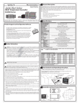
Terminal Identification
7
1
2
3
3
4
55
6
7
8
9
10
11
12
AC 100~240V
50/60 Hz 5VA
L
+
–
+
–
+
–
N
OUT
RTD
Tc
1
2
3
3
4
5
5
6
7
8
9
10
11
12
AC 100~240V
50/60 Hz 5VA
L
+
–
N
3A
250 Vac
OUT1
RTD
ALM1/OUT2
ALM2
COM
Tc
SLB4848-C0
SLB4848-V0
(No alarm output)
(2 sets of alarm outputs)
SLB4848-C2
SLB4848-V2
1
2
3
3
4
55
6
7
8
9
10
11
12
AC 100~240V
50/60 Hz 5VA
L
+
–
+
–
N
RTD
Tc
1
2
3
3
4
5
5
6
7
8
9
10
11
12
AC 100~240V
50/60 Hz 5VA
L
N
OUT1
5A/250 Vac
3A
250 Vac
RTD
ALM1/OUT2
ALM2
COM
Tc
(No alarm output)
(2 sets of alarm outputs)
SLB4848-R0 SLB4848-R2
COM
NO
OUT
5A/250 Vac
NO
COM
Mounting Instructions
SOLO Basic temperature controllers can be mounted through a cutout in an enclosure or panel by using the
dimensions shown in Section 5. The directions for mounting the controller through a cutout are:
1. Insert the temperature controller through the panel cutout.
2. Slide the M3X0.5 nut into the opening in the top of the mounting bracket and insert the M3X0.5 X 30mm
mounting screw in the mounting bracket.
3. Insert the mounting bracket into the mounting groove at the left and right of the controller, and push the
mounting bracket forward until the bracket stops.
4. Tighten both screws evenly to secure temperature controller in place (The screw torque should be 0.4 to 0.5
N-m)
6
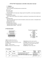
Display and Key Pad
SLB
SOLO
SET
c
SV
PV
A/M
OUT1
1
2
OUT2
PV Display: Display the process value or parameter type.
SV Display: Display the set point, parameter operation, read value,
manipulated variable or set value of the parameter.
A/M: Auto-tuning/Manual indicator, flashes when the Auto-tuning operation is
ON and is solid when in Manual mode.
OUT1/OUT2: Output indicator, lights when the output is ON.
°C, °F: Temperature unit indicator. °C: Celsius °F: Fahrenheit
1/2: Alarm output indicator, lights when one of the alarms is on.
Key Indicator: Key indicator lights when key lock is enabled.
Set Button: Press this key to select the desired function mode and
confirm the setting value.
Rotate Button: Press this key to select parameters within the function
mode.
Down Button: Press this key to decrease values displayed on the SV
display. Hold down this key to speed up the decrement.
Up Button: Press this key to increase values displayed on the SV
display. Hold down this key to speed up the increment.
8
Key Pad Operation
Operation Mode
SET
Hold for 3 sec.
SET
Initial Setting
Mode
Regulation
Mode
SET
Press for less
than 3 sec.
Initial Setting
Parameters
Operation
Parameters
Regulation
Parameters
SET
The SOLO Basic temperature controller has three function modes: Initial Setting mode, Operation mode and
Regulation mode. When power is first applied to the temperature controller, the module information splash
screen appears. This screen shows the firmware version on the PV display and the input and output types for that
particular model on the SV display. After three seconds, the controller will automatically proceed to the Operation
mode main screen. Press and hold the
;
button for three seconds to go into the Initial Setting mode. Press
the
;
button for less than three seconds to access the Regulation mode. Press the
•
button while inside
any of the three function modes to access the individual parameters for each function mode. Use the
.
and
,
buttons to change the individual parameter values. Pressing the
;
button saves the parameter values.
Press the
;
button again to return the controller to the Operation mode.
9

Heating Loop with PID Control
1. Access the Initial Setup mode by pressing and holding the
;
button for three seconds. Press the
•
button repeatedly until the parameter
Ctrl
appears. Confirm the default value
Pid
is selected for PID
control. Press the
•
button to access the parameter
s-hC
. Confirm the default value
h1
is selected for
controlling a heating loop. Press the
;
button to return to the controller main screen.
2. Press the
•
button to access the parameter
r-s
. Verify that the default value
run
is selected. Press
the
;
button to return to the controller main screen.
3. Refer to Section 12-1 of this Quick Start Guide to set up the PID control parameters.
4. If the temperature controller’s output is discrete, access the regulation mode again by pressing the
;
button for less than three seconds. Press the
•
button repeatedly until the parameter
o1-h
appears. Use
the
,
and
.
buttons to set the time period in seconds for the heating control. Press the
;
button twice
to save the value and return to the controller main screen.
12-2
Cooling Loop with ON / OFF Control
1. Access the Initial Setup mode by pressing and holding the
;
button for three seconds. Press the
•
button repeatedly until the parameter
Ctrl
appears. Use the
,
and
.
buttons to select
onof
for ON
/ OFF control. Press the
;
button to save the value. Press the
•
button to access the parameter
s-hC
.
Use the
.
button to select
C1
for controlling a cooling loop. Press the
;
button twice to save the value
and return to the controller main screen.
2. Press the
•
button to access the parameter
r-s
. Verify that the default value
run
is selected. Press
the
;
button to return to the controller main screen.
3. Press the
;
button for less than three seconds to access the parameter
o1-s
. Use the
,
and
.
buttons to enter hysteresis. This is the amount the PV must go above the SV before the controller output turns
on. Press the
;
button twice to save the selected value and return to the controller main screen.
12-5
Heating Loop with ON / OFF Control
1. Access the Initial Setup mode by pressing and holding the
;
button for three seconds. Press the
•
button repeatedly until the parameter
Ctrl
appears. Use the
,
and
.
buttons to select
onof
for ON
/ OFF control. Press the
;
button to save the value. Press the
•
button to access the parameter
s-hC
.
Confirm the default value
h1
is selected for controlling a heating loop. Press the
;
button to return to the
controller main screen.
2. Press the
•
button to access the parameter
r-s
. Verify that the default value
run
is selected. Press
the
;
button to return to the controller main screen.
3. Press the
;
button for less than three seconds to access the parameter
o1-s
. Use the
,
and
.
buttons to enter hysteresis. This is the amount the PV must go below the SV before the controller output turns
on. Press the
;
button twice to save the selected value and return to the controller main screen.
12-3
Cooling Loop with PID Control
1. Access the Initial Setup mode by pressing and holding the
;
button for three seconds. Press the
•
button repeatedly until the parameter
Ctrl
appears. Confirm the default value
Pid
is selected for PID
control. Press the
•
button to access the parameter
s-hC
. Use the
.
button to select
C1
for
controlling a cooling loop. Press the
;
button twice to save the value and return to the controller main screen.
2. Press the
•
button to access the parameter
r-s
. Verify that the default value
run
is selected. Press
the
;
button to return to the controller main screen.
3. Refer to Section 12-1 of this Quick Start Guide to set up the PID control parameters.
4. If the temperature controller’s output is discrete, access the regulation mode again by pressing the
;
button for less than three seconds. Press the
•
button repeatedly until the parameter
o1-C
appears. Use
the
,
and
.
buttons to set the time period in seconds for the cooling control. Press the
;
button twice
to save the value and return to the controller main screen.
12-4
PID Control Setup
The parameters for PID can be auto-tuned using the
At
parameter. Access this parameter by pressing the
;
button for less than three seconds. Use the
.
button to turn the auto-tune feature
on
. Press the
;
button to save the value. Optimal PID values are automatically determined with the auto-tune feature.
PID operation can also be controlled by programming the individual
p
,
i
, and
d
parameters. Access these
parameters by pressing the
;
button for less than three seconds and press the
•
button repeatedly
until the parameter
p
appears. Use the
,
and
.
buttons to change the value for the Proportional band
if desired and press the
;
button to save the value. Press the
•
button to access the
i
parameter. Use
the
,
and
.
buttons to change the value for the Integral time if desired and press the
;
button to
save the value. Press the
•
button to access the
d
parameter. Use the
,
and
.
buttons to change
the value for the Derivative time if desired and press the
;
button twice to save the value and return to the
controller main screen.
12-1
Note: PID options only available when control mode is set to PID.
Use the
,
and
.
buttons to set the desired setoint and press
;
to save before
starting the auto-tune process
Dual Output with PID Control
Only available on the SOLO Basic units with alarms. When used in a dual output mode the output for Alarm 1
is reassigned as Output 2. Output 2 and Alarm 2 will share the same common in this configuration and should
be taken into consideration when planning unit wiring.
1. Access the Initial Setup mode by pressing and holding the
;
button for three seconds. Press the
•
button repeatedly until the parameter
CtrL
appears. Confirm the default value
pid
is selected for PID
control. Press the
•
button to access the parameter
s-hC
. Use the
.
or
,
button to select
h1C2
for controlling a dual heating / cooling loop or
C1H2
a dual cooling / heating loop. The
h1C2
setting will
assign the heating control to Output 1 and the cooling control to Output 2 and
C1H2
will assign the cooling
control to Output 1 and the heating control to Output 2. Press the
;
button twice to save the value and return
to the controller main screen.
2. Press the
•
button to access the parameter
r-s
. Verify that the default value
run
is selected. Press
the
;
button to return to the controller main screen.
3. Refer to Section 12-1 of this Quick Start Guide to set up the PID control parameters.
4. To adjust the control cycle for Output 1 access the regulation mode again by pressing the
;
button for less
than three seconds. Press the
•
button repeatedly until the parameter
o1-H
or
o1-C
appears if heating or cooling is assigned to Output
1. Use the
.
and
,
buttons to set the time period in seconds for
the control cycle of Output 1. Press the
;
button to save the value.
To adjust the control cycle for Output 2 press the
•
button repeatedly
until the parameter
o2-H
or
o2-C
appears if heating or cooling is
assigned to Output 2. Use the
.
and
,
buttons to enter the cycle
period in seconds for Output 2. Press the
;
button twice to save the
value and return to the controller main screen.
5.Optional regulation parameters can be programmed for dual output
control. If this is desired, access the regulation mode again by pressing
the
;
button for less than three seconds. Press the
•
button repeat-
edly until the parameter
Coef
appears. This value allows the control
selected for Output 2 to have a different proportional setting than the
control selected for Output 1. The Output 1 proportional band setting is
multiplied by the
Coef
value to create a proportional band setting for
Output 2. Use the
.
and
,
buttons to change this value if desired. Press the
;
button to save the
selected value. Press the
•
button to access the parameter
dead
. Use the
.
and
,
buttons to enter
a deadband zone value around the setpoint where the output is not affected by the proportional control value. If
the PV remains within the deadband zone the output is not affected by the proportional control. The integral and
derivative controls ignore the deadband setting and may cause the output to be on within the deadband zone.
Press the
;
button twice to save the value and return to the controller main screen.
12-7
PV
0
Output
Dead band: dead
band width=positive
Set point
HeatingCooling
dead
PV
0
Output
Dead band: dead
band width=negati
ve
Set point
Heating
Cooling
dead
Dual control with PID
positive deadband
Dual control with PID
negative deadband
Dual Output with ON / OFF Control
Only available on the SOLO Basic units with alarms. When used in a dual output mode the output for Alarm 1
is reassigned as Output 2. Output 2 and Alarm 2 will share the same common in this configuration and should
be taken into consideration when planning unit wiring.
1. Access the Initial Setup mode by pressing and holding the
;
button for three seconds. Press the
•
button repeatedly until the parameter
CtrL
appears. Use the
.
and
,
buttons to select
onof
for
ON / OFF control and press the
;
button to save the selected value. Press the
•
button to access the
parameter
s-hC
. Use the
.
and
,
buttons to select
H1C2
for controlling a dual heating / cooling loop
or
C1h2
a dual cooling / heating loop. The
H1C2
setting will assign the heating control to Output 1 and the
cooling control to Output 2 and
C1h2
will assign the cooling control
to Output 1 and the heating control to Output 2. Press the
;
button
twice to save the value and return to the controller main screen.
2. Press the
•
button to access the parameter
r-s
. Verify that
the default value
run
is selected. Press the
;
button to return
to the controller main screen.
3. Press the
;
button for less than three seconds to access the
parameter
o1-S
. Use the
.
and
,
buttons to enter hyster-
esis for Output 1, the heating control in the example diagram. This is the
amount the PV must go below, or above if Output 1 is setup for cooling, the SV before the controller output turns
on. Press the
;
button to save the selected value. Press the
•
button to access the parameter
o2-S
.
Use the
.
and
,
buttons to enter hysteresis for Output 2, the cooling control in the example diagram.
This is the amount the PV must go above, or below if Output 2 is setup for heating, the SV before the controller
output turns on. Press the
;
button twice to save the selected value and return to the controller main screen.
4. Optional regulation parameters can be programmed for additional dual loop control. If this is desired, access
the regulation mode again by pressing the
;
button for less than three seconds. Press the
•
button
repeatedly until the parameter
dead
appears. Use the
.
and
,
buttons to enter a deadband zone
value around the setpoint where the output is not on. The PV must go beyond the deadband range for either
the heating or cooling output to turn on. Press the
;
button twice to save the selected value and return to
the controller main screen.
12-8
OFF
PV
Set point
ON
Heating
Dead band
Output 1 Hysteresis
Output 2 Hysteresis
Cooling
o1-s 02-s
dead
Dual loop ON / OFF control
output operation
Manual Control
1. Access the Initial Setup mode by pressing and holding the
;
button for three seconds. Press the
•
button repeatedly until the parameter
Ctrl
appears. Use the
,
and
.
buttons to select
manu
for
manual control. Press the
;
button twice to save the selected value and return to the controller main screen.
2. Press the
•
button to access the parameter
out1
. Use the
,
and
.
buttons to set a value
between
)0
and
10)0
to control output directly. If the controller has a discrete output, a value of
2)0
turns the output on 20% of the time. A value of
10)0
would turn the output on 100% of the time. A manually
controlled analog output value is a percentage of the analog signal. For example, if the controller has a 4-20mA
current output, a setting of
)0
would mean that the output would be 4mA. The output would be 20mA with a
setting of
10)0
. Press the
;
button to save the selected value. The same process can be followed for
out2
on units with alarms configured for dual output. Refer to Section 12-7 or 12-8.
12-6
Control Setup
Please choose the desired control mode and follow the instructions in that section. For example, to control
heat in an oven, the Heating Loop with PID Control could be used by following the steps in 12-2. For a cooling
operation like a freezer one could use Cooling Loop with ON / OFF Control in section 12-5.
To change the control mode, it is recommended to do a factory reset before setting up the new control mode.
Please see section 10 of this document for instructions on how to complete a reset to factory defaults.
12

Error Display Information
14
The chart below shows the possible error displays on the Solo Basic temperature controller.
Controller Error Display
Display Position Display Meaning
Cause
Corrective Action
PV
no
Cont
No sensor input
The input terminals
are open.
Check the input wiring. If the problem still exists, replace the
sensor or the controller.
SV
PV
sen
err
Sensor type error
Temperature is out of
range for sensor type
Check sensor type and its condition. If damaged or wrong,
replace and update settings. Check actual condition to make
sure temperature is within sensor range.
SV
Alarm Outputs
For models equipped with alarms there are two alarm outputs. Each alarm can be programmed for one of nine
different alarm types. To set up the first alarm output, press the
;
button for three seconds. Press the
•
button repeatedly until the parameter
ALA1
appears. If the controller is configured for dual output control,
parameter
ALA1
is not available. Use the
.
button to choose the set value for the desired alarm type. Refer
to the chart below for alarm type information. Press the
;
button to save the selected value. If additional
alarm outputs are required press the
•
button to proceed to
ALA2
. Follow the same procedure to program
the additional alarm. When the desired alarm(s) are programmed, press the
;
button repeatedly until the
controller returns to the main screen.
The alarm output limits are controlled by the parameters
Al
n
h
and
Al
n
l
, where “n” corresponds to the
alarm output chosen. After selecting the desired alarm, press the
•
button repeatedly until the parameter
Al
n
h
and/or
Al
n
l
appears. Use the
.
and
,
buttons to enter the high and/or low values for each
alarm outputs selected. Press the
;
button to save each selected value. Press the
;
button again to
return to the controller main screen.
For advanced alarm options
Al1o
/
al2o
and alarm delay
al1d
/
al2d
please reference the parameter
descriptions in chapter 3 of the user manual.
ALA1
and
ALA2
are both SPST resistive load 3A @ 250 VAC, normally open relay outputs with a shared
common.
13
Set Value Alarm Type Alarm Output Operation
0 Alarm function disabled
Output is OFF
1
Deviation upper- and lower-limit:
Alarm output activates when PV value is higher than the setting value SV+(AL-H) or
lower than the setting value SV-(AL-L).
ON
OFF
SV-(AL-L)
SV
SV+(AL-H)
2
Deviation upper limit:
Alarm output activates when PV value is higher than the setting value SV+(AL-H).
ON
OFF
SV SV+(AL-H
)
3
Deviation lower limit:
Alarm output activates when PV value is lower than the setting value SV-(AL-L).
ON
OF
F
SV-(AL-L)
SV
4
Absolute value upper and lower limit:
Alarm output activates when PV value is higher than the setting value AL-H or lower
than the setting value AL-L.
ON
OFF
AL-L AL-H
5
Absolute value upper limit:
Alarm output activates when PV value is higher than the setting value AL-H.
ON
OFF
AL-H
6
Absolute value lower limit:
Alarm output activates when PV value is lower than the setting value AL-L.
ON
OFF
AL-L
7
Hysteresis upper limit alarm output:
Alarm output activates when PV value is higher than the setting value SV+(AL-H). The
alarm output turns OFF when the PV value is lower than the setting value SV+(AL-L).
ON
OFF
SV SV+(AL-L) SV+(AL-H)
8
Hysteresis lower limit alarm output:
Alarm output activates when PV value is lower than the setting value SV-(AL-H). The
alarm output turns OFF when the PV value is higher than the setting value SV-(AL-L).
ON
OFF
SV-(AL-H) SV-(AL-L) SV
9
Disconnection Alarm: This alarm output is enabled if the sensor connection is
incorrect or has been disconnected.
Parameter Default Settings
15
Parameter Default Settings
Display Description Default Setting
1234
Use
.
or
,
to set temperature set point. Press
•
to switch digits and
;
to set value.
r-S
RUN/STOP: Control setting RUN/STOP RUN
SP
SELECT POINT: Decimal point setting (0: integer; 1: one decimal point) 0
LoC
LOCK: Setting lock mode (LOCK1: all; LOCK2: only SV changes are allowed) OFF
AL1H
ALARM1 HIGH: Upper limit alarm 1 (display according to the setting in ALARM mode)
4.0
AL1L
ALARM1 LOW: Lower limit alarm 1 (display according to the setting in ALARM mode)
4.0
AL2H
ALARM2 HIGH: Upper limit alarm 2 (display according to the setting in ALARM mode)
4.0
AL2L
ALARM2 LOW: Lower limit alarm 2 (display according to the setting in ALARM mode)
4.0
out1
OUT1: Display and adjust output value of 1st output group
0.0
out2
OUT2: Display and adjust output value of 2nd output group (display when
s-hC
is set to a dual
output mode)
0.0
o1ma
OUT1 MAX.: Upper limit % of 1st output group
100.0
o1mC
OUT1 MIN.: Lower limit % of 1st output group
0.0
o2mA
OUT2 MAX: Upper limit % of 2nd output group (display when
s-hC
is set to a dual output mode)
100.0
o2mi
OUT2 MIN: Lower limit % of 2nd output group (display when
s-hC
is set to a dual output mode)
0.0
inpt
INPUT: Set input type (refer to section 11 for a list of supported temperature sensors)
K
tpun
TEMP. UNIT: Set temperature unit C/F
C
tp-h
"TEMP. HIGH: Set up upper temperature limit
(the upper limit setting is different for different types of sensors)"
1300
tp-l
"TEMP. LOW: Set up lower temperature limit
(the lower limit setting is different for different types of sensors)"
-200
Ctrl
CONTROL: Select control modes (3 different modes: ON-OFF, PID, and MANUAL)
PID
S-HC
SELECT HEAT/COOL: Select heating, cooling or dual-output heating and cooling.
H1
ALA1
ALARM1 SET: Set up Alarm 1 mode (refer to section 13 "Alarm Outputs")
0
Al1o
ALARM1 OPTION: Set up Alarm 1 options
0
al1d
ALARM1 DELAY: Set up Alarm 1 delay
0
ala2
ALARM2 SET: Set up Alarm 2 mode (refer to section 13 "Alarm Outputs")
0
al2o
ALARM2 OPTION: Set up Alarm 2 options
0
al2d
ALARM2 DELAY: Set up Alarm 2 delay
0
at
AT: Auto tuning (display when setting
Ctrl
= PID/RUN)
OFF
p
P: Proportional Band (display when setting
Ctrl
= PID automatically set after auto tuning)
30.0
i
I: Integral Time (display when setting
Ctrl
= PID automatically set after auto tuning)
120
d
D: Deviation Time (display when setting
Ctrl
= PID automatically set after auto tuning)
30
pdof
PD OFFSET: PD offset when Integral = 0 to eliminate a consistent deviation (display when setting
Ctrl
= PID automatically set after auto tuning)
50.0
o1-s
OUT1 HYSTERESIS: Adjust Output 1 hysteresis (when
Ctrl
= ON/OFF)
0
o2-s
OUT2 HYSTERESIS: Adjust Output 2 hysteresis (when
Ctrl
= ON/OFF)
0
o1-h
OUT1 HEAT: Heating control cycle for Output 1 (when
Ctrl
= PID/MANUAL)
Output type:
C: 1 sec
V: 5 sec
R: 20 sec
o1-C
OUT1 COOL: Cooling control cycle for Output 1 (when
Ctrl
= PID/MANUAL)
o2-h
OUT2 HEAT: Heating control cycle for Output 2 (when
Ctrl
= PID/MANUAL)
o2-C
OUT2 COOL: Cooling control cycle for Output 2 (when
Ctrl
= PID/MANUAL)
Coef
COEF: Proportional band coefficient of Output 1 against Output 2 (when
Ctrl
= PID and when
in dual output control)
1.00
dead
DEAD: Set up deadband (when
Ctrl
is not set to MANUAL and when in dual output)
0
pv-f
PV FILTER: Set up input filter factor of PV
2
pv-r
PV RANGE: Set up input filter range of PV
1.00
pvof
PV OFFSET: Adjust input compensation of PV
0
pv6a
PV GAIN: Adjust input gain of PV
0.000
a1ma
ANALOG OUT1 MAX.: Adjust upper limit compensation for analog Output 1 (1 scale = 1 μA)
0
a1mi
ANALOG OUT1 MIN.: Adjust lower limit compensation for analog Output 1 (1 scale = 1 μA)
0
Notes:
/