Page is loading ...

MB879
Intel Pentium
®
M
ATI Radeon Xpress 200
Mini-ITX Motherboard
USER’S MANUAL
Version 1.0

ii
MB879 User’s Manual
Acknowledgments
Award is a registered trademark of Award Software International,
Inc.
PS/2 is a trademark of International Business Machines
Corporation.
Intel and Pentium M are registered trademarks of Intel
Corporation.
Microsoft Windows is a registered trademark of Microsoft
Corporation.
Winbond is a registered trademark of Winbond Electronics
Corporation.
All other product names or trademarks are properties of their
respective owners.

MB879 User’s Manual iii
Table of Contents
Introduction.......................................................1
Product Description.............................................................1
Checklist..............................................................................2
MB879 Specifications.........................................................3
Board Dimensions...............................................................4
Installations.......................................................5
Installing the CPU...............................................................6
Installing the Memory.........................................................7
Setting the Jumpers .............................................................8
Connectors on MB879 ......................................................12
BIOS Setup.......................................................23
Drivers Installation......................................47
Intel Chipset Software Installation Utility.........................48
VGA Drivers Installation ..................................................49
LAN Drivers Installation...................................................50
Appendix...........................................................51
A. I/O Port Address Map...................................................51
B. Interrupt Request Lines (IRQ)......................................52
C. Watchdog Timer Configuration....................................53

iv
MB879 User’s Manual
THE MB879 MINI ITX MOTHERBOARD

INTRODUCTION
MB879 User’s Manual 1
Introduction
Product Description
Designed for gaming and multimedia applications, the MB879 Mini ITX board
incorporates the ATi Xpress 200 chipset, supporting CPU front side bus of
400MHzz and 533MHz. The board accommodates Pentium® M and Celeron®
M processors with speeds up to 2.26GHz and one DDR2 DIMM memory.
The MB879 comes with the RC410MD Integrated Graphics Processor (IGP) that
integrates 2D/3D graphics and a system controller in a single chip. The
RC410MB delivers the best performance of all integrated graphics and core
logic products in the market. It incorporates an ATI Radeon X300-based
graphics core, which is coupled with 64-bit DDR/DDR2 SDRAM system
memory interface for optimal performance.
The main features of the board are:
Supports Pentium® M / Celeron® M processors
Supports up to 2.26GHz, 400MHz/533MHz FSB
One DDR2 SDRAM DIMM, Max. 1GB memory
Onboard 10/100 BaseT and Gigabit LAN (MB879F)
ATi Mobility Radeon 9600 VGA for CRT / TV out / LVDS
2x SATA, 6x USB 2.0, 4x COM, Watchdog timer, 1394
1x PCI, 1x MiniPCI, 1xPCI-E(x1) slots
Dimensions of the board are 170mm x 170mm.

INTRODUCTION
2
MB879 User’s Manual
Checklist
Your MB879 package should include the items listed below.
• The MB879 Pentium
®
M Mini-ITX motherboard
• This User’s Manual
• 1 CD containing chipset drivers and flash memory utility

INTRODUCTION
MB879 User’s Manual 3
MB879 Specifications
[
CPU Socket
Socket 479 or FBGA on board
CPU Supported
Intel Pentium® M / Celeron® M (Dothan core only)
CPU Voltage
0.700V ~ 1.708V
CPU Speed / FSB
Up to 2.26GHz / 533MHz FSB
Green /APM
APM1.2
Chipset
ATI Radeon Xpress 200 (RC410MD) / SB450 chipset
NB: ATi Radeon Xpress 200 (RC410MD), 707-ball FCBGA
SB: ATi SB450, 564-ball BGA
BIOS
Award BIOS, support ACPI function
Cache
128K/256K/512K/1M Level 2 (CPU integrated)
Memory
1x DDR2 400/533/667 socket (single channel, w/o ECC),
Max.1GB
VGA
ATi RC410MD built Mobility Radeon 9600 (M10) graphic core.
Supports DirectX 9.0 and supports CRT, LVDS & TV-out
LVDS
ATi RC410MD built controller and transmitter, supports 24-bit
single/dual channels LVDS
LAN
- Realtek RTL8100C-LF (10/100) LAN controller x1 co-layout w/
RTL8110S-32-LF Gigabit LAN controller
- Marvell 88E8052 PCI Express x1 Gigabit LAN controller
(option)
USB
ATi SB450 built-in USB2.0 host controller, supports 6 ports
Audio
ATi SB450 built-in Audio controller + AC97 Codec ALC655 for 5.1
CH (Line-out, Line-in & Microphone)
NS LM4950 (8-ohm 2W stereo audio power amplifier)
Serial ATA
ATi SB450 built-in SATA host controller, supports 2 ports
1394
TI TSB43LV22 (dual port)
Local bus IDE
ATi SB450 built-in two channels Ultra DMA 100/133
- IDE1: 40 pins box-header; IDE2: Compact Flash
LPC I/O
ITE IT8712: COM1, COM2 (RS232), IrDA, Floppy, hardware
monitor (3 thermal inputs, 4 voltage monitor inputs, VID0-5 & 2
Fan Header). Parallel port not use
2
nd
I/O
Fintek F81216D for COM3 / COM4
Edge Connector
(same I/O shield w/
MB896)
PS/2 Connector x1 for keyboard/mouse
Gigabit LAN RJ-45 + dual USB stack connector
10/100 LAN RJ45 + dual USB stack connector
DB9 & DB15 stack connector x1 for COM 1 and VGA
RCA Jack x1 +S-Video for TV-Out
SPDIF/OUT connector x1
1394 Connector x1
RCA Jack 3x1 for Audio (Line-Out, Line-In & Mic) – 1U height
Onboard Headers /
Connectors
DF13-20 x2 for LVDS
40 pins, 2.54mm, box-header x 1 for IDE1
5x2 pins pin-header x1 for 2 USB ports
8 pins pin-header x1 for 1394
30 pins pin-header x1 for COM2/3/4
Slim Floppy connector x 1
5 pins pin-header x 1 for IrDA
Expansion Slot
PCI slot (32bits/33MHz) x1
PCI-Express (x1) x1 (align w/ PCI slot); Mini PCI connector x1
Digital I/O
Supports 4 in, 4 out
Watchdog Timer
Yes (256 segments, 0, 1, 2…255. sec/min)
Power Connector
Standard ATX 12V
System Voltage
+5V, +12V, -12V, 5VSB, -5V & 3.3V
Other Features
Modem Wakeup, LAN Wakeup
Board Size
170 x 170mm

INTRODUCTION
4
MB879 User’s Manual
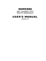
Board Dimensions

INSTALLATIONS
MB879 User’s Manual 5
Installations
This section provides information on how to use the jumpers and
connectors on the MB879 in order to set up a workable system. The
topics covered are:
Installing the CPU ................................................................................. 6
Installing the Memory ........................................................................... 7
Setting the Jumpers................................................................................ 8
Connectors on MB879......................................................................... 12

INSTALLATIONS
6
MB879 User’s Manual
Installing the CPU
The MB879 board supports a Socket 479 processor socket for Intel
®
Pentium
®
M or Celeron
®
M processors.
The processor socket comes with a screw to secure the processor. As
shown in the left picture below, loosen the screw first before inserting
the processor. Place the processor into the socket by making sure the
notch on the corner of the CPU corresponds with the notch on the inside
of the socket. Once the processor has slide into the socket, fasten the
screw. Refer to the figures below.
NOTE:
Ensure that the CPU heat sink and the CPU top surface are in
total contact to avoid CPU overheating problem that would
cause your system to hang or be unstable.

INSTALLATIONS
MB879 User’s Manual 7
Installing the Memory
The MB879 board supports one DDR2 memory socket for a maximum
total memory of 1GB in DDR2 memory type.
Installing and Removing Memory Modules
To install the DDR2 modules, locate the memory slot on the board and
perform the following steps:
1. Hold the DDR2 module so that the key of the DDR2 module align
with those on the memory slot.
2. Gently push the DDR2 module in an upright position until the clips of
the slot close to hold the DDR2 module in place when the DDR2
module touches the bottom of the slot.
3. To remove the DDR2 module, press the clips with both hands.
DDR2 Module
Lock Lock
Lock Lock

INSTALLATIONS
8
MB879 User’s Manual
Setting the Jumpers
Jumpers are used on MB879 to select various settings and features
according to your needs and applications. Contact your supplier if you
have doubts about the best configuration for your needs. The following
lists the connectors on MB879 and their respective functions.
Jumper Locations on MB879..........................................................9
JP1: COM4 RS232 +5V / +12V Power Setting............................10
JP2: LVDS Panel Voltage Selection.............................................10
JP3: COM3 RS232 +5V / +12V Power Setting............................10
JP4: CPU FSB Selection...............................................................10
JP5: Clear CMOS Setting.............................................................11
SW1: LVDS Resolution Switch Setting.......................................11
IMPORTANT NOTE: When the system boots without the CRT being
connected, there will be no image on screen when you insert the
CRT/VGA cable. To show the image on screen, the hotkey must be
pressed.

INSTALLATIONS
MB879 User’s Manual 9
Jumper Locations on MB879
Jumpers on MB879...........................................................................Page
JP1: COM4 RS232 +5V / +12V Power Setting ........................... 10
JP2: LVDS Panel Voltage Selection ............................................ 10
JP3: COM3 RS232 +5V / +12V Power Setting ........................... 10
JP4: CPU FSB Selection .............................................................. 10
JP5: Clear CMOS Setting............................................................. 11
SW1: LVDS Resolution Switch Setting....................................... 11

INSTALLATIONS
10
MB879 User’s Manual
JP1: COM4 RS232 +5V / +12V Power Setting
Pin #
Signal Name JP1 Signal Name
Pin #
1 RI +12V 2
3 RI (Default) RI (Default) 4
5 RI
+5V 6
COM4 Settings: Pin 1-2 short = +12V, Pin 6-5 short = +5V, Pin 3-4
Standard COM Port
JP2: LVDS Panel Voltage Selection
JP2 LVDS Voltage
3.3V
5V
JP3: COM3 RS232 +5V / +12V Power Setting
Pin #
Signal Name JP3 Signal Name
Pin #
1 RI +12V 2
3 RI (Default) RI (Default) 4
5 RI
+5V 6
COM3 Settings: Pin 1-2 short = +12V, Pin 5-6 short = +5V, Pin 3-4
Standard COM Port
JP4: CPU FSB Selection
JP4 CPU FSB
400MHz
533MHz

INSTALLATIONS
MB879 User’s Manual 11
JP5: Clear CMOS Setting
JP5 Setting
Normal
Clear CMOS
[
SW1: LVDS Resolution Switch Setting
SW1-1 SW1-2 SW1-3 SW1-4 Resolution
OFF ON ON ON 800x600
ON OFF ON ON 1024x768
OFF OFF ON ON 1280 X 1024
ON ON OFF ON 1400 X 1050

INSTALLATIONS
12
MB879 User’s Manual
Connectors on MB879
The connectors on MB879 allows you to connect external devices such
as keyboard, floppy disk drives, hard disk drives, etc. The following
table lists the connectors on MB879 and their respective functions.
Connector Locations on MB879...................................................13
CN1: PS/2 Keyboard and PS/2 Mouse Connectors......................14
CN2: S-Video and RCA Connector for TV out............................14
CN3: COM1 and VGA Connector ...............................................14
CN4: 10/100 LAN RJ-45 and USB1/2 Ports................................15
CN5: 1394 Connector...................................................................15
CN6: SPDIF Out Connector.........................................................15
CN7: Gigabit LAN RJ-45 and USB3/4 Ports...............................15
CN8: Audio Connector.................................................................15
FAN1: CPU Fan Power Connector...............................................15
FAN2: System Fan Power Connector...........................................15
J1: Floppy Drive Connector..........................................................16
IDE1: IDE Connector...................................................................16
J2: ATX Power Supply Connector...............................................17
J3: TV Out Header (RCA & S-Video) .........................................17
J4: COM2, COM3, COM4 Serial Ports........................................17
J5: IrDA Connector ......................................................................18
J9, J6: LVDS Connectors (1st channel, 2nd channel) ..................18
J7: Panel Inverter Power Connector .............................................18
J8: Digital I/O...............................................................................18
J10: 1394 Connector.....................................................................19
J11: Panel Inverter Power Connector ...........................................19
J12: Mini PCI Connector..............................................................19
J13: Speaker Connector................................................................19
J14: Front Audio Connector .........................................................19
J15, J16: Serial ATA Connectors .................................................20
J17: Wake On LAN Connector.....................................................20
J18: System Function Connector..................................................20
J19: USB4 / USB5 Connector ......................................................20
J20: CD-In Pin Header .................................................................21
J21: Power LED Connector..........................................................21
J22: Compact Flash Connector (solder side)................................21
PCI1: PCI Slot (supports 2 Masters) ............................................21
PCIE1: PCI-E(x1) Slot .................................................................21

INSTALLATIONS
MB879 User’s Manual 13
Connector Locations on MB879

INSTALLATIONS
14
MB879 User’s Manual
CN1: PS/2 Keyboard and PS/2 Mouse Connectors
PS/2 Mouse
PS/2 Keyboard
Signal Name Keyboard Mouse Signal Name
Keyboard data 1 1 Mouse data
N.C. 2 2 N.C.
GND 3 3 GND
5V 4 4 5V
Keyboard clock 5 5 Mouse clock
N.C. 6 6 N.C.
CN2: S-Video and RCA Connector for TV out
CN3: COM1 and VGA Connector
[
Signal Name Pin # Pin # Signal Name
DCD 1 6 DSR
RXD 2 7 RTS
TXD 3 8 CTS
DTR 4 9 RI
GND 5 10 Not Used
[[[[
Signal Name Pin # Pin # Signal Name
Red 1 2 Green
Blue 3 4 N.C.
GND 5 6 GND
GND 7 8 GND
N.C. 9 10 GND
N.C. 11 12 N.C.
HSYNC 13 14 VSYNC
NC 15

INSTALLATIONS
MB879 User’s Manual 15
CN4: 10/100 LAN RJ-45 and USB1/2 Ports
CN5: 1394 Connector
CN6: SPDIF Out Connector
CN7: Gigabit LAN RJ-45 and USB3/4 Ports
CN8: Audio Connector
The audio connector, from top to bottom, is composed of Line in, Line
out and Microphone jacks.
FAN1: CPU Fan Power Connector
FAN1 is a 3-pin header for the CPU fan. The fan must be a 12V fan.
Pin # Signal Name
1 Ground
2 +12V
3 Rotation detection
FAN2: System Fan Power Connector
FAN2 is a 3-pin header for system fans. The fan must be a 12V (500mA)
fan.
Pin # Signal Name
1 Ground
2 +12V
3 Rotation detection

INSTALLATIONS
16
MB879 User’s Manual
J1: Floppy Drive Connector
J1 is a slim 26-pin connector and will support up to 2.88MB FDD.
Signal Name Pin # Pin # Signal Name
VCC 1 2 INDEX
VCC 3 4 DRV_SEL
VCC 5 6 DSK_CH
NC 7 8 NC
NC 9 10 MOTOR
DINST 11 12 DIR
NC 13 14 STEP
GND 15 16 WDATA
GND 17 18 WGATE
GND 19 20 TRACK
NC 21 22 WPROT
GND 23 24 RDATA
GND 25 26 SIDE
IDE1: IDE Connector
Signal Name Pin # Pin # Signal Name
Reset IDE 1 2 Ground
Host data 7 3 4 Host data 8
Host data 6 5 6 Host data 9
Host data 5 7 8 Host data 10
Host data 4 9 10 Host data 11
Host data 3 11 12 Host data 12
Host data 2 13 14 Host data 13
Host data 1 15 16 Host data 14
Host data 0 17 18 Host data 15
Ground 19 20 Protect pin
DRQ0 21 22 Ground
Host IOW 23 24 Ground
Host IOR 25 26 Ground
IOCHRDY 27 28 Host ALE
DACK0 29 30 Ground
IRQ14 31 32 No connect
Address 1 33 34 No connect
Address 0 35 36 Address 2
Chip select 0 37 38 Chip select 1
Activity 39 40 Ground
/