Safety Rules & General Information
Owner’s Manual for 60 Hz EcoGen™ Generators 1
Section 1: Safety Rules & General Information
Introduction
Thank you for purchasing this compact, high
performance, air-cooled, engine-driven generator. It is
designed to automatically supply electrical power to
operate critical loads during a normal power source
failure.
As supplied from the factory, this generator is designed to
work in off-grid applications.
In off-grid applications as a part of an alternative energy
system, the generator starts when the inverter/battery
charger detects the normal power source voltage has
dropped below a preset level. The generator powers the
inverter, and once the voltage level of the normal power
source rises to an acceptable level, the generator is shut
down. Another off-grid application would be for use in
remote locations such as for pumping water for a village
or campground, or for livestock.
The unit is factory installed in an all-weather metal
enclosure and is intended for outdoor installation only.
The generator can be operated using either natural gas
(NG) or vapor withdrawn liquid propane (LP).
NOTE: When sized properly, this generator is suitable for
supplying typical residential loads such as induction
motors (sump pumps, refrigerators, air conditioners,
furnaces, etc.), electronic components (computer,
monitor, TV, etc.), lighting loads and microwaves, or
loads less than 10 kW or 2 hp.
The information in this manual is accurate based on
products produced at the time of publication. The
manufacturer reserves the right to make technical
updates, corrections, and product revisions at any time
without notice.
Read This Manual Thoroughly
If any portion of this manual is not understood, contact
the nearest Independent Authorized Service Dealer
(IASD) for starting, operating, and servicing procedures.
This manual must be used in conjunction with the
appropriate installation manual.
SAVE THESE INSTRUCTIONS: The manufacturer
suggests that this manual and the rules for safe operation
be copied and posted near the unit installation site.
Safety should be stressed to all operators and potential
operators of this equipment.
Safety Alerts
Throughout this publication and on tags and decals
affixed to the generator, DANGER, WARNING, and
CAUTION blocks are used to alert personnel to special
instructions about a particular operation that may be
hazardous if performed incorrectly or carelessly. Observe
them carefully. Their definitions are as follows:
NOTE: Notes provide additional information important to
a procedure or component.
These safety alerts cannot eliminate the hazards they
indicate. Observing safety precautions and strict compli-
ance with the special instructions while performing the
action or service are essential to preventing accidents.
The operator is responsible for proper and safe use of
the equipment. The manufacturer strongly recommends
that if the operator is also the owner, to read the owner’s
manual and thoroughly understand all instructions before
using this equipment. The manufacturer also strongly
recommends instructing other users to properly start and
operate the unit. This prepares them if they need to
operate the equipment in an emergency.
How to Obtain Service
Contact an IASD for assistance when the generator
requires servicing or repairs. Service technicians are
factory-trained and are capable of handling all service
needs. Please visit the dealer locator at:
www.generac.com/Service/DealerLocator/ to locate
the nearest IASD.
When contacting a dealer about parts and service,
always supply the complete model and serial numbers of
the unit as given on its data plate (decal), which is
(000100a)
WARNING
Consult Manual. Read and understand manual
completely before using product. Failure to
completely understand manual and product
could result in death or serious injury.
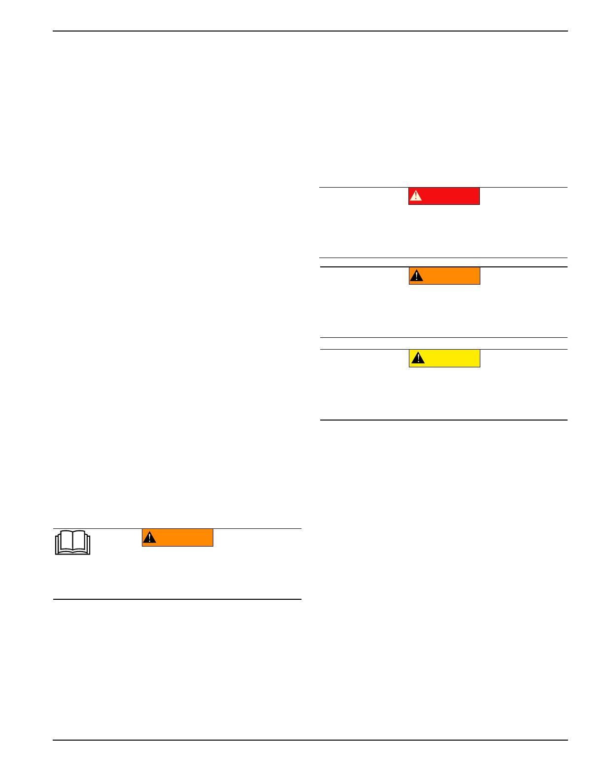
(000001)
DANGER
Indicates a hazardous situation which, if not avoided,
will result in death or serious injury.
(000002)
WARNING
Indicates a hazardous situation which, if not avoided,
could result in death or serious injury.
(000003)
CAUTION
Indicates a hazardous situation which, if not avoided,
could result in minor or moderate injury.


