HAGER COMP
ANIES
• 139 Victor Street, St. Louis, MO 63104 • 800-325-9995 • Fax (800) 782-0149 • www
.hager
co.com
6
Interior Door Width
24"
(610mm)
30"
(762mm)
34"
(865mm)
38"
(965mm)
48"
(1219mm)
54"
(1372mm)
Size 2
(5ccw)
Size 3
(0)
Size 4
(5cw)
Size 5
(10cw)
Size 1
(5ccw)
Size 1
(10ccw)
Size 2
(0)
Size 3
(5cw)
Size 4
(10cw)
Exterior (and Vestibule) Door Width
24"
(610mm)
30"
(762mm)
36"
(914mm)
42"
(1067mm)
Size 3
(0)
Size 4
(5cw)
Size 5
(10cw)
Size 3
(5cw)
Size 4
(10cw)
Regular Arm &
Top Jamb
Parallel Arm
Regular Arm &
Top Jamb
Parallel Arm
Minimum Door Width (24")
Minimum Door Width (24")
L
S
L
S
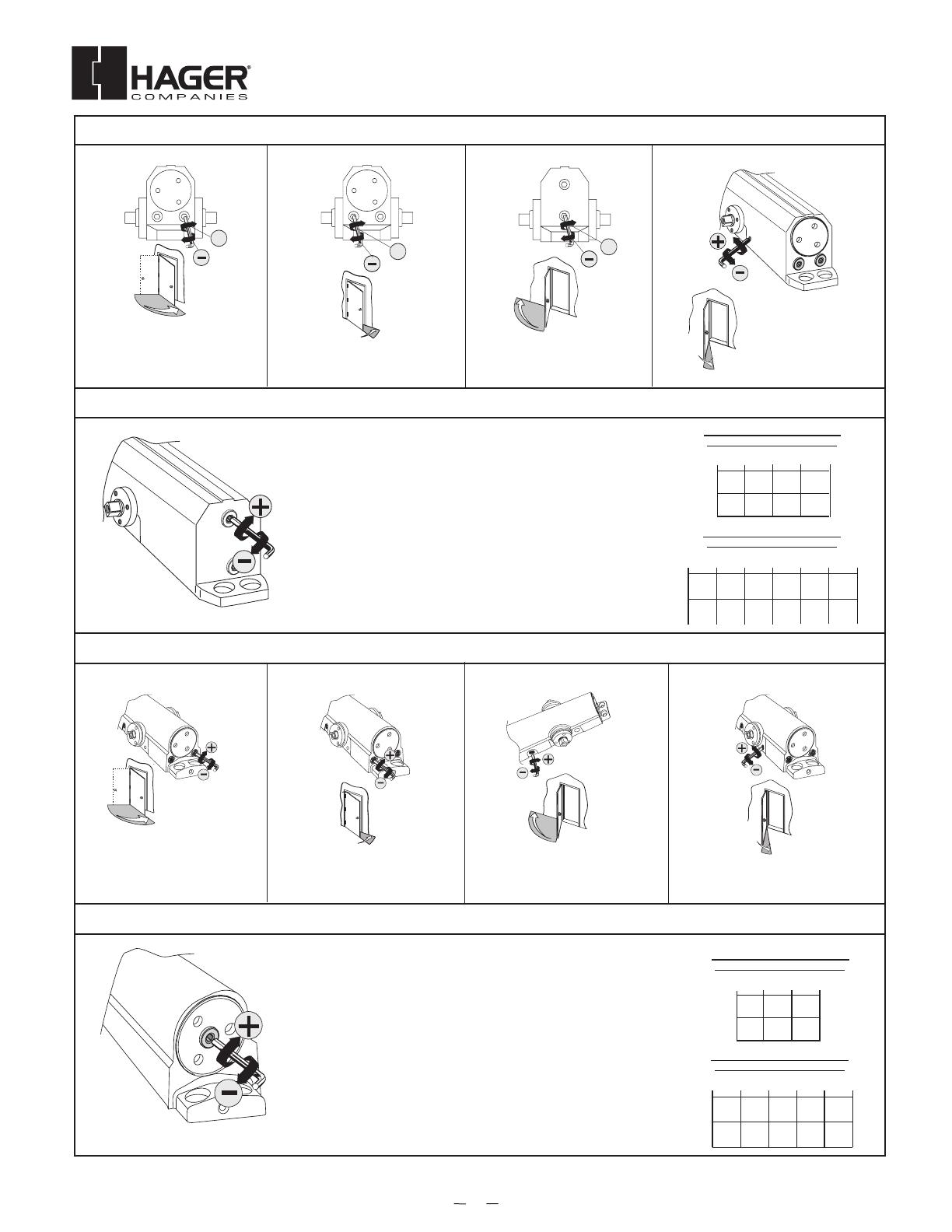
ADJUSTMENTS (USE 5/32" HEX WRENCH FOR THESE ADJUSTMENTS)
SPRING POWER ADJUST (Sizing in accordance to BHMA/ANSI 156.4)
SWEEP SPEED LATCH SPEED BACKCHECK
(Use 5/32" Hex Wrench
for this adjustment)
Adjust latch speed so door
completely closes and latches.
Adjust backcheck accordingly
to prevent excessive opening
speed.
Note: Adjust closing time speed
to between 3 and 7 seconds
from 90˚ to 0˚. Greater closing
times may be required for
elderly or handicapped.
TABLE OF SIZES
Closer is shipped set to size
3. To change the closer size,
use a hex wrench to rotate
the spring power adjust.
Follow the chart to make the
correct numbers of 360°
turns to set the closer size
appropriately for the door
application.
The number of turns is an
approximation and does not
account for environmental or
door hardware affects.
Approx. 5 turns to
increase / decrease one size.
cw = clockwise
ccw = counterclockwise
---
-----
OPTIONAL DELAY ACTION
Adjust delay action accordingly to
obtain desired delay time.
L
S
Interior Door Width
24"
(610mm)
30"
(762mm)
34"
(865mm)
38"
(965mm)
48"
(1219mm)
54"
(1372mm)
Size 2
(5ccw)
Size 3
(0)
Size 4
(5cw)
Size 5
(10cw)
Size 1
(5ccw)
Size 1
(10ccw)
Size 2
(0)
Size 3
(5cw)
Size 4
(10cw)
Exterior (and Vestibule) Door Width
24"
(610mm)
30"
(762mm)
36"
(914mm)
42"
(1067mm)
Size 3
(0)
Size 4
(5cw)
Size 5
(10cw)
Size 3
(5cw)
Size 4
(10cw)
Regular Arm &
Top Jamb
Parallel Arm
Regular Arm &
Top Jamb
Parallel Arm
Minimum Door Width (24")
Minimum Door Width (24")
L
S
L
S
ADJUSTMENTS (USE 5/32" HEX WRENCH FOR THESE ADJUSTMENTS)
SPRING POWER ADJUST (Sizing in accordance to BHMA/ANSI 156.4)
SWEEP SPEED LATCH SPEED BACKCHECK
(Use 5/32" Hex Wrench
for this adjustment)
Adjust latch speed so door
completely closes and latches.
Adjust backcheck accordingly
to prevent excessive opening
speed.
Note: Adjust closing time speed
to between 3 and 7 seconds
from 90˚ to 0˚. Greater closing
times may be required for
elderly or handicapped.
TABLE OF SIZES
Closer is shipped set to size
3. To change the closer size,
use a hex wrench to rotate
the spring power adjust.
Follow the chart to make the
correct numbers of 360°
turns to set the closer size
appropriately for the door
application.
The number of turns is an
approximation and does not
account for environmental or
door hardware affects.
Approx. 5 turns to
increase / decrease one size.
cw = clockwise
ccw = counterclockwise
---
-----
OPTIONAL DELAY ACTION
Adjust delay action accordingly to
obtain desired delay time.
L
S
5300 CLOSER ADJUSTMENTS (USE 5/32" HEX WRENCH FOR THESE ADJUSTMENTS)
SPRING POWER ADJUST (SIZING IN ACCORDANCE TO BHMA/ANSI 156.4)
L
S
L
S
+
+
B
C
+
SPRING POWER ADJUST (Sizing in accordance to BHMA/ANSI 156.4)
SWEEP SPEED LATCH SPEED BACKCHECK OPTIONAL DELAY ACTION
Adjust latch speed so door
c
ompletely closes and latches.
A
djust backcheck accordingly
t
o prevent excessive opening
speed.
Note: Adjust closing time speed
t
o between 3 and 7 seconds
from 90˚ to 0˚. Greater closing
t
imes may be required for
e
lderly or handicapped.
Interior Door Width
24"
(610mm)
30"
(762mm)
34"
(865mm)
38"
(965mm)
48"
(1219mm)
54"
(1372mm)
Size 2
(5ccw)
Size 3
(0)
Size 4
(5cw)
Size 5
(10cw)
Size 6
(15cw)
Size 1
(5ccw)
Size 1
(
10ccw)
Size 2
(0)
Size 3
(5cw)
Size 4
(10cw)
Size 5
(15cw)
Exterior (and Vestibule) Door Width
24"
(
610mm)
30"
(
762mm)
36"
(
914mm)
42"
(
1067mm)
48"
(
1219mm)
S
ize 3
(
0)
S
ize 4
(
5cw)
S
ize 4
(10cw)
S
ize 5
(15cw)
S
ize 5
(
10cw)
S
ize 6
(
15cw)
Size 3
(5cw)
Regular Arm &
Top Jamb
Parallel Arm
Regular Arm &
Top Jamb
Parallel Arm
Minimum Door Width (24")
Minimum Door Width (24")
(Use 5/32" Hex Wrench
for this adjustment)
TABLE OF SIZES
Closer is shipped set to size
3. To change the closer size,
u
se a hex wrench to rotate
t
he spring power adjust.
Follow the chart to make the
correct numbers of 360°
turns to set the closer size
a
ppropriately for the door
application.
The number of turns is an
approximation and does not
account for environmental or
door hardware affects.
Approx. 5 turns to
increase / decrease one size.
cw = clockwise
ccw = counterclockwise
-
---
-
----
60"
(1524mm)
-
L
S
A
djust delay action accordingly to
o
btain desired delay time.
BC
L
S
L
S
+
+
BC
+
SPRING POWER ADJUST (Sizing in accordance to BHMA/ANSI 156.4)
SWEEP SPEED LATCH SPEED BACKCHECK OPTIONAL DELAY ACTION
Adjust latch speed so door
completely closes and latches.
Adjust backcheck accordingly
to prevent excessive opening
speed.
Note: Adjust closing time speed
t
o between 3 and 7 seconds
from 90˚ to 0˚. Greater closing
times may be required for
elderly or handicapped.
I
nterior Door Width
24"
(
610mm)
30"
(
762mm)
34"
(
865mm)
38"
(
965mm)
48"
(
1219mm)
54"
(
1372mm)
Size 2
(
5ccw)
Size 3
(
0)
Size 4
(
5cw)
Size 5
(
10cw)
Size 6
(
15cw)
Size 1
(
5ccw)
Size 1
(10ccw)
Size 2
(
0)
Size 3
(
5cw)
Size 4
(
10cw)
Size 5
(
15cw)
Exterior (and Vestibule) Door Width
24"
(610mm)
30"
(762mm)
36"
(914mm)
42"
(1067mm)
48"
(1219mm)
S
ize 3
(0)
S
ize 4
(5cw)
S
ize 4
(
10cw)
S
ize 5
(
15cw)
S
ize 5
(10cw)
S
ize 6
(15cw)
Size 3
(
5cw)
Regular Arm &
T
op Jamb
Parallel Arm
R
egular Arm &
T
op Jamb
P
arallel Arm
Minimum Door Width (24")
Minimum Door Width (24")
(Use 5/32" Hex Wrench
for this adjustment)
TABLE OF SIZES
Closer is shipped set to size
3
. To change the closer size,
use a hex wrench to rotate
the spring power adjust.
Follow the chart to make the
correct numbers of 360°
t
urns to set the closer size
a
ppropriately for the door
a
pplication.
T
he number of turns is an
approximation and does not
account for environmental or
d
oor hardware affects.
Approx. 5 turns to
i
ncrease / decrease one size.
cw = clockwise
ccw = counterclockwise
-
---
-----
60"
(
1524mm)
-
L
S
Adjust delay action accordingly to
obtain desired delay time.
BC
L
S
L
S
+
+
BC
+
SPRING POWER ADJUST (Sizing in accordance to BHMA/ANSI 156.4)
SWEEP SPEED LATCH SPEED BACKCHECK OPTIONAL DELAY ACTION
A
djust latch speed so door
completely closes and latches.
Adjust backcheck accordingly
to prevent excessive opening
s
peed.
Note: Adjust closing time speed
to between 3 and 7 seconds
from 90˚ to 0˚. Greater closing
times may be required for
elderly or handicapped.
Interior Door Width
24"
(
610mm)
30"
(
762mm)
34"
(
865mm)
38"
(
965mm)
48"
(
1219mm)
54"
(
1372mm)
Size 2
(5ccw)
Size 3
(0)
Size 4
(5cw)
Size 5
(10cw)
Size 6
(15cw)
Size 1
(5ccw)
Size 1
(10ccw)
Size 2
(0)
Size 3
(5cw)
Size 4
(10cw)
Size 5
(15cw)
Exterior (and Vestibule) Door Width
24"
(610mm)
30"
(762mm)
36"
(914mm)
42"
(1067mm)
48"
(1219mm)
Size 3
(0)
Size 4
(5cw)
Size 4
(10cw)
Size 5
(15cw)
Size 5
(10cw)
Size 6
(15cw)
S
ize 3
(
5cw)
Regular Arm &
T
op Jamb
Parallel Arm
Regular Arm &
Top Jamb
Parallel Arm
Minimum Door Width (24")
Minimum Door Width (24")
(Use 5/32" Hex Wrench
f
or this adjustment)
TABLE OF SIZES
Closer is shipped set to size
3. To change the closer size,
use a hex wrench to rotate
the spring power adjust.
Follow the chart to make the
c
orrect numbers of 360°
turns to set the closer size
appropriately for the door
application.
T
he number of turns is an
approximation and does not
a
ccount for environmental or
door hardware affects.
Approx. 5 turns to
increase / decrease one size.
cw = clockwise
ccw = counterclockwise
----
-----
60"
(
1524mm)
-
L
S
Adjust delay action accordingly to
obtain desired delay time.
BC
L
S
L
S
+
+
B
C
+
SPRING POWER ADJUST (Sizing in accordance to BHMA/ANSI 156.4)
SWEEP SPEED LATCH SPEED BACKCHECK OPTIONAL DELAY ACTION
Adjust latch speed so door
completely closes and latches.
Adjust backcheck accordingly
to prevent excessive opening
speed.
Note: Adjust closing time speed
to between 3 and 7 seconds
from 90˚ to 0˚. Greater closing
times may be required for
elderly or handicapped.
I
nterior Door Width
24"
(
610mm)
30"
(
762mm)
34"
(
865mm)
38"
(
965mm)
48"
(
1219mm)
54"
(
1372mm)
Size 2
(5ccw)
Size 3
(0)
Size 4
(5cw)
Size 5
(10cw)
Size 6
(15cw)
Size 1
(5ccw)
S
ize 1
(10ccw)
Size 2
(0)
Size 3
(5cw)
Size 4
(10cw)
Size 5
(15cw)
E
xterior (and Vestibule) Door Width
24"
(610mm)
30"
(762mm)
36"
(914mm)
42"
(1067mm)
48"
(1219mm)
Size 3
(0)
Size 4
(5cw)
Size 4
(
10cw)
Size 5
(
15cw)
Size 5
(10cw)
Size 6
(15cw)
Size 3
(5cw)
Regular Arm &
Top Jamb
Parallel Arm
R
egular Arm &
Top Jamb
P
arallel Arm
Minimum Door Width (24")
Minimum Door Width (24")
(
Use 5/32" Hex Wrench
for this adjustment)
TABLE OF SIZES
C
loser is shipped set to size
3
. To change the closer size,
use a hex wrench to rotate
the spring power adjust.
F
ollow the chart to make the
correct numbers of 360°
turns to set the closer size
appropriately for the door
a
pplication.
The number of turns is an
approximation and does not
account for environmental or
d
oor hardware affects.
Approx. 5 turns to
increase / decrease one size.
cw = clockwise
ccw = counterclockwise
----
-----
60"
(
1524mm)
-
L
S
Adjust delay action accordingly to
obtain desired delay time.
BC
L
S
L
S
+
+
B
C
+
SPRING POWER ADJUST (Sizing in accordance to BHMA/ANSI 156.4)
SWEEP SPEED LATCH SPEED BACKCHECK OPTIONAL DELAY ACTION
Adjust latch speed so door
c
ompletely closes and latches.
Adjust backcheck accordingly
to prevent excessive opening
speed.
Note: Adjust closing time speed
t
o between 3 and 7 seconds
from 90˚ to 0˚. Greater closing
times may be required for
e
lderly or handicapped.
Interior Door Width
24"
(610mm)
30"
(762mm)
34"
(865mm)
38"
(965mm)
48"
(1219mm)
54"
(1372mm)
Size 2
(5ccw)
Size 3
(0)
Size 4
(5cw)
Size 5
(10cw)
Size 6
(15cw)
Size 1
(5ccw)
Size 1
(10ccw)
Size 2
(0)
Size 3
(5cw)
Size 4
(10cw)
Size 5
(15cw)
E
xterior (and Vestibule) Door Width
2
4"
(610mm)
3
0"
(762mm)
3
6"
(914mm)
4
2"
(1067mm)
4
8"
(1219mm)
S
ize 3
(0)
S
ize 4
(5cw)
Size 4
(
10cw)
Size 5
(
15cw)
S
ize 5
(10cw)
S
ize 6
(15cw)
S
ize 3
(5cw)
R
egular Arm &
Top Jamb
Parallel Arm
Regular Arm &
Top Jamb
Parallel Arm
Minimum Door Width (24")
Minimum Door Width (24")
(Use 5/32" Hex Wrench
for this adjustment)
T
ABLE OF SIZES
Closer is shipped set to size
3. To change the closer size,
u
se a hex wrench to rotate
the spring power adjust.
Follow the chart to make the
correct numbers of 360°
turns to set the closer size
a
ppropriately for the door
application.
T
he number of turns is an
approximation and does not
account for environmental or
door hardware affects.
Approx. 5 turns to
increase / decrease one size.
cw = clockwise
ccw = counterclockwise
----
-----
60"
(1524mm)
-
L
S
A
djust delay action accordingly to
obtain desired delay time.
BC
SPRING POWER ADJUST (SIZING IN ACCORDANCE TO BHMA/ANSI 156.4)
Interior Door Width
24"
(610mm)
30"
(762mm)
34"
(865mm)
38"
(965mm)
48"
(1219mm)
54"
(1372mm)
Size 2
(5ccw)
Size 3
(0)
Size 4
(5cw)
Size 5
(10cw)
Size 1
(5ccw)
Size 1
(10ccw)
Size 2
(0)
Size 3
(5cw)
Size 4
(10cw)
Exterior (and Vestibule) Door Width
24"
(610mm)
30"
(762mm)
36"
(914mm)
42"
(1067mm)
Size 3
(0)
Size 4
(5cw)
Size 5
(10cw)
Size 3
(5cw)
Size 4
(10cw)
Regular Arm &
Top Jamb
Parallel Arm
Regular Arm &
Top Jamb
Parallel Arm
Minimum Door Width (24")
Minimum Door Width (24")
L
S
L
S
ADJUSTMENTS (USE 5/32" HEX WRENCH FOR THESE ADJUSTMENTS)
SPRING POWER ADJUST (Sizing in accordance to BHMA/ANSI 156.4)
SWEEP SPEED LATCH SPEED BACKCHECK
(Use 5/32" Hex Wrench
for this adjustment)
Adjust latch speed so door
completely closes and latches.
Adjust backcheck accordingly
to prevent excessive opening
speed.
Note: Adjust closing time speed
to between 3 and 7 seconds
from 90˚ to 0˚. Greater closing
times may be required for
elderly or handicapped.
TABLE OF SIZES
Closer is shipped set to size
3. To change the closer size,
use a hex wrench to rotate
the spring power adjust.
Follow the chart to make the
correct numbers of 360°
turns to set the closer size
appropriately for the door
application.
The number of turns is an
approximation and does not
account for environmental or
door hardware affects.
Approx. 5 turns to
increase / decrease one size.
cw = clockwise
ccw = counterclockwise
---
-----
OPTIONAL DELAY ACTION
Adjust delay action accordingly to
obtain desired delay time.
L
S
5200 CLOSER ADJUSTMENTS (USE 5/32" HEX WRENCH FOR THESE ADJUSTMENTS)
Interior Door Width
24"
(610mm)
30"
(762mm)
34"
(865mm)
38"
(965mm)
48"
(1219mm)
54"
(1372mm)
Size 2
(5ccw)
Size 3
(0)
Size 4
(5cw)
Size 5
(10cw)
Size 1
(5ccw)
Size 1
(10ccw)
Size 2
(0)
Size 3
(5cw)
Size 4
(10cw)
Exterior (and Vestibule) Door Width
24"
(610mm)
30"
(762mm)
36"
(914mm)
42"
(1067mm)
Size 3
(0)
Size 4
(5cw)
Size 5
(10cw)
Size 3
(5cw)
Size 4
(10cw)
Regular Arm &
Top Jamb
Parallel Arm
Regular Arm &
Top Jamb
Parallel Arm
Minimum Door Width (24")
Minimum Door Width (24")
L
S
L
S
ADJUSTMENTS (USE 5/32" HEX WRENCH FOR THESE ADJUSTMENTS)
SPRING POWER ADJUST (Sizing in accordance to BHMA/ANSI 156.4)
SWEEP SPEED LATCH SPEED BACKCHECK
(Use 5/32" Hex Wrench
for this adjustment)
Adjust latch speed so door
completely closes and latches.
Adjust backcheck accordingly
to prevent excessive opening
speed.
Note: Adjust closing time speed
to between 3 and 7 seconds
from 90˚ to 0˚. Greater closing
times may be required for
elderly or handicapped.
TABLE OF SIZES
Closer is shipped set to size
3. To change the closer size,
use a hex wrench to rotate
the spring power adjust.
Follow the chart to make the
correct numbers of 360°
turns to set the closer size
appropriately for the door
application.
The number of turns is an
approximation and does not
account for environmental or
door hardware affects.
Approx. 5 turns to
increase / decrease one size.
cw = clockwise
ccw = counterclockwise
---
-----
OPTIONAL DELAY ACTION
Adjust delay action accordingly to
obtain desired delay time.
L
S
L
S
L
S
+
+
B
C
+
SPRING POWER ADJUST (Sizing in accordance to BHMA/ANSI 156.4)
SWEEP SPEED LATCH SPEED BACKCHECK OPTIONAL DELAY ACTION
Adjust latch speed so door
c
ompletely closes and latches.
A
djust backcheck accordingly
t
o prevent excessive opening
speed.
Note: Adjust closing time speed
t
o between 3 and 7 seconds
from 90˚ to 0˚. Greater closing
t
imes may be required for
e
lderly or handicapped.
Interior Door Width
24"
(610mm)
30"
(762mm)
34"
(865mm)
38"
(965mm)
48"
(1219mm)
54"
(1372mm)
Size 2
(5ccw)
Size 3
(0)
Size 4
(5cw)
Size 5
(10cw)
Size 6
(15cw)
Size 1
(5ccw)
Size 1
(
10ccw)
Size 2
(0)
Size 3
(5cw)
Size 4
(10cw)
Size 5
(15cw)
Exterior (and Vestibule) Door Width
24"
(
610mm)
30"
(
762mm)
36"
(
914mm)
42"
(
1067mm)
48"
(
1219mm)
S
ize 3
(
0)
S
ize 4
(
5cw)
S
ize 4
(10cw)
S
ize 5
(15cw)
S
ize 5
(
10cw)
S
ize 6
(
15cw)
Size 3
(5cw)
Regular Arm &
Top Jamb
Parallel Arm
Regular Arm &
Top Jamb
Parallel Arm
Minimum Door Width (24")
Minimum Door Width (24")
(Use 5/32" Hex Wrench
for this adjustment)
TABLE OF SIZES
Closer is shipped set to size
3. To change the closer size,
u
se a hex wrench to rotate
t
he spring power adjust.
Follow the chart to make the
correct numbers of 360°
turns to set the closer size
a
ppropriately for the door
application.
The number of turns is an
approximation and does not
account for environmental or
door hardware affects.
Approx. 5 turns to
increase / decrease one size.
cw = clockwise
ccw = counterclockwise
-
---
-
----
60"
(1524mm)
-
L
S
A
djust delay action accordingly to
o
btain desired delay time.
BC
L
S
L
S
+
+
B
C
+
S
PRING POWER ADJUST (Sizing in accordance to BHMA/ANSI 156.4)
SWEEP SPEED LATCH SPEED BACKCHECK OPTIONAL DELAY ACTION
Adjust latch speed so door
completely closes and latches.
Adjust backcheck accordingly
to prevent excessive opening
s
peed.
N
ote: Adjust closing time speed
to between 3 and 7 seconds
from 90˚ to 0˚. Greater closing
times may be required for
elderly or handicapped.
I
nterior Door Width
24"
(610mm)
30"
(762mm)
34"
(865mm)
38"
(965mm)
48"
(1219mm)
54"
(1372mm)
Size 2
(
5ccw)
Size 3
(
0)
Size 4
(
5cw)
Size 5
(
10cw)
Size 6
(
15cw)
Size 1
(5ccw)
Size 1
(10ccw)
Size 2
(0)
Size 3
(5cw)
Size 4
(10cw)
Size 5
(15cw)
E
xterior (and Vestibule) Door Width
24"
(610mm)
30"
(762mm)
36"
(914mm)
42"
(1067mm)
48"
(1219mm)
Size 3
(0)
Size 4
(5cw)
Size 4
(10cw)
Size 5
(15cw)
Size 5
(10cw)
Size 6
(15cw)
Size 3
(5cw)
R
egular Arm &
T
op Jamb
Parallel Arm
Regular Arm &
Top Jamb
Parallel Arm
M
inimum Door Width (24")
Minimum Door Width (24")
(
Use 5/32" Hex Wrench
f
or this adjustment)
T
ABLE OF SIZES
Closer is shipped set to size
3
. To change the closer size,
use a hex wrench to rotate
the spring power adjust.
Follow the chart to make the
correct numbers of 360°
turns to set the closer size
appropriately for the door
application.
The number of turns is an
approximation and does not
a
ccount for environmental or
door hardware affects.
Approx. 5 turns to
increase / decrease one size.
cw = clockwise
ccw = counterclockwise
----
-----
60"
(1524mm)
-
L
S
Adjust delay action accordingly to
obtain desired delay time.
BC
Note: Adjust closing time speed between
3
and 7 seconds from 90° to 0°. Greater
c
losing times may be required for elderly
or handicapped.
Note: Adjust closing time speed between
3 and 7 seconds from 90
°
to 0°. Greater
closing times may be required for elderly
or handicapped.
Adjust latch speed so door completely
closes and latches.
Adjust backcheck accordingly to prevent
excessive opening speed.
Adjust delay action accordingly to obtain
desired delay time.
A
djust latch speed so door completely
closes and latches.
A
djust backcheck accordingly to
prevent excessive opening speed.
A
djust delay action accordingly
to obtain desired delay time.
TABLE OF SIZES
Closer is shipped set to size 3. To change the closer size, use a
hex wrench to rotate the spring power adjust. Follow the chart
to make the correct number of 360° turns to set the closer size
appropriately for the door application.
The number of turns is an approximation and does not account
for environmental or door hardware affects.
Interior Door Width
24"
(610mm)
30"
(762mm)
34"
(865mm)
38"
(965mm)
48"
(1219mm)
54"
(1372mm)
Size 2
(5ccw)
Size 3
(0)
Size 4
(5cw)
Size 5
(10cw)
Size 1
(5ccw)
Size 1
(10ccw)
Size 2
(0)
Size 3
(5cw)
Size 4
(10cw)
Exterior (and Vestibule) Door Width
24"
(610mm)
30"
(762mm)
36"
(914mm)
42"
(1067mm)
Size 3
(0)
Size 4
(5cw)
Size 5
(10cw)
Size 3
(5cw)
Size 4
(10cw)
Regular Arm &
Top Jamb
Parallel Arm
Regular Arm &
Top Jamb
Parallel Arm
Minimum Door Width (24")
Minimum Door Width (24")
L
S
L
S
ADJUSTMENTS (USE 5/32" HEX WRENCH FOR THESE ADJUSTMENTS)
SPRING POWER ADJUST (Sizing in accordance to BHMA/ANSI 156.4)
SWEEP SPEED LATCH SPEED BACKCHECK
(Use 5/32" Hex Wrench
for this adjustment)
Adjust latch speed so door
completely closes and latches.
Adjust backcheck accordingly
to prevent excessive opening
speed.
Note: Adjust closing time speed
to between 3 and 7 seconds
from 90˚ to 0˚. Greater closing
times may be required for
elderly or handicapped.
TABLE OF SIZES
Closer is shipped set to size
3. To change the closer size,
use a hex wrench to rotate
the spring power adjust.
Follow the chart to make the
correct numbers of 360°
turns to set the closer size
appropriately for the door
application.
The number of turns is an
approximation and does not
account for environmental or
door hardware affects.
Approx. 5 turns to
increase / decrease one size.
cw = clockwise
ccw = counterclockwise
---
-----
OPTIONAL DELAY ACTION
Adjust delay action accordingly to
obtain desired delay time.
L
S
T
ABLE OF SIZES
Closer is shipped set to size 3. To change the closer size, use a hex
wrench to rotate the spring power adjust. Follow the chart to make the
correct number of 360° turns to set the closer size appropriately for the
door application.
The number of turns is an approximation and does not account for envi-
ronmental or door hardware affects.
Interior Door Width
24"
(610mm)
30"
(762mm)
34"
(865mm)
38"
(965mm)
48"
(1219mm)
54"
(1372mm)
Size 2
(5ccw)
Size 3
(0)
Size 4
(5cw)
Size 5
(10cw)
Size 1
(5ccw)
Size 1
(10ccw)
Size 2
(0)
Size 3
(5cw)
Size 4
(10cw)
Exterior (and Vestibule) Door Width
24"
(610mm)
30"
(762mm)
36"
(914mm)
42"
(1067mm)
Size 3
(0)
Size 4
(5cw)
Size 5
(10cw)
Size 3
(5cw)
Size 4
(10cw)
Regular Arm &
Top Jamb
Parallel Arm
Regular Arm &
Top Jamb
Parallel Arm
Minimum Door Width (24")
Minimum Door Width (24")
L
S
L
S
ADJUSTMENTS (USE 5/32" HEX WRENCH FOR THESE ADJUSTMENTS)
SPRING POWER ADJUST (Sizing in accordance to BHMA/ANSI 156.4)
SWEEP SPEED LATCH SPEED BACKCHECK
(Use 5/32" Hex Wrench
for this adjustment)
Adjust latch speed so door
completely closes and latches.
Adjust backcheck accordingly
to prevent excessive opening
speed.
Note: Adjust closing time speed
to between 3 and 7 seconds
from 90˚ to 0˚. Greater closing
times may be required for
elderly or handicapped.
TABLE OF SIZES
Closer is shipped set to size
3. To change the closer size,
use a hex wrench to rotate
the spring power adjust.
Follow the chart to make the
correct numbers of 360°
turns to set the closer size
appropriately for the door
application.
The number of turns is an
approximation and does not
account for environmental or
door hardware affects.
Approx. 5 turns to
increase / decrease one size.
cw = clockwise
ccw = counterclockwise
---
-----
OPTIONAL DELAY ACTION
Adjust delay action accordingly to
obtain desired delay time.
L
S
S
WEEP SPEED
L
ATCH SPEED
B
ACKCHECK
O
PTIONAL DELAY ACTION
SWEEP SPEED LATCH SPEED BACKCHECK OPTIONAL DELAY ACTION
5906, 5907, 5911, 5912 Heavy Duty Parallel Arm
Installation Instructions
Meets ANSI A156.4


