Duke Manufacturing FWM3-13 (Renau) Operating instructions

Type
Operating instructions
Installation and
Operation Manual
PRODUCT HOLDING
CABINET
Please read this manual completely before attempting
to install, operate or service this equipment
This manual is Copyright © 2008 Duke Manufacturing Co. All rights reserved.
Reproduction without written permission is prohibited. Duke is a registered
trademark of the Duke Manufacturing Co.
Duke Manufacturing Co.
2305 N. Broadway
St. Louis, MO 63102
Phone: 314-231-1130
Toll Free: 1-800-735-3853
Fax: 314-231-5074
www.dukemfg.com
P/N 156237C
MODELS
FWM3-13
FWM3-14
FWM3-22
FWM3-23
FWM3-24
FWM3-42
Installation and Operation of Product Holding Cabinets
2
TABLE OF CONTENTS
ELECTRICAL WARNINGS ................................................................................................3
MANUFACTURER’S INTRODUCTION .............................................................................5
SPECIFICATIONS .............................................................................................................6
Model FWM3-13 .........................................................................................................6
Model FWM3-14 .........................................................................................................7
Model FWM3-22 .........................................................................................................8
Model FWM3-23 .........................................................................................................9
Model FWM3-24 .......................................................................................................10
Model FWM3-42 ....................................................................................................... 11
INSTALLATION INSTRUCTIONS ...................................................................................12
Stacking Units ..........................................................................................................12
OPERATION ....................................................................................................................13
OPENING CHECKLIST ............................................................................................13
OPERATION INSTRUCTIONS AND ADJUSTMENTS .............................................13
CLOSING CHECKLIST ............................................................................................13
CLEANING INSTRUCTIONS ...................................................................................13
STAINLESS STEEL CARE .......................................................................................13
Cleaning ............................................................................................................13
Preserving & Restoring .....................................................................................14
Heat Tint ............................................................................................................14
KEYPAD PROGRAMMING .............................................................................................14
Power Up ..................................................................................................................14
Timer Operation ........................................................................................................15
Time Decrement .......................................................................................................15
Menu Mode ..............................................................................................................16
Enter Menu Mode ..............................................................................................16
Change Meal Set ...............................................................................................16
Display Link, Hold Time & Temperature ............................................................16
Exit Menu Mode ................................................................................................16
TROUBLESHOOTING ....................................................................................................17
Electronic Control Fault Indications ..........................................................................17
Temperature Check Procedure ................................................................................17
Service Hot-Line .......................................................................................................17
PARTS LISTS AND ILLUSTRATIONS.............................................................................18
WIRING SCHEMATICS ...................................................................................................21
3
Installation and Operation of Product Holding Cabinets
ELECTRICAL WARNINGS
THIS MANUAL HAS BEEN PREPARED FOR PERSONNEL QUALIFIED TO INSTALL
ELECTRICAL EQUIPMENT, WHO SHOULD PERFORM THE INITIAL FIELD STARTUP
AND ADJUSTMENTS OF THE EQUIPMENT COVERED BY THIS MANUAL.
READ THIS MANUAL THOROUGHLY BEFORE OPERATING, INSTALLING OR PERFORMING
MAINTENANCE ON THE EQUIPMENT.
: Failure to follow all the instructions in this manual can cause
property damage, injury or death.
: Improper installation, adjustment, alteration, service or maintenance
can cause property damage, injury or death.
: Electrical connections should be performed only by a certied
professional.
: Electrical and grounding connections must comply with the applicable
portions of the National Electric Code and/or all local electric codes. Failure to
comply with this procedure can cause property damage, injury or death.
: Before connecting the unit to the electrical supply, verify that the
electrical and grounding connections comply with the applicable portions of the
National Electric Code and/or other local electrical codes. Failure to comply with
this procedure can cause property damage, injury or death.
: Before connecting the unit to the electrical supply, verify that the
electrical connection agrees with the specications on the data plate. Failure to
comply with this procedure can cause property damage, injury or death.
: UL73 grounding instructions: This appliance must be connected to
a grounded, metal, permanent wiring system. Or an equipment-grounding conductor
must be run with the circuit conductors and connected to the equipment-grounding
terminal or lead on the appliance. Failure to comply with this procedure can cause
property damage, injury or death.
: Appliances equipped with a exible electric supply cord, are
provided with a three-prong grounding plug. It is imperative that this plug be
connected into a properly grounded three-prong receptacle. Failure to comply with
this procedure can cause property damage, injury or death.
: If the receptacle is not the proper grounding type, contact an
electrician. Do not remove the grounding prong from the plug. Failure to comply
with this procedure can cause property damage, injury or death.
Installation and Operation of Product Holding Cabinets
4
: Before performing any service that involves electrical connection
or disconnection and/or exposure to electrical components, always perform the
Electrical LOCKOUT/TAGOUT Procedure. Disconnect all circuits. Failure to comply
with this procedure can cause property damage, injury or death.
: Before removing any sheet metal panels or servicing this equipment,
always perform the Electrical LOCKOUT/TAGOUT Procedure. Be sure all circuits are
disconnected. Failure to comply with this procedure can cause property damage,
injury or death.
: Do not operate this equipment without properly placing and securing
all covers and access panels. Failure to comply with this procedure can cause
property damage, injury or death.
: Do not use or store gasoline or other ammable vapors or liquids
in the vicinity of this or any other appliance. Failure to comply can cause property
damage, injury or death.
: In the event of a power failure, do not attempt to operate this
appliance. Failure to comply can cause property damage, injury or death.
FOR YOUR SAFETY
DO NOT STORE OR USE GASOLINE OR OTHER FLAMMABLE VAPORS OR LIQUIDS
IN THE VICINITY OF THIS OR ANY OTHER APPLIANCE. FAILURE TO COMPLY CAN
CAUSE PROPERTY DAMAGE, INJURY OR DEATH.
CAUTION
Observe the following:
• Minimumclearancesmustbemaintainedfromallwallsandcombustiblematerials.
• Keeptheequipmentareafreeandclearofcombustiblematerial.
• Maintainadequateclearanceforairopenings.
• Operateequipmentonlyonthetypeofelectricityindicatedonthedatasticker.
• Retainthismanualforfuturereference.
5
Installation and Operation of Product Holding Cabinets
MANUFACTURER’S INTRODUCTION
The Duke Product Holding Unit was developed
for extended food-holding capabilities to provide
consistentlyhigh,“justcooked”foodquality.
The Duke Product Holding Unit utilizes Duke’s patented
“heat sink” holding technology that provides even heat
distribution to food pans through the bottom and sides.
This allows pre-cooked foods to be held for extended
periods without noticeable degradation of quality,
reducing food scrap/waste.
The self contained, individually formed, sealed
compartments of the Duke Product Holding Unit
eliminates food odor and taste transfer. Because the
compartments are sealed and formed to the shape of
thepan,nodisassemblyisrequiredforcleaningand
product changes.
TheuniquedesignoftheDukeProductHoldingUnit
allows single temperature operation for all existing
product groups. This 190°F approved temperature
is preset at the factory. This reduces the likelihood
of inconsistent performance between restaurant
locations.
The Duke Product Holding Cabinet was also designed
to rethermalize food product. A thermostat setting of
200°Fminimumisrequiredforre-thermalization.
Supplier Name: Duke Manufacturing Co.
Address: 2305 N. Broadway
St. Louis, MO 63102
Model #:
FWM3-13-120 FWM3-23-120
FWM3-13-208 FWM3-23-208
FWM3-13-230 FWM3-22-230
FWM3-13-240 FWM3-23-240
FWM3-14-120 FWM3-24-100
FWM3-14-208 FWM3-24-120
FWM3-14-230 FWM3-24-208
FWM3-14-240 FWM3-24-230
FWM3-24-240
FWM3-22-100 FWM3-22-100
FWM3-22-120 FWM3-22-120
FWM3-22-208 FWM3-22-208
FWM3-22-230 FWM3-22-230
FWM3-22-240 FWM3-22-240
Serial #:
Date Received:
Date Installed:
Telephone: (800) 735-DUKE (3853)
(314) 231-1130
Fax: (314) 231-5074
Service Referral #:
Local Service Name
Local Service #
Installationrequirements
PowerConnection:SeeSpecications
!CAUTION!
Risk of re or electric shock. Replace only
with Manufacturers cord set or equivalent.
Installation and Operation of Product Holding Cabinets
6
MODEL FWM3-13
MODEL NO SHIPPING WEIGHT VOLTS AC AMPS WATTS HZ
FWM3-13YM1-120 75 lbs / 34.1 Kg 120 5 600 50/60
FWM3-13YM1-208 75 lbs / 34.1 Kg 208 4.3 900 50/60
FWM3-13YM1-230CE 75 lbs / 34.1 Kg 230 3.9 900 50/60
FWM3-13YM1-240 75 lbs / 34.1 Kg 240 3.8 900 50/60
SPECIFICATIONS
7
Installation and Operation of Product Holding Cabinets
MODEL FWM3-14
MODEL NO SHIPPING WEIGHT VOLTS AC AMPS WATTS HZ
FWM3-14-120 92 lbs / 41.7 Kg 120 6.7 800 50/60
FWM3-14-208 92 lbs / 41.7 Kg 208 5.8 1200 50/60
FWM3-14-230 92 lbs / 41.7 Kg 230 5.2 1200 50/60
FWM3-14-240 92 lbs / 41.7 Kg 240 5.0 1200 50/60
Installation and Operation of Product Holding Cabinets
8
MODEL FWM3-22
MODEL NO SHIPPING WEIGHT VOLTS AC AMPS WATTS HZ
FWM3-22-100 61 lbs / 27.7 Kg 100 8.0 800 50/60
FWM3-22-120 61 lbs / 27.7 Kg 120 6.7 800 50/60
FWM3-22-208 61 lbs / 27.7 Kg 208 5.8 1200 50/60
FWM3-22-230 61 lbs / 27.7 Kg 230 5.2 1200 50/60
FWM3-22-240 61 lbs / 27.7 Kg 240 5.0 1200 50/60
9
Installation and Operation of Product Holding Cabinets
MODEL FWM3-23
MODEL NO SHIPPING WEIGHT VOLTS AC AMPS WATTS HZ
FWM3-23-120 83.5 lbs 37.9 Kg 120 10.0 1200 50/60
FWM3-23-208 83.5 lbs 37.9 Kg 208 8.7 1800 50/60
FWM3-23-230 83.5 lbs 37.9 Kg 230 7.8 1800 50/60
FWM3-23-240 83.5 lbs 37.9 Kg 240 7.5 1800 50/60
Installation and Operation of Product Holding Cabinets
10
MODEL FWM3-24
MODEL NO SHIPPING WEIGHT VOLTS AC AMPS WATTS HZ
FWM3-24-100 100 lbs / 45 Kg 100 16.0 1600 50/60
FWM3-24-120 100 lbs / 45 Kg 120 13.3 1600 50/60
FWM3-24-208 100 lbs / 45 Kg 208 11.5 2400 50/60
FWM3-24-230 100 lbs / 45 Kg 230 10.4 2400 50/60
FWM3-24-240 100 lbs / 45 Kg 240 10.0 2400 50/60
11
Installation and Operation of Product Holding Cabinets
MODEL FWM3-42
MODEL NO SHIPPING WEIGHT VOLTS AC AMPS WATTS HZ
FWM3-42-100 100 lbs / 45 Kg 100 16.0 1600 50/60
FWM3-42-120 100 lbs / 45 Kg 120 13.3 1600 50/60
FWM3-42-208 100 lbs / 45 Kg 208 11.5 2400 50/60
FWM3-42-230 100 lbs / 45 Kg 230 10.4 2400 50/60
FWM3-42-240 100 lbs / 45 Kg 240 10.0 2400 50/60
Installation and Operation of Product Holding Cabinets
12
INSTALLATION INSTRUCTIONS
1. Place the warmer onto a stable, level surface.
: Before connecting the unit to
the electrical supply, verify that the electrical
connection agrees with the specications on
the data plate. Failure to comply with this
procedure can cause property damage, injury
or death.
Screw
Figure 1: Location of Power Inlet and
Cord Clamp
2. Loosen the Cord Clamp screw.
3. Insert the Cord Set into the Power Inlet.
4. Tighten the Cord Clamp screw to prevent accidental
removal of the Cord Set.
5. Operate the unit according the Operation
Instructions provided in this manual.
Notice: Refer to the specications data plate when
ordering or replacing a cord set.
STACKING UNITS
: TIP HAZARD! Do not stack
FWM3-42 units.
: TIP HAZARD! Do not exceed
three holding cabinets per stack.
: Do not place holding cabinet
stacks on surfaces that may easily tip over.
The FWM3-24 Product Holding Cabinet is designed to
allow limited stacking capabilities. Use these procedures
to stack FWM3-24 models.
Figure 2: Removal of Base Pan
1. Remove the Base Pan from all FWM3-24s to
stacked, except the bottom unit. The pan is held in
place by two screws on the bottom of each unit.
Figure 3: Placement of Bottom Unit
2. Placebottomunitintoitsnalpositionthenstack
the next unit on top. The top of the lower holding
cabinet rests inside of the base of the upper unit.
Figure 4: FWM3-24 In Stacked Arrangement
13
Installation and Operation of Product Holding Cabinets
OPERATION
The following procedures must be performed on a
daily basis.
OPENING CHECKLIST
1. Ensure proper Pan Covers are inserted into the
correct locations for fried and broiled products.
2. Place the Power Switch, located on the front of the
Product Holding Unit, in the ON position.
3. Allow the Product Holding Cabinet to heat for at
least 20 min. or until the temperature disappears
and the menu bars display the pre-programmed
product names: “EGGS”, “FISH”, “----“ or “EMTY”
(no product).
OPERATION INSTRUCTIONS AND
ADJUSTMENTS
1. If the menu bars display temperature at any time
during operation of the Product Holding Cabinet,
discontinue use of the affected shelf until the cabinet
is serviced.
2. Refer to the Keypad Programming section of the
manual for instructions on using and programming
the keypad.
CLOSING CHECKLIST
1. Place the Power Switch in its OFF position.
2. Remove all pans and pan covers.
3. Allow the cabinet to cool for approximately
30 minutes.
4. Refer to the Cleaning Instructions section of
the manual for proper care and cleaning of the
cabinet.
: Electrical Shock Hazard, unplug
the cabinet before cleaning it.
: Do not wash with water jet
or hose.
: Bottom and sides of warmer
wells are very hot and cool slowly.
CAUTION: Do not use caustic cleaners, acids,
ammonia products or abrasive cleaners or abrasive
cloths. These can damage the stainless steel
and plastic surfaces.
CLEANING INSTRUCTIONS
1. Wipe down the interior and exterior of the Product
Holding Cabinet with warm water and mild detergent
using a soft cloth. Do not use excessive amounts
of water.
2. Clean pans and pan covers using mild detergent
and warm water.
3. Ensure all soap is rinsed from plastic pans and
pan covers.
STAINLESS STEEL CARE
Cleaning
Stainless steel contains 70-80% iron, which will rust
if not properly maintained. It also contains 12-30%
chromium, which forms an invisible passive, protective
lmthatshieldsagainstcorrosion.Ifthelmremains
intact, the stainless steel will remain intact. However,
ifthelmisdamaged,thestainlesssteelcanbreak
down and rust. To prevent stainless steel breakdown,
follow these steps:
CAUTION: Never use any metal tools. Scrapers,
les, wire brushes or scouring pads (except
for stainless steel scouring pads) will mar the
surface.
CAUTION: Never use steel wool, which will leave
behind particles that rust.
CAUTION: Never use acid-based or chloride-
containing cleaning solutions, which will break
down the protective lm.
CAUTION: Never rub in a circular motion.
Installation and Operation of Product Holding Cabinets
14
CAUTION: Never leave any food products or
salt on the surface. Many foods are acidic. Salt
contains chloride.
For routine cleaning, use warm water, mild soap or
detergent and a sponge or soft cloth.
For heavy-duty cleaning, use warm water, a degreaser
and a plastic, stainless steel or Scotch-Brite pad.
Always rinse thoroughly. Always rub gently in the
direction of the steel grain.
Preserving & Restoring
Special stainless steel polishing cleaners can preserve
andrestoretheprotectivelm.
Preserve the life of stainless steel with a regular
applicationofahighqualitystainlesssteelpolishing
cleanerasanalsteptodailycleaning.
If signs of breakdown appear, restore the stainless
steel surface. First, thoroughly clean, rinse and dry the
surface.Then,onadailybasis,applyahigh-quality
stainless steel polish according to manufacturer’s
instructions.
Heat Tint
Darkened areas, called heat tint, may appear on
stainless steel exposed to excessive heat, which causes
theprotectivelmtothicken.Itisunsightlybutisnota
sign of permanent damage.
To remove heat tint, follow the routine cleaning
procedure.Stubbornheattintwillrequireheavy-duty
cleaning.
Toreduceheattint,limittheexposureofequipment
to excessive heat.
KEYPAD PROGRAMMING
1. Status LEDs: Used for indicating status of pan.
a. Non-Illuminated
I. Timer is Inactive - no product in pan,
OR
II. Timer is Active - product in pan – use
panwithGREENSTATUSLEDrst.
b. Green = Timer is Active - product in pan
(userst)
c. Flashing Green = Cook Warning Time
reached (cook more product) or keyboard
in EDIT MODE (programming).
2. Arrow Buttons
a. Used for Starting/Stopping/Resetting
Timer.
b. Used for Programming.
c. Indicate which pan the adjacent Status
LED and Pan Display are linked to (i.e.
Status LED and Pan Display on left side
of keyboard are linked to the pan above
the keyboard and the Status LED and Pan
Display on right side of keyboard are linked
to the pan below).
3. Pan Display
a. Displays Product Name and Hold Time
Remaining (alternates between the two
when Timer is active).
4. Enter Button
a. Used for Time Decrement and Programming.
Power Up
1. Place the Power Switch in the ON position. Software
initializes at startup.
15
Installation and Operation of Product Holding Cabinets
2. Until warmer reaches preprogrammed operating
temperature, all displays will show actual
temperature.
3. When the set point is reached, Product Name
appears on all Pan Displays.
Note: For these instructions only the pertinent keypads
will be shown, for simplicity, and not the warmer or
pans. It is implied that a product pan is located above
and below each keypad.
Timer Operation
1. Press Arrow Button that corresponds to pan the
product is in. (In this example, there is product in
pan above keypad).
2. Status LED turns GREEN (unless same product
present in another pan, then Status LED will remain
non-illuminated) and Pan Display alternately shows
Time Remaining and Product Name.
3. At t=cook time (set to 4 minutes) the Status LED begins
FLASHING, alarm sounds and Display alternately
ashesTimeRemainingandProductName.
4. Push Arrow Button to silence alarm – Status LED
remainsGREENandstopsashing.
5. At t=0, alarm sounds, Status LED is FLASHING
and “00:00” is FLASHING in the Display. Discard
product in pan. Press corresponding Arrow Button
to silence alarm and reset timer.
6. Status LED becomes non-illuminated and Display
shows Product Name only. The pan is ready for
more product.
Note: To reset the time when product is depleted, press
and release the corresponding arrow key. The status
LED will become non-illuminated any status LED on
thesameproductwillturngreen,indicatinguserst.
Time Decrement
This program is used to alter Hold Time when introducing
a product from another warming unit.
Example: Transfer CORN from another warmer with
19 minutes left on Hold Time.
1. Press and hold the Arrow Button corresponding
to the pan that’s being edited for three seconds.
The display will appear as shown below with
a FLASHING Status LED and a down arrow in
the Display indicating the timer is in decrement
mode.
2. Repeatedly pressing the Arrow Button decrements
time by one minute per depression.
3. Holding down the button continuously will slow the
time down.
4. To increment time, press the Enter Button. The
arrow on display will point up to denote incrementing
time as shown below.
5. Repeatedly pressing the Arrow Button increments
time by one minute per depression.
Installation and Operation of Product Holding Cabinets
16
6. Holding down the button continuously will slew the
time up.
7. When the proper time is reached on the Display
release the Arrow Button and after 5 seconds unit will
accept new time and return to normal operation.
Menu Mode
This option is used to change Meal Set and view,
Linking, Hold Time and Hold Temp.
Enter Menu Mode
1. Press and hold the Enter Button for three seconds.
Status LED FLASHES GREEN and “MENU” is
displayed on left Display and “UP” is displayed
on right, indicating upper well information will be
displayed.
2. To view lower well information press the Down Arrow
Button – “DOWN” will appear in the right Display.
FLASHING Status LED will be present on side of
keypad corresponding to well being viewed.
3. Press the Enter Button to accept.
Change Meal Set
Note: The Meal Set can be changed globally from
any keyboard.
1. Status LED stops ashing and “MEAL” “SET1”
appears on the Display.
2. Press the Enter Button again. Status LED
FLASHES indicating edit mode.
3. Use the Arrow Buttons to scroll to desired Meal Set
and press the Enter Button to accept. Status LED
stopsashinganddesiredMealSetisdisplayed.
Display Link, Hold Time & Temperature
Press Arrow Button repeatedly to scroll through Link,
Time and Temperature settings.
Exit Menu Mode
Scroll to EXIT and press the Enter Button to exit
menu mode.
17
Installation and Operation of Product Holding Cabinets
TROUBLESHOOTING
There are no user serviceable parts on the Duke
Product Holding Cabinet. If a malfunction occurs,
ensure unit is plugged in then check all switches and
circuit breakers. If the malfunction still exists, contact
your Duke Manufacturing Company authorized service
agent or call 1-800-735-3853.
ELECTRONIC CONTROL FAULT
INDICATIONS
The keypad display provides an indication to alert the
operator to failures in the heater circuit. The possible
fault conditions are as follows:
1. Over-Temperature Fault - An over-temperature
fault occurs when the control senses that the shelf
temperature is higher than the specied factory
preset temperature for thirty minutes. This occurs
when the power is not removed from the heating
element after the shelf has achieved the preset
temperature. The auxiliary thermostat prevents the
temperature from exceeding safe levels by regulating
the temperature to a maximum of 250°F. If this
occurs, “HI” will appear on the keypad; the affected
unit should not be used until the cause of the fault
iscorrectedbyaqualiedservicetechnician.
2. Under-Temperature Fault - An under-temperature
fault occurs when the control senses that the shelf
temperature is lower than the specied factory
preset temperature for more than thirty minutes
continuously. This occurs when heating element
circuit opens or the RTD Feedback signal is faulty. If
this occurs, “LOwill appear on the keypad and the
affected unit should not be used until the cause of the
faultiscorrectedbyaqualiedservicetechnician.
3. Sensor Fault – If it any time during normal
operation “SENS” is displayed on the keypad:
discontinueoperationandcontactqualiedservice
technician.
TEMPERATURE CHECK PROCEDURE
1. A digital temperature meter that has been calibrated
must be used to get an accurate temperature
reading. Use a thermocouple surface temperature
probe to measure temperatures.
2. No pans should be in wells during the pre-heat
and temperature check. Pre-heat the warmer for
30 minutes before taking any temperature readings.
Do not take readings unless the cavity has been
empty for 30 minutes. This will allow the temperature
to stabilize and will prevent false readings.
3. The warmer cavity should be cleaned and empty
before the temperature is checked. Avoid any air
draftsthatmightowthroughthecavity.
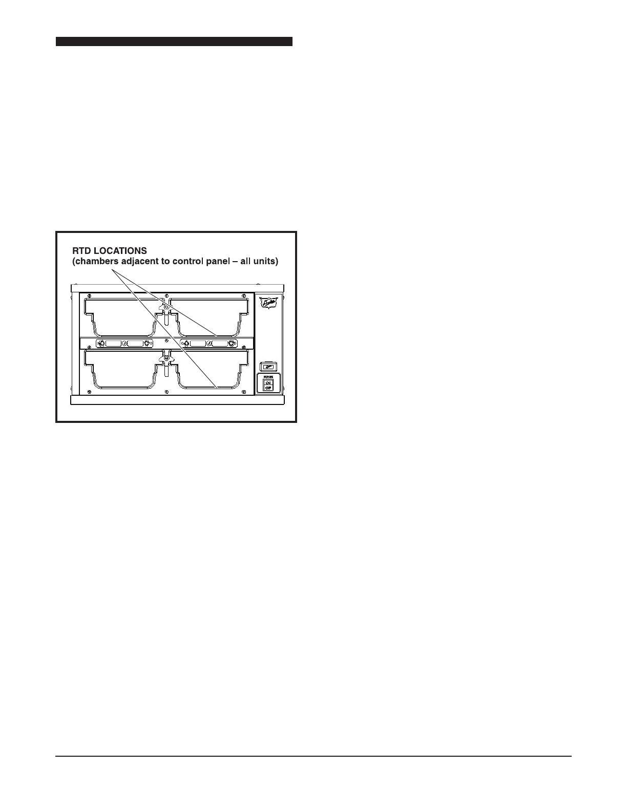
4. Locate the surface temperature probe on the bottom
oftherstcavityinthegeometriccenter.Therst
cavity is the one closest to the control panel (see
gure).Makesuretheprobeismakinggoodcontact
with the surface while taking readings.
5. All temperature controls exhibit a swing in
temperature as the control cycles on and off while
regulating to the set point. The correct calibration
temperature is the average of several readings
taken over a period of 20 minutes after the warmer
has been pre-heated. The average temperature
shouldbe±5∞Ffromthesetpoint.
SERVICE HOT-LINE
Check the display for fault messages. Perform the
Temperature Check Procedure in this manual. Make
note of thendings. Please, have this data handy
before calling the Duke troubleshooting Hot Line
listed above. For optimum support, please be near
the suspect units with a cordless phone, if available,
when calling our Technicians.
Installation and Operation of Product Holding Cabinets
18
PARTS LISTS AND ILLUSTRATIONS
8
1
10
9
11
3
4
6
7
2
5
K
Detail K
Scale 1:4
Detail L
Scale 1:3
18
19
15
17
14
16
19
Installation and Operation of Product Holding Cabinets
Quantity per Unit
Locator P/N Description FWM3-13 FWM3-14 FWM3-22 FWM3-23 FWM3-24 FWM3-42
1 157828 KEYPAD - 2 or 4 3 or 6 4 or 8 4 or 8
156292 KEYPAD – DOWN ARROWS ONLY 3 or 6 4 or 8 - - - -
2 157829 CONTROL, MAIN FWM 1 1 1 1 1 1
3 155749 TRANSFORMER, 208/240 VAC
156838 TRANSFORMER, 230 VAC 1 1 1 1 1 1
156316 TRANSFORMER, 120 VAC
4 156938 TERMINAL BLOCK 1 1 1 1 1 1
5 157830 RELAY, SMART POWER MODULE 1 1 1 1 1 2
6 155741 RECEPTACLE, ELECTRIC 1 1 1 1 1 1
7 156527 SWITCH, LIGHTED, DPST, 16A 1 1 1 1 1 1
8 157506 FACE PLATE w/GASKET, FWM3-13 2 - - - - -
156854 FACE PLATE w/GASKET, FWM3-14 - 2 - - - -
156485 FACE PLATE w/GASKET, FWM3-22 - - 2 - - -
156558 FACE PLATE w/GASKET, FWM3-23 - - - 2 - -
155849 FACE PLATE w/GASKET, FWM3-24 - - - - 2 -
156548 FACE PLATE w/GASKET, FWM3-42 - - - - - 2
9 156285 LATCH, PAN 4 4 4 8 8 8
10 156288 SCREW, SHOULDER 4 4 4 8 8 8
11 0653638 SCREW, 1/4-20 X 3/4 4 4 8 8 8 16
12 155750 RTD 1K OHM THIN 1 1 2 2 2 4
13 156994 ELEMENT FOIL HEAT 4 4 4 8
FWM3-22-100 & FWM3-42-100
156483 ELEMENT FOIL HEAT 4 4 4 8
FWM3-22-120 & FWM3-42-120
156539 ELEMENT FOIL HEAT 4 4 4 8
FWM3-22-208 & FWM3-42-208
156632 ELEMENT FOIL HEAT 4 4 4 8
FWM3-22-230CE & FWM3-42-230CE
156540 ELEMENT FOIL HEAT 4 4 4 8
FWM3-22-240 & FWM3-42-240
156564 ELEMENT FOIL HEAT 3 6
FWM3-13-120 & FWM3-23-120
156301 ELEMENT FOIL HEAT 3 6
FWM3-13-208 & FWM3-23-208
156611 ELEMENT FOIL HEAT 3 6
FWM3-13-230CE & FWM3-23-230CE
156565 ELEMENT FOIL HEAT 3 6
FWM3-13-240 & FWM3-23-240
157520 ELEMENT FOIL HEAT FWM3-24-100 8
156566 ELEMENT FOIL HEAT 4 8
FWM3-14-120 & FWM3-24-120
155752 ELEMENT FOIL HEAT 4 8
FWM3-14-208 & FWM3-24-208
156318 ELEMENT FOIL HEAT 4 8
FWM3-14-230CE & FWM3-24-230CE
Installation and Operation of Product Holding Cabinets
20
PARTS LISTS AND ILLUSTRATIONS (CONTINUED)
Quantity per Unit
Locator P/N Description FWM3-13 FWM3-14 FWM3-22 FWM3-23 FWM3-24 FWM3-42
13 155755 ELEMENT FOIL HEAT 4 8
FWM3-14-240 & FWM3-24-240
14 155753 THERMOSTAT AUXILIARY 1 1 2 2 2 4
15 155680 NUT #8-32 KEPS 2 2 4 4 4 8
16 155873 LID,FOODWARMER VENTED AR AR AR AR AR AR
(FRIED)(GRAY)
17 155876 LID,FOODWARMER SOLID AR AR AR AR AR AR
(BROILED)(BLACK)
18* 156533 CORDSET, NEMA 5-15P, 120V 1 1 1 1 1 1
(NOT SHOWN)
156811 CORDSET, NEMA 5-20P, 120V,
CANADIAN FWM3-24,-42
(NOT SHOWN)
156421 CORDSET, NEMA 6-15P, 208/240V
(NOT SHOWN)
156400 CORDSET, 230V CE (NOT SHOWN)
  • Page 1 1
  • Page 2 2
  • Page 3 3
  • Page 4 4
  • Page 5 5
  • Page 6 6
  • Page 7 7
  • Page 8 8
  • Page 9 9
  • Page 10 10
  • Page 11 11
  • Page 12 12
  • Page 13 13
  • Page 14 14
  • Page 15 15
  • Page 16 16
  • Page 17 17
  • Page 18 18
  • Page 19 19
  • Page 20 20
  • Page 21 21
  • Page 22 22
  • Page 23 23
  • Page 24 24

Duke Manufacturing FWM3-13 (Renau) Operating instructions

Type
Operating instructions

Ask a question and I''ll find the answer in the document

Finding information in a document is now easier with AI