Page is loading ...

1. Safety ........................................................................................................................................ 25
1.1 Symbols Used .................................................................................................................................................. 25
1.2 Warnings .......................................................................................................................................................... 25
1.3 Notes on CE Identification ............................................................................................................................... 26
1.4 Proper Use ....................................................................................................................................................... 27
1.5 Proper Environment ......................................................................................................................................... 27
1.6 Foreseeable Misuse ......................................................................................................................................... 27
2. Functional Principle, Technical Data ....................................................................................... 28
2.1 Functional Principle.......................................................................................................................................... 28
2.2 Structure ........................................................................................................................................................... 28
2.3 Technical Data .................................................................................................................................................. 29
3. Delivery ..................................................................................................................................... 31
3.1 Unpacking ........................................................................................................................................................ 31
3.2 Storage ............................................................................................................................................................. 31
4. Installation and Mounting ........................................................................................................ 32
4.1 Precautionary Measures .................................................................................................................................. 32
4.2 Sensor Assembly ............................................................................................................................................. 32
4.3 Wire Guide and Fastening ............................................................................................................................... 36
4.4 Connection of the Sensor ................................................................................................................................ 37
5. Operation .................................................................................................................................. 38
6. Operation and Maintenance .................................................................................................... 38
7. Warranty .................................................................................................................................... 38
8. Appendix ................................................................................................................................... 39
8.1 Accessories and Spare Parts ........................................................................................................................... 39
8.2 Drawings and References for Attachment ....................................................................................................... 39
9. Decommissioning, Disposal .................................................................................................... 42
Contents

Page 25
Safety
English
wireSENSOR, WDS MP/MPM/MPW
1. Safety
Knowledge of the instruction manual is a prerequisite for sensor operation.
1.1 Symbols Used
The following symbols are used in this instruction manual:
Indicates a hazardous situation which, if not avoided, may result in minor or moder-
ate injury.
Indicates a situation which, if not avoided, may lead to property damage.
Indicates an user action.
i
Indicates an user tip.
1.2 Warnings
The power supply may not exceed the specified limits.
> Danger of injury
> Damage to or destruction of the sensor
Do not open the sensor housing.
> Danger of injury from pre-tensioned spring motor
Do not pull or loop the measuring wire around unprotected parts of the body.
> Danger of injury
Do not let the measuring wire rewind without control (snap back).
> Danger of injury from whiplash effect of the wire with assembly bolts/clips
> Destruction of wire
> Destruction of sensor

Page 26
Safety
wireSENSOR, WDS MP/MPM/MPW
Do not pull the measuring wire over measuring range.
> Danger of injury
> Destruction of the measuring wire
> Destruction of the sensor
Avoid shock and vibration to the sensor.
> Damage to or destruction of the sensor
Power supply and the display/output device must be connected in accordance with the safety regulations for
electrical equipment.
> Damage to or destruction of the sensor
1.3 Notes on CE Identification
The following applies to series WDS draw wire sensors: Machinery Directive 2006/42/EC
The following applies to series WDS draw wire sensors with digital output:
- EU directive 2004/108/EC
- EU directive 2011/65/EC, “RoHS“ category 9
Products which carry the CE mark satisfy the requirements of the quoted EU directives and the European
standards (EN) listed therein. The EC declaration of conformity is kept available according to EU regulation,
article 10 by the authorities responsible at
MICRO-EPSILON MESSTECHNIK
GmbH & Co KG
Königbacher Straße 15
94496 Ortenburg / Germany
Draw wire sensors with potentiometer output are not automatically operable devices (components). An EC
declaration of conformity or CE identification is therefore not issued by EMC law and Machinery Directive.
Sources: EMC law, guidelines on the application of council directive 2004/108/EC, directive 2006/42/EC.

Page 27
Safety
English
wireSENSOR, WDS MP/MPM/MPW
1.4 Proper Use
Draw wire sensors are used for
- distance or displacement measuring
- position determination
of components or moving machine parts.
- The sensors may only be operated within the limits specified in the technical data (Chap. 2).
- Draw wire sensors should only be used in such a way that in case of malfunction or failure personnel or
machinery are not endangered.
- Additional precautions for safety and damage prevention must be taken for safety-related applications.
1.5 Proper Environment
- Protection class for sensor: IP 65
- Operating temperature: -20 to +80 °C (-4 to +176 °F)
- Storage temperature: -40 to +80 °C (-40 to +176 °F)
- Humidity: 5 - 95 % (non-condensing)
- Ambient pressure: Atmospheric pressure
- Vibration: According to IEC 68-2-6
- Mechanical shock: According to IEC 68-2-27
1.6 Foreseeable Misuse
Do not further extract the measuring wire but only to the specified measuring range. This may lead to dam-
age of the measuring wire and also to uncontrollable snapping of the measuring wire. Danger of injury.
Make sure the sensor is not held by another person when the measuring wire is extracted. Danger of snap-
ping and injury.

Page 28
Functional Principle, Technical Data
wireSENSOR, WDS MP/MPM/MPW
2. Functional Principle, Technical Data
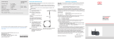
2.1 Functional Principle
With the wire principle, a linear motion is transformed into a change in resistance by a rotation.
A measuring wire made of highly flexible stainless steel wires is wound onto a drum with the aid of a long life
spring motor.
The winding drum is coupled axially with a potentiometer which converts the sensor signal into suitable
changes in resistance or voltages for consecutively interfaces.
Fig. 1 Draw-wire sensor with potentiometer
2.2 Structure
The draw-wire principle is used in several housing designs with different measuring lengths.
- Series MP, MPW - measuring ranges from 100 to 1,000 mm (3.93 to 39.37 in)
- Series MPM - measuring ranges from 50 to 250 mm (1.97 or 9.84 in)
Electrical connection:
- Potentiometer output (resistance divider)
- Encoder output (WDS-1000-MP/MPW only)Absolute encoder (with integrated electronics)

Page 29
Functional Principle, Technical Data
English
wireSENSOR, WDS MP/MPM/MPW
2.3 Technical Data
WDS-50... WDS-100... WDS-150... WDS-250... WDS-300... WDS-500... WDS-1000...
Series
MP, MPW • • • •
MPM • • •
Measuring range 50 mm 100 mm 150 mm 250 mm 300 mm 500 mm 1.000 mm
Sensor element
(potentiometer)
Conductive •
Hybrid • • • • •
Wirewound •
Encoder •
Linearity
E:<±0.05 % FSO
±0.5 mm
(0.02 inch)
±0.1 % FSO
±0.5 mm
(0.02 inch)
±1 mm
(0.04 inch)
±0.2 % FSO
±0.3 mm
(0.01 inch)
±0.5 mm
(0.02 inch)
±0.25 % FSO
±0.125 mm
(0.005 inch)
±0.75 mm
(0.03 inch)
±0.5 % FSO
±0.5 mm
(0.02 inch)
Resolution quasi infinite
Operating temperature -20 ... +80 °C (-4 to +176 °F)
Storage temperature -40 ... +80 °C (-40 to 176 °F)
Wire acceleration appr. 25 g
1)
appr. 30 g appr. 25 g
1)
appr. 25 g
1)
appr. 30 g appr. 30g appr. 30g
Wire retraction force (min) 1.5 N
2)
7 N 1.5 N
2)
1.5 N
2)
7 N 6.5 N 5 N
Wire extension force (max) 3.5 N
3)
8.5 N 3.5 N
3)
3.5 N
3)
8.5 N 8.5 N 8 N

Page 30
Functional Principle, Technical Data
wireSENSOR, WDS MP/MPM/MPW
WDS-50... WDS-100... WDS-150... WDS-250... WDS-300... WDS-500... WDS-1000...
Wire mounting thread M4
Material
Housing aluminium
Measuring wire stainless steel
Protection class
MP
IP 65 IP 65 IP 65 IP 65
MPW IP 67 IP 67 IP 67 IP 67
MPM IP 65 IP 65 IP 65
Vibration 20 g, 20 Hz - 2 kHz (IEC 68-2-6)
Mechanical shock 50 g, 10 ms (IEC 68-2-27)
Electrical connection integral cable, axial, 3-leads (0.34 mm
²)
, AWG 22), 1 m long
Weight appr. 150 g appr. 270 g appr. 150 g appr. 150 g appr. 270 g appr. 270 g appr. 270 g
Input voltage max. 32 VDC on 1 kOhm / max. 1 W
Resistance 1 kOhm ±10 % (resistance divider)
Viper current ≤3 mA; <10 µA on hybrid potentiometer
Temperature coefficient ±0.0025 % FSO/K
FSO = Fuss Scale Output
1)
Option HG: 100 g
2)
Option HG: 10 N
3)
Option HG: 17 N.

Page 31
Delivery
English
wireSENSOR, WDS MP/MPM/MPW
3. Delivery
3.1 Unpacking
Do not unpack the sensor by pulling the wire or wire bolt.
Check for completeness and shipping damages immediately after unpacking.
In case of damage or missing parts, please contact the manufacturer or supplier.
i
Remove shipping protection of measuring wire by qualified personnel only and immediately before
mounting.
3.2 Storage
Store only with the transport protection in place.
This prevents the measuring wire being pulled out and accidental is snapping back.
- Storage temperature: -40 to +80 °C (-40 to +176 °F)
- Humidity: 5 - 95 % (non-condensing)
- Atmospheric pressure

Page 32
Installation and Mounting
wireSENSOR, WDS MP/MPM/MPW
4. Installation and Mounting
4.1 Precautionary Measures
Do not pull the measuring wire over range
> Damage to or destruction of the sensor is possible.
Do not damage the measuring wire.
Do not oil or grease the measuring wire.
Do not bend the measuring wire.
Do not pull the measuring wire at an angle.
Do not allow to loop the measuring wire around objects.
Do fix the measuring wire to the target when wound up.
Do not loop the measuring wire round parts of the body.
4.2 Sensor Assembly
Mount the sensor by the flange with 2 pcs. M4 screws (series MP/MPW) or 2 pcs. M3 screws (series MPM)
through the 2 drilled holes. See drawing Fig. 4 and Fig. 5 for hole locations and spacings.
The flange is turnable in two axis 360/180 degree (see Fig. 2 and 3).
The sensor does not have to be oriented in a special way.
Choose the installation position so that damage and soiling of the measuring wire is avoided.
Prefer an installation position with measuring wire outlet facing downwards.
This prevents that liquids penetrate the measuring wire outlet.
i
Do not let snap the measuring wire!
No warranty by damage through snapping.
Uncontrolled retraction
of the measuring wire is
incorrect!
> Danger of injury
from whiplash effect
of the wire with as-
sembly bolts/clips
> Destruction of wire
and/or of sensor.
Save the wire during
installation work.

Page 33
Installation and Mounting
English
wireSENSOR, WDS MP/MPM/MPW
Screw with hexagonal
hole. Width over flats of
hexagonal nut 1.5 mm
DIN911 for vertical tur-
ning of the sensor hou-
sing.
360 degree
1
Screw with hexagonal
hole. Width over flats of
hexagonal nut 1.5 mm
DIN911 for horizontal tur-
ning of the sensor hou-
sing.
Flange
Mounting surface
Sensor
housing
180 degree
1
Fig. 2 Sensor mounting and vertical turning of the sensor housing Fig. 3 Horizontal turning of the sensor housing
1)
The data for the field of traverse of the sensor housing are determining factors and dependent on the respective mounting situation.
A measuring wire under tension where
operators are standing can lead to
injuries.
> Danger of damage to wire and sensor.
Do not twist the measuring
wire.

Page 34
Installation and Mounting
wireSENSOR, WDS MP/MPM/MPW
17.5
(.69)
wire mount
thread M4
ø8
(.31)
10
(.39)
A
Bend radius
>50 alternate
>15 one-time
21 (.83)
5.3
(.21)
5
(.20)
15 (.59)
20 (.79)
40 (1.57)
43 (1.69)
28 (1.10)
60 (2.36)
ø5.2
(.20)
25 (.98)
ø44 (1.73)
2 x M3
ISO4029
(WS=1.5)
2 x ø4.3
(.17)
Mounting flange
Fig. 4 Dimensional drawing WDS- ... - MP / MPW, dimensions in mm (inches)
Baureihe A
MP 83 (3.27)
MPW 81 (3.43)
15 (.59)15 (.59)
0.3
(.012)
12.5 (.49)
Spin axis
Wire
2xM4
Drill gauge

Page 35
Installation and Mounting
English
wireSENSOR, WDS MP/MPM/MPW
Wire mount
thread M4
ø7.5
(.30)
7 (.28)
A
Bending radius
>50 alternating
>15 one-time
17.5 (.69)
9.5 (.37)
5.5
(.22)
18.8 (.74)
29.5 (1.16)
33 (1.30)
20 (.79)
38 (1.50)
ø5.2
(.20)
25 (.98)
ø30 (2.81)
2 x M3
ISO4029
(WS=1.5)
2 x ø3.2
(.13)
Mounting flange
13.5
(.53)
13
(.51)
7 (.28)
Fig. 5 Dimensional drawing WDS- ... - MPM, dimensions in mm (inches)
WDS - 50-MPM 150-MPM 250-MPM
A 55 (2.16) 64 (2.52)
Legend:
mm
(inches)
13.25
(.52)
7
(.28)
4.3
(.17)
2xM3
12.5 (.49)
Spin axis
Wire
Drill gauge

Page 36
Installation and Mounting
wireSENSOR, WDS MP/MPM/MPW
4.3 Wire Guide and Fastening
If the measuring wire has to be extracted from the sensor to
guide the wire resp. to fix it to the target
- the sensor may not be held by another person
- the measuring wire may not be further extracted but only
to the specified measuring range
- the surroundings of the sensor have to be protected
against snapping of the measuring wire
Wrong
Correct
Fix the measuring wire to the target using a M4
threaded bolt.
Fed the measuring wire perpendicularly from the sen-
sor housing.
Misalignment is only permissible up to 3 degrees.
Dragging of the measuring wire on the inlet hole or other
objects leads to damage and/or snapping of the measuring
wire.
If the measuring wire cannot be fed vertically out of the
housing, it is essential to use a guide pulley (accessory
TR1-WDS).
Keep the measuring wire in an area where it cannot be
snagged or otherwise be violated.
max. 3 °
Wire outlet 0 °
(±3 ° tolerancy)
Fig. 6 Wire fastening and misalignment
A measuring wire
under tension
where operators are
standing can lead to
injuries.
> Danger of dam-
age to wire and
sensor.
Do not twist the
measuring wire.

Page 37
Installation and Mounting
English
wireSENSOR, WDS MP/MPM/MPW
4.4 Connection of the Sensor
Electrical connection Output
R1k
0 %
R1k
100 %
Measuring range
- C
integral cable
- P
potentiometer
Colour DIN47100
white input+
100 %
0 %
R1k
green signal
brown ground
Fig. 7 Connection pin assignment
Draw wire sensors with an integral connecting
cable should be connected as specified in
Fig. 7. All potentiometers must only be used
in a voltage divider circuit. Using them as a
variable resistor, destroys the element. Ensure
that the maximum current through the viper is
limited.
Maximum viper currents:
- <10 µA on hybrid potentiometer
- ≤3 mA on conductive and wirewound
potentiometer
i
Potentiometer may only be used as voltage dividers, not as variable series resistor.

Page 38
Operation
wireSENSOR, WDS MP/MPM/MPW
5. Operation
For draw wire sensors with potentiometer output (P) there are no adjustment and setting elements.
6. Operation and Maintenance
Do not grease or oil the measuring wire, the wire drum, the spring motor and the potentiometer.
Observe the notes on wire guiding in Chap. 4.3 during operation.
Imperfect wire guiding can lead to increased wear and premature defects.
We advise against attempting to do repairs because of the danger of injury and improper handling.
The warranty and all liability claims are null and void if the device is manipulated by unauthorised persons.
Repairs are to be made exclusively by MICRO-EPSILON.
7. Warranty
All components of the device have been checked and tested for perfect function in the factory. In the unlikely
event that errors should occur despite our thorough quality control, this should be reported immediately to
MICRO-EPSILON.
The warranty period lasts 12 months following the day of shipment. Defective parts, except wear parts, will be
repaired or replaced within this period if you return the device to MICRO-EPSILON free of charge.
This warranty does not apply towards damages resulting from abuse of the equipment and devices, from
forceful handling or installation of the devices or from repair or modifications performed by third parties. Re-
pairs must be done exclusively by MICRO-EPSILON. No other claims, except as warranted, are accepted.
The terms of the purchasing contract apply in full. MICRO-EPSILON will specifically not be responsible for
eventual consequential damages.
MICRO-EPSILON always strives to supply customers with the finest and most advanced equipment. Devel-
opment and refinement is therefore performed continuously and the right for design changes without prior
notice is accordingly reserved.
For translation in other languages the data and statements of the German language operation manual are to
be taken as authoritative.
i
There is no warranty when opening the locked housing screws.

Page 39
Appendix
English
wireSENSOR, WDS MP/MPM/MPW
8. Appendix
8.1 Accessories and Spare Parts
MH1-WDS Magnetic holder with hole for M4 wire coupling (see Fig. 8)
TR1-WDS Guide pulley adjustable with mounting socket (see Fig. 9)
TR3-WDS Guide pulley fix with mounting socket (see Fig. 10)
WE-xxxx-M4 Wire extension with 2 x M4 thread (see Fig. 11) wire length in millimetres for xxxx,
max. 10,000 mm (33 ft)
GK1-WDS Attachment head with mounting thread (see Fig. 12), DIN 71 752 G4 x 3, weight appr. 7 g
8.2 Drawings and References for Attachment
13 ±1 (0.51 ±0.04)
6±0.5 (0.24 ±0.02)
2±1
(0.08 ±0.04)
ø50 (1.97 dia.)
10.5 (0.41)
25±2 (0.98 ±0.08)
31±2
(1.22 ±0.08)
Mounting instructions for magnetic holder
- The force normal to the St 37 plate is appro-
ximately 18 kg (635 oz) at 20 °C (+68 °F).
- The lateral force sustainable is, dependent
on the surface, about 20 - 35 % of normal
adhesion.
- Operation temperature: -40 to +120 °C
(-40 °F to +248 °F), Temperature coefficient
of the adhesion (reversible):
-4 % per 10 °C at 20 °C
- Strong vibration may cause a displacement
of the magnetic holder when subject to a
strong lateral force.
- Weight appr. 100 g
Fig. 8 Magnetic holder MH1 - WDS ,
dimensions in mm (inches)

Page 40
Appendix
wireSENSOR, WDS MP/MPM/MPW
SW3 DIN911
SW3 DIN911
2xM4 DIN84/912
55 (2.71)
8.5
(0.33)
6
(0.24)
8.3
(.33)
40
(1.57)
6.5
(0.26)
25 (0.98)
12
(0.47)
Adjust the distance,
that the wire can‘t
snap off!
Fig. 9 Guide pulley TR1-WDS with mounting socket, dimensions in mm (inches)

Page 41
Appendix
English
wireSENSOR, WDS MP/MPM/MPW
20 (.79)
4 (.16)
ø21(.83 dia)
30 (1.18)
8
(.31)
4 (.16)
26 (1.02)
ø4.3 (.17 dia)
11
(.43)
14
(.55)
12
(.47)
18
(.71)
25 (.98)
ø7.5
(.30 dia.)
SW7
15
(.59)
xxxx mm ±1 % ±10 mm
Min. length: 100 (3.94)!
ø0.54
(.02 dia.)
M4
The delivery includes:
1 Pcs. wire extension
2 Pcs. nut M4
DIN 934-A2
2 Pcs. antiturn washer
J4.3 DIN 6797
1 Pcs. distance piece
M4 15 mm long
Fig. 10 Guide pulley TR3-WDS fix with mounting socket,
dimensions in mm (inches)
Fig. 11 Wire extension WE-xxxx-M4, dimensions in
mm (inches)

Page 42
Decommissioning, Disposal
wireSENSOR, WDS MP/MPM/MPW
21 (.83)
16 (.63)
4 (.16)
8
(.31)
M4
ø8
(.31 dia.)
8 (.31)
8 (.31)
4 (.16)
Fig. 12 Attachment head GK1-WDS, dimensions in mm (inches)
9. Decommissioning, Disposal
Disconnect the power supply and output cable on the sensor.
Do the disposal according to the legal regulations (see directive 2002/96/EC).

English
wireSENSOR, WDS MP/MPM/MPW
/