Page is loading ...

SERIES A900
MURPHYMATIC
®
GENERATOR
ENGINE CONTROL SYSTEM
DESIGN, INSTALLATION
AND OPERATING MANUAL
A900-9025N
Revised 10-99
Section 40
(00-02-0197)
DISCONTINUED

WARNING
BEFORE BEGINNING
INSTALLATION OF THIS
MURPHY PRODUCT
✔ Disconnect all electrical
power to the machine.
✔ Make sure the machine
cannot operate during
installation.
✔ Follow all safety warnings of
the machine manufacturer.
✔ Read and follow all
installation instructions.
Certain danger to human safety and to equipment
may occur if some equipment is stopped without pre-
warning. It is recommended that monitored functions
be limited to alarm-only or to alarm before shutdown.
DISCONTINUED

Table of Contents
Section 1: Introduction page 1
1-1 System 1
1-2 Models 1
1-3 Purpose 1
1-4 Definitions 1
1-5 How To Use This Manual 1
Section 2: Specifications 1
2-1 Enclosure Type 1
2-2 Power Requirements 1
2-3 Input Ratings 1
2-4 Output Ratings 1
2-5 Field Wiring Connections 1
2-6 Operating Temperature 1
Section 3: Model Identification 1
3-1 Model Numbers 1
3-2 A901 2
3-3 A901-2 5
3-4 A902 7
3-5 A902-2 8
3-6 A903 10
3-7 A903-2 12
Section 4: Installation 14
4-1 Location 14
4-2 Wiring 14
4-3 Crank Disconnect 19
4-4 Pre-Operational Check-Out 19
Section 5: Operation 21
5-1 Operator Controls 21
5-2 Operating Modes 21
Section 6: Routine Maintenance and Operational Tests 21
6-1 Routine Maintenance 21
6-2 Operational Tests 21
Section 7: Troubleshooting and Repair 21
7-1 Tools Required 21
7-2 A900 SELECTRONIC
®
Control Operation and Shutdown 21
7-3 A900 SELECTRONIC
®
Control Alarm Circuit Operation 23
Section 8: Service Parts 24
8-1 Table 8-1: Replacement Components of the A900 Series Generator Controls 24
8-2 Table 8-2: Replacement Components of the A900 Controls for Detroit Diesel 24
DISCONTINUED

Section 1: Introduction
1-1 System.
1-1.1 The MURPHYMATIC
®
Generator Engine Control System,
Series A900 is designed to meet the requirements of the engine
control, shutdown and alarm section of NFPA-110 “Emergency
And Standby Power Systems” specification. The controller also
meets the minimum requirements of NFPA99 “Health Care
Facilities” and the Canadian standard CAN/CSA-C282-M89
“Emergency Electrical Power Supply for Buildings” for engine
control, shutdown and alarm systems. By combining one of the
A900 series controls with generator instruments, a complete engine
generator control panel meeting the above specifications can be
provided.
1-2 Models.
1-2.1 The Series A900 is available in three basic configurations:
1-2.1.1 Model A901 for automatic start and stop generator sets
which includes the minimum shutdowns and alarms per NFPA-
110 Level 1.
1-2.1.2 Model A902 for automatic start and stop generator sets
which includes the minimum shutdowns and alarms per NFPA-
110 Level 2.
1-2.1.3 Model A903 for automatic start and stop generator sets
which includes the minimum shutdowns and alarms per NFPA-
110 Level 2 and seven unlabeled alarm lights for additional
customer specified alarms.
1-2.2 All models are available for 12 or 24 V DC operation.
1-2.3 All models are available for use on either two cycle or four
cycle engines. Models for two cycle engines include an alarm
light for “Air Damper Closed” and an “Overspeed Relay” to
operate the air shutoff solenoid for overspeed shutdown.
1-2.4 Each model is made up of two parts, a Control/Display
module and a Relay module.
1-3 Purpose.
1-3.1 This manual is directed to the installation, maintenance and
operating personnel who will be in day to day contact with the
A900 system. However the basic knowledge gained with this
material will allow those personnel to easily adjust to special
circumstances.
1-4 Definitions.
1-4.1 Throughout this manual, reference is made to organi-
zations, trade names and trademarks which may not be familiar to
the reader. Some of these are:
1-4.1.1 CSA: Canadian Standards Association.
1-4.1.2 CAN/CSA-C282-M89: The standard for Emergency
Electrical Power Supply for Buildings, 1989 Edition.
1-4.1.3 NFPA: National Fire Protection Association.
1-4.1.4 NFPA-70: The National Electrical Code.
1-4.1.5 NFPA-99-1990: The standard for Health Care Facilities,
1990 Edition.
1-4.1.6 NFPA-110-1988: The standard for Emergency And
Standby Power Systems, 1988 Edition.
1-4.1.7 Several terms used in this manual are registered
trademarks of Frank W. Murphy Mfr.
(a) MURPHYMATIC
®
: Refers to all Murphy automatic controls.
(b) SELECTRONIC
®
: A name that is applied to all electronic
controls manufactured by Murphy.
(c) SWICHGAGE
®
: A combination indicating gauge and switch.
(d) TATTLETALE
®
: A term that refers to a shutdown indicating
device or circuit in the control panel.
1-5 How to use this manual.
1-5.1 Section 1, 2, 4, 5, 6 and 7 contain general information that
applies to all A900 models.
1-5.2 Section 3, Model Identification, is broken into seven sub
sections. Section 3-1 allows you to chose the model that best
fits your requirements and Section 3-2 through 3-7 explain each
models features in detail.
Section 2: Specifications
2-1 Enclosure Type.
2-1.1 The A900 Series enclosure is designed to be mounted in a
standard electrical enclosure for indoor use.
2-2 Power Requirements.
2-2.1 The engine controls, shutdown circuits, alarm and shut-
down indicators are powered from the engine starting battery.
The A900 series is available in either 12 or 24 V, negative ground.
2-2.2 The A900 is fused for 3 A maximum current.
2-3 Input Ratings.
2-3.1 All input switches should be dry contact type, maximum
current is 2 mA, 8 V DC or less.
2-3.2 Frequency signal for the speed sensing circuit requires a
minimum input of 2 V rms from a magnetic pickup (preferred) or
from the tachometer terminal of the battery charging alternator.
2-3.2.1 Frequency range of the speed sensing circuits is 25 Hz to
10,000 Hz.
2-4 Output Ratings.
2-4.1 The A900 Control / Display Module has outputs for remote
indication of alarm and shutdowns. These outputs are transistors
that close to the negative supply (sink) and are rated at 1 amp, 30
V DC maximum.
2-4.2 The Control / Display Module also has an output for an
auxiliary starter contactor which is rated 1 A, 30 V DC maximum.
This is a transistor that closes to the positive supply (source).
2-4.3 The Relay Module includes 3 engine control relays with
contact ratings of 7 A, 30 V DC inductive. These powered
contacts must be supplied from an 8 A fuse or circuit breaker
(customer supplied). The 3 alarm relays have dry contacts, also
rated at 7 A, 30 V DC maximum.
2-5 Field Wiring Connections.
2-5.1 All field wiring connections are barrier terminal blocks, UL
rated for 15 A, 300 V.
2-6 Operating Temperature.
2-6.1 The operating temperature range of the A900 is -4°F to
158°F (-20°C to 70°C.)
Section 3: Model Identification
3-1 Model Numbers.
3-1.1 A901-12 and A901-24: These models are designed for an
automatic start four cycle engine driven generator, and
include the shutdown and alarm points recommended in NFPA-
110-1988 “Emergency and Standby Generator Systems” for Level
1 installations. These controllers also meet or exceed the
minimum requirements of NFPA99-1990 “Health Care Facilities”
and with the addition of a Low Water Level alarm, the Canadian
standard CAN/CSA-C282-M89 “Emergency Electrical Power
Supply for Buildings”. The suffix numbers -12 and -24 indicate
the engine starting battery voltage.
3-1.2 A901-2-12 and A901-2-24: These models are designed for
1
DISCONTINUED

an automatic-start, two-cycle, engine-driven generator, and
include the shutdown and alarm points recommended in NFPA-
110-1988 “Emergency and Standby Generator Systems” for
Level 1 installations. These controllers also meet or exceed the
minimum requirements of NFPA-99-1990 “Health Care
Facilities” and with the addition of a Low Water Level alarm,
the Canadian standard CAN/CSA-C282-M89 “Emergency
Electrical Power Supply for Buildings”. The suffix numbers -12
and -24 indicate the engine starting battery voltage.
3-1.2.1 The A901-2 series control includes an “Air Damper
Closed” light and “Overspeed Relay” to trip the air shut-off
solenoid on overspeed of a two-cycle engine.
3-1.3 A902-12 and A902-24: These models are designed for an
automatic-start, four-cycle, engine-driven generator, and include
the shutdown and alarm points recommended in NFPA-110-
1988 “Emergency and Standby Generator Systems” for Level 2
installations. The suffix numbers -12 and -24 indicate the
engine starting battery voltage.
3-1.4 A902-2-12 and A902-2-24: These models are designed
for an automatic-start, two-cycle, engine-driven generator, and
include the shutdown and alarm points recommended in NFPA-
110-1988 “Emergency and Standby Generator Systems” for
Level 2 installations. The suffix numbers -12 and -24 indicate
the engine starting battery voltage.
3-1.4.1 The A902-2 series control includes an “Air Damper
Closed” light and “Overspeed Relay” to trip the air shut-off
solenoid on overspeed of a two-cycle engine.
3-1.5 A903-12 and A903-24: These models are designed for an
automatic-start, four-cycle, engine-driven generator, and include
the shutdown and alarm points recommended in NFPA-110-
1988 “Emergency and Standby Generator Systems” for Level 2
installations plus seven unlabeled alarms that the user may
specify and an “Alarm Silence Switch”. The suffix numbers -12
and -24 indicate the engine starting battery voltage.
3-1.6 A903-2-12 and A903-2-24: These models are designed for
an automatic-start, two-cycle, engine driven generator, and
include the shutdown and alarm points recommended in NFPA-
110-1988 “Emergency and Standby Generator Systems” for
Level 2 installations plus seven unlabeled alarms that the user
may specify and an “Alarm Silence Switch”. The suffix numbers
-12 and -24 indicate the engine starting battery voltage.
3-1.6.1 The A903-2 series control includes an “Air Damper
Closed” light and “Overspeed Relay” to trip the air shut-off
solenoid on overspeed of a two-cycle engine.
3-1.7 Table 3-1.7 illustrates the alarm and shutdown require-
ments of NFPA-110, NFPA99 and CAN/CSA-C282-M89 and
compares the features of the A900 series controls to those
requirements.
3-2 A901.
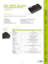
3-2.1 Control / Display Module. The Control / Display Module,
figure 3-2.1, includes the control and test switches, the solid state
logic elements, shutdown and alarm TATTLETALE
®
lights that
make up the generator engine control for a four-cycle engine.
3-2.1.1 Mode Selector Switch, OFF-AUTO-TEST:
(a) OFF; turns off the control system and resets any shutdown
circuits.
(b) AUTO; turns on the engine controls and shutdown circuits.
System is on standby waiting for a contact closure to start
engine.
(c) TEST; turns on the engine controls and shutdown circuits.
A start signal is applied to the automatic control and the
engine start sequence begins.
3-2.1.2 Lamp Test Pushbutton: Tests the lights on the A901
module.
3-2.1.3 Alarm Silence Pushbutton: Turns off any audible alarm
that is connected to the Local or Remote Audible Alarm Relays.
The indicating light will remain on as long as the condition
exists. If the Alarm Silence pushbutton is not operated, the
audible alarm will turn off when the alarm contact clears.
3-2.1.4 The A901 SELECTRONIC
®
Control Module includes
the following engine control features:
(a) Cycle crank circuit; will crank the engine for 15 seconds
then rest for 15 seconds until the engine starts. The
crank/rest time can be selected for either 10, 15, 20, 25 or
30 seconds. If the engine false starts, goes above crank
disconnect speed then drops below that speed, the control
will rest for a fixed 10 second period before cranking again.
(b) Crank Disconnect Speed Switch; this circuit detects
engine speed and terminates cranking when engine speed
rises above the speed switch setting. The speed switch is
adjustable, 25 Hz to 2000 Hz, and is factory set at 1180
Hz. This would be 600 RPM on an engine with 118 teeth
on the flywheel ring gear.
(c) Auxiliary Crank Disconnect Circuit; this circuit, required by
NFPA-110, is provided as a back up for the Crank
Disconnect Speed Switch. It is operated by an external
switch sensing either speed, generator voltage or some other
variable that could be used to terminate cranking. Either
circuit will disconnect the starter when the engine starts.
Low Water
Temperature
AUTO
OFF
TEST
Loss of Speed
Signal
Lamp Test
Water
Temperature
Low Battery
Voltage
Alarm Silence
High Battery
Voltage
Low Fuel
Level
High Water Temp.
PreAlarm
Battery Charger
AC Failure
Switch
Not In AUTO
Low Oil Pressure
PreAlarm
Oil Pressure
Overspeed
Overcrank
6-1/2 in.
(165 mm)
9-3/4 in.
(248 mm)
Figure 3-2.1
2
DISCONTINUED

Table 3-1.7
3
Level 1
C.V.
S
L.A.
R.A.
R.V.
Level 2
C.V.
S
L.A.
R.A.
R.V.
NFPA-110
NFPA99
C.V.
S
L.A.
R.A.
R.V.
②
CAN/CSA
C282-M89
C.V. S L.A. R.A. R.V.
A901
C.V.
S L.A. R.A. R.V.
A902
C.V. S L.A.
R.A.
R.V.
④ ④
A903
C.V.
S
L.A.
R.A. R.V.
④ ④
a. Overcrank X X X X X X X X O O X X X X X X X X X X X X X X X X X X O O X X X O O
b. Low Water Temperature X — X X X X — X O O X — X X X X — X X X X — X X X X — X O O X — X O O
c. High Engine Temp. Prealarm X — X X X O — O — O X — X X X O — O O O X — X X X — — — — — — X O O
d. High Engine Temperature X X X X X X X X O O X X X X X X X X X X X X X X X X X X O O X X X O O
e. Low Lube Oil Pressure Prealarm X — X X X X X O — O X — X X X O — O O O X — X X X — — — — — — X O O
f. Low Lube Oil Pressure X X X X X X X X O O X X X X X X X X X X X X X X X X X X O O X X X O O
g. Overpeed X X X X X X X X O O X X X X X X X X X X X X X X X X X X O O X X X O O
h. Low Fuel Main Tank X — X X X O — O O O X — X X X X — X X X X — X X X — — — — — — X O O
i. Control Switch not set in Auto X — X X X O — O — O — — — — — X — X X X X — X X X — — O — O — — — —
j. High Battery Voltage X — X — X O — O — O — — — — — — — — — — X — X — X — — O — O — — — —
k. Low VoltageBattery X — X — X O — O — O — — — — — X — X X X X — X — X — — O — O — — — —
l. Lamp Test X — — — X X — — — — — — — — — X — — — — X — — — — X — — — — X — — — —
m. Audible Alarm Silencing switch — — X X — — — — O — — — — — — — — X X — — — — X — — — — O — — — X O —
n. Low Starting Air Pressure X — X — X O — O — O — — — — — X — X X X — — — — — — — — — — — — — — —
o. Low Starting Hydraulic Pressure X — X — X O — O — O — — — — — X — X X X — — — — — — — — — — — — — — —
q. Remote Emergency Stop — X — — — — X — — — — — — — — — O — — — — X — — — — X — — — — X — — —
r. Low Coolant Level — — — — — — — — — — — — — — — X — X X X — — — — — — — — — — — — — — —
s. Battery Charger AC Failure X — X — X O — O — O — — — — — — — — — — X — X — X — — O — O — — — —
③③ ③③ ③
③
③
⑤
⑤
⑤
⑤
⑤
⑤
①
①
KEY
C.V.: Control panel-mounted Visual indication.
S: Shutdown of EPS
L.A.: Local Audible contacts.
R.A.: Remote Audible contacts.
R.V.: Remote Visual contacts.
X: Required
O: Optional
①: Items “N” or “O” apply only when applicable as
a starting method.
②: NFPA99 requires an audible alarm for all alarm and
shutdown functions. May be connected to L.A. contacts.
③: Air Damper Closed and is available on -2 models only.
④: R.A. and R.V. relays not supplied in model A902 or
A903, optional.
⑤: Circuits and indicators supplied without labels.
p. Air shutdown dampner when used X X X X X X X X O O — — — — — X X X — X X X X X O O X O O
DISCONTINUED

(d) Overcrank circuit; will stop automatic cranking and
indicate overcrank if engine fails to start after 3 attempts.
The number of cranks are selectable for 1, 2, 3, 4 or 5
cycles before shutdown. The overcrank circuit may also
be turned off so no overcrank shutdown occurs.
(e) Shutdown Time Delay Bypass; this delay prevents the oil
pressure, water temperature and loss of speed signal
shutdown circuits from operating for 15 seconds after the
engine starts as detected by the crank disconnect circuit.
This same delay also locks out the Low Oil Pressure Pre-
alarm and High Water Temperature Pre-alarm circuits
when the engine is not running.
(f) Overspeed Speed Switch;
1. Provides a signal to the overspeed shutdown circuit if
the engine exceeds the preset speed. The factory
setting is approximately 3894 Hz, or 1980 RPM on an
engine with 118 teeth on the flywheel ring gear. The
adjustment range is 300 Hz to 10,000 Hz.
2. A push-to-test switch is provided to allow testing of the
overspeed circuit without overspeeding the engine.
When switch is depressed, the set point of the speed
switch is lowered approximately 10%.
3. The push-to-test switch can also be used to set the
overspeed switch at approximately 110% of running
speed. Hold the switch depressed while adjusting the
setting until the overspeed trips. When switch is
released, the set point will be 10% above normal running
speed. This is the method used to make the factory
setting. With engine speed at 1800 RPM or 3540 Hz.
(g) Cooldown circuit; this circuit keeps the engine running
for five minutes after the transfer switch has removed
the load from the generator and signaled the A901 to
stop the engine. This feature may be selected (turned
On, standard setting is Off) with a switch on the back of
the Control / Display Module.
3-2.1.5 Seven (7) First-out Shutdown Circuits; provide first-out
indication of cause of shutdown. These circuits deactivate the
fuel relay and lockout the A901 until reset. Shutdown circuits
are activated by the crank disconnect circuit and are not active
when the engine is stopped. Six (6) Red Shutdown Indicating
Lights are provided. The Remote Shutdown circuit does not
have an indicator light.
(a) Overcrank; tripped by the overcrank sensing circuit which
counts the number of cranking attempts.
(b) Overspeed; tripped by overspeed switch when engine
exceeds a preset speed.
(c) Oil Pressure; tripped by the oil pressure SWICHGAGE
®
if pressure drops below preset point while the engine is
running.
(d) Water Temperature; tripped by the water temperature
SWICHGAGE
®
if engine coolant temperature exceeds the
switch setting.
(e) Spare Shutdown; tripped by an external switch. This
circuit is provided for an additional shutdown that may be
recommended by the engine supplier.
(f) Loss of Speed Signal; tripped by an internal sensing
circuit that detects the loss of the Magnetic Pickup
frequency signal for the speed switches while the engine
is still running. Since the Overspeed shutdown circuit is
activated by the frequency input, it prevents the engine
from running without overspeed protection.
(g) Remote Shutdown; this circuit is provided to shutdown
the engine generator from a remote location. No
indicating light is provided.
3-2.1.6 Nine (9) Alarm Indicating Circuits; provide indication of
cause of alarm. These circuits activate the alarm relays. Alarm
circuits are active as long as power is applied to the A901. All are
active when the engine is running, shutdown or on standby except
Low Oil Pressure Pre- alarm and High Water Temperature Pre-
alarm. Nine (9) Amber Alarm Indicating Lights are provided.
(a) Low Water Temperature; operated by low water temp-
erature SWICHGAGE
®
.
(b) Spare Alarm; operated by an external switch. This circuit
is provided for an additional alarm that may be required by
the user.
(c) Switch Not In Automatic; operated by the OFF-AUTO-
TEST mode selector switch.
(d) Low Fuel Level; operated by level switch on fuel tank.
(e) High Battery Voltage; operated by relay contact in
battery charger.
(f) Low Battery Voltage; operated by low voltage sensing
device in battery charger.
(g) Low Oil Pressure Pre-alarm; operated by pre-alarm
switch in oil pressure SWICHGAGE
®
.
(h) High Water Temperature Pre-alarm; operated by pre
alarm switch in water temperature SWICHGAGE
®
.
(i) Battery Charger AC Failure: operated by a relay contact in
the Battery Charger.
3-2.2 Relay Module. The Relay Module, figure 3-2.2, includes
all of the control, alarm and shutdown relays that are required to
make up the generator engine control. Relays are available for
operation on either 12 or 24 volt battery systems. Five (5) relays
are included for:
3-2.2.1 Fuel Relay; this relay provides two outputs, one to
energize the engine fuel solenoid and a separate circuit to
4
DC12V
3A Fuse
1A
4
5
6
7
8
9
16
17
18
19
20
21
22
23
24
25
RH2V2
-U
DC12V
RH2V2
-U
DC12V
RH2V2
-U
DC12V
RH2V2
-U
DC12V
RH2V2
-U
6-1/4 in.
(159 mm)
4-1/2 in.
(114 mm)
Figure 3-2.2
DISCONTINUED

energize the battery charging alternator field.
3-2.2.2 Shutdown Relay; this relay is operated by the shutdown
circuits of the Control / Display Module and provides an output
that can be used to trip the generator circuit breaker on an
emergency shutdown.
3-2.2.3 Local Audible Alarm Relay; provides a contact closure
to operate a local audible alarm as required by NFPA-110, Level
1 and Level 2.
3-2.2.4 Remote Audible Alarm Relay; provides a contact
closure to operate a remote audible alarm as required by NFPA-
110, Level 1.
3-2.2.5 Remote Visual Alarm Relay; provides a contact closure
to operate a remote visual alarm as required by NFPA- 110,
Level 1.
3-2.3 Status Signals. The relay module also includes three
outputs that can be used with external circuits for signaling or
control functions.
3-2.3.1 The Control On function at terminal 12 is on (closed
to negative) as long as the Mode Selector Switch is in either
Auto or Test. When the Mode Selector is turned Off, the
Control On signal is open. This can be used to signal switch
position or to reset an external circuit when the Mode Selector
is turned Off.
3-2.3.2 The System Ready signal at terminal 13 is on (closed
to negative) as long as the Mode Selector Switch is in either
Auto or Test and no shutdown Tattletale circuit is latched on.
This can be used to signal that the generator engine is ready to
automatically start or is running in Test.
3-2.3.3 The Control On function at terminal 14 is on (closed
to positive) as long as the Mode Selector Switch is in either
Auto or Test. When the Mode Selector is turned Off, the
Control On signal is open. This can be used to signal switch
position or to reset an external circuit when the Mode Selector
is turned Off.
3-3 A901-2.
3-3.1 Control / Display Module. The Control / Display Module,
figure 3-3.1, includes the control and test switches, the solid state
logic elements, shutdown and alarm TATTLETALE
®
lights that
make up the generator engine control for a two-cycle engine.
3-3.1.1 Mode Selector Switch, OFF-AUTO-TEST:
(a) OFF; turns off the control system and resets any shutdown
circuits.
(b) AUTO; turns on the engine controls and shutdown
circuits. System is on standby waiting for a contact
closure to start engine.
(c) TEST; turns on the engine controls and shutdown circuits.
A start signal is applied to the automatic control and the
engine start sequence begins.
3-3.1.2 Lamp Test Pushbutton: Tests the lights on the A- 901-2
module.
3-3.1.3 Alarm Silence Pushbutton: Turns off any audible alarm
that is connected to the Local or Remote Audible Alarm Relays.
The indicating light will remain on as long as the condition
exists. If the Alarm Silence pushbutton is not operated, the
audible alarm will turn off when the alarm contact clears.
3-3.1.4 The A901-2 SELECTRONIC
®
Control Module includes
the following engine control features:
(a) Cycle crank circuit; will crank the engine for 15 seconds
then rest for 15 seconds until the engine starts. The
crank/rest time is selectable for either 10, 15, 20, 25 or 30
seconds. If the engine false starts, goes above crank
disconnect speed then drops below that speed, the control
will rest for a fixed 10 second period before cranking again.
(b) Crank Disconnect Speed Switch; this circuit detects
engine speed and terminates cranking when engine speed
rises above the speed switch setting. The speed switch is
adjustable, 25 Hz to 2000 Hz, and is factory set at 1180
Hz. This would be 600 RPM on an engine with 118 teeth
on the flywheel ring gear.
(c) Auxiliary Crank Disconnect Circuit; this circuit, required by
NFPA-110, is provided as a back up for the Crank Discon-
nect Speed Switch. It is operated by an external switch
sensing either speed, generator voltage or some other
variable that could be used to terminate cranking. Either
circuit will disconnect the starter when the engine starts.
(d) Overcrank circuit; will stop automatic cranking and
indicate overcrank if engine fails to start after 3 attempts.
The number of cranks are selectable for 1, 2, 3, 4 or 5
cycles before shutdown. The overcrank circuit may also
be turned off so no overcrank shutdown occurs.
(e) Shutdown Time Delay Bypass; this delay prevents the oil
pressure, water temperature and loss of speed signal
shutdown circuits from operating for 15 seconds after the
engine starts as detected by the crank disconnect circuit.
This same delay also locks out the Low Oil Pressure Pre-
alarm and High Water Temperature Pre-alarm circuits
when the engine is not running.
Low Water
Temperature
AUTO
OFF
TEST
Loss of Speed
Signal
Lamp Test
Water
Temperature
Air Damper
Closed
Low Battery
Voltage
Alarm Silence
Battery Charger
AC Failure
High Battery
Voltage
Low Fuel
Level
High Water Temp.
PreAlarm
Switch
Not In AUTO
Low Oil Pressure
PreAlarm
Oil Pressure
Overspeed
Overcrank
6-1/2 in.
(165 mm)
9-3/4 in.
(248 mm)
Figure 3-3.1
5
DISCONTINUED

(f) Overspeed Speed Switch;
1. Provides a signal to the overspeed shutdown circuit if
the engine exceeds the preset speed. The factory
setting is approximately 3894 Hz, or 1980 RPM on an
engine with 118 teeth on the flywheel ring gear. The
adjustment range is 300 Hz to 10,000 Hz.
2. A push to test switch is provided to allow testing of the
overspeed circuit without overspeeding the engine.
When switch is depressed, the set point of the speed
switch is lowered approximately 10%.
3. The push to test switch can also be used to set the
overspeed switch at approximately 110% of running
speed. Hold the switch depressed while adjusting the
setting until the overspeed trips. When switch is
released, the set point will be 10% above normal running
speed. This is the method used to make the factory
setting. With engine speed at 1800 RPM or 3540 Hz.
(g) Cooldown circuit; this circuit keeps the engine running
for five minutes after the transfer switch has removed
the load from the generator and signaled the A901-2 to
stop the engine. This feature may be selected (turned
On, standard setting is Off) with a switch on the back of
the Control / Display Module.
3-3.1.5 Seven (7) First-out Shutdown Circuits; provide first-out
indication of cause of shutdown. These circuits deactivate the
fuel relay and lockout the A901-2 until reset. Shutdown circuits
are activated by the crank disconnect circuit and are not active
when the engine is stopped. Six (6) Red Shutdown Indicating
Lights are provided. The Remote Shutdown circuit does not
have an indicator light.
(a) Overcrank; tripped by the overcrank sensing circuit which
counts the number of cranking attempts.
(b) Overspeed; tripped by overspeed switch when engine
exceeds a preset speed.
(c) Oil Pressure; tripped by the oil pressure SWICHGAGE
®
if
pressure drops below preset point while the engine is running.
(d) Water Temperature; tripped by the water temperature
SWICHGAGE
®
if engine coolant temperature exceeds the
switch setting.
(e) Spare Shutdown; tripped by an external switch. This
circuit is provided for an additional shutdown that may be
recommended by the engine supplier.
(f) Loss of Speed Signal; tripped by an internal sensing
circuit that detects the loss of the Magnetic Pickup
frequency signal for the speed switches while the engine
is still running. Since the Overspeed shutdown circuit is
activated by the frequency input, it prevents the engine
from running without overspeed protection.
(g) Remote Shutdown; this circuit is provided to shutdown
the engine generator from a remote location. No
indicating light is provided.
3-3.1.6 Nine (9) Alarm Indicating Circuits; provide indication
of cause of alarm. These circuits activate the alarm relays.
Alarm circuits are active as long as power is applied to the
A901-2. All are active when the engine is running, shutdown or
on standby except Low Oil Pressure Pre- alarm and High Water
Temperature Pre-alarm. Nine (9) Amber Alarm Indicating
Lights are provided.
(a) Low Water Temperature; operated by low water temp-
erature SWICHGAGE
®
.
(b) Air Damper Closed; operated by an external switch or by
the Overspeed Relay circuit. This circuit is provided with
a selector switch to allow the user to determine the source
of the signal.
(c) Switch Not In Automatic; operated by the OFF-AUTO-
TEST mode selector switch.
(d) Low Fuel Level; operated by level switch on fuel tank.
(e) High Battery Voltage; operated by relay contact in battery
charger.
(f) Low Battery Voltage; operated by low voltage sensing
device in battery charger.
(g)Low Oil Pressure Pre-alarm; operated by pre-alarm
switch in oil pressure SWICHGAGE
®
.
(h) High Water Temperature Pre-alarm; operated by pre-
alarm switch in water temperature SWICHGAGE
®
.
(i) Battery Charger AC Failure; operated by relay contact in
Battery Charger.
3-3.2 Relay Module. The Relay Module, figure 3-3.2, includes
all of the control, alarm and shutdown relays that are required to
make up the generator engine control. Relays are available for
operation on either 12 or 24 volt battery systems. Six (6) relays
are included for:
3-3.2.1 Fuel Relay; this relay provides two outputs, one to
energize the engine fuel solenoid and a separate circuit to
energize the battery charging alternator field.
3-3.2.2 Shutdown Relay; this relay is operated by the shutdown
circuits of the Control / Display Module and provides an output
that can be used to trip the generator circuit breaker on an
emergency shutdown.
3-3.2.3 Overspeed Relay; operates only on an Overspeed
shutdown. This relay provides an output to trip an air shut off
solenoid to close the air damper on a two-cycle engine.
3-3.2.4 Local Audible Alarm Relay; provides a contact closure
DC12V
3A Fuse
1A
4
5
6
7
8
9
16
17
18
19
20
21
22
23
24
25
DC12V
DC12V DC12V
DC12V DC12V
6-1/4 in.
(159 mm)
4-1/2 in.
(114 mm)
Figure 3-3.2
6
DISCONTINUED

7
to operate a local audible alarm as required by NFPA- 110,
Level 1 and Level 2.
3-3.2.5 Remote Audible Alarm Relay; provides a contact
closure to operate a remote audible alarm as required by NFPA-
110, Level 1.
3-3.2.6 Remote Visual Alarm Relay; provides a contact closure
to operate a remote visual alarm as required by NFPA- 110,
Level 1.
3-3.3 Status Signals. The relay module also includes three
outputs that can be used with external circuits for signaling or
control functions.
3-3.3.1 The Control On function at terminal 12 is on (closed
to negative) as long as the Mode Selector Switch is in either
Auto or Test. When the Mode Selector is turned Off, the
Control On signal is open. This can be used to signal switch
position or to reset an external circuit when the Mode Selector
is turned Off.
3-3.3.2 The System Ready signal at terminal 13 is on (closed
to negative) as long as the Mode Selector Switch is in either
Auto or Test and no shutdown Tattletale circuit is latched on.
This can be used to signal that the generator engine is ready to
automatically start or is running in Test.
3-3.3.3 The Control On function at terminal 14 is on (closed
to positive) as long as the Mode Selector Switch is in either
Auto or Test. When the Mode Selector is turned Off, the
Control On signal is open. This can be used to signal switch
position or to reset an external circuit when the Mode Selector
is turned Off.
3-4 A902.
3-4.1 Control / Display Module. The Control / Display
Module, figure 3-4.1, includes the control and test switches, the
solid state logic elements, shutdown and alarm TATTLETALE
®
lights that make up the generator engine control for a four-cycle
engine.
3-4.1.1 Mode Selector Switch, OFF-AUTO-TEST:
(a) OFF; turns off the control system and resets any shutdown
circuits.
(b) AUTO; turns on the engine controls and shutdown
circuits. System is on standby waiting for a contact
closure to start engine.
(c) TEST; turns on the engine controls and shutdown circuits.
A start signal is applied to the automatic control and the
engine start sequence begins.
3-4.1.2 Lamp Test Pushbutton: Tests the lights on the A902
module.
3-4.1.3 The A902 SELECTRONIC
®
Control Module includes
the following engine control features:
(a) Cycle crank circuit; will crank the engine for 15 seconds
then rest for 15 seconds until the engine starts. The
crank/rest time is selectable for either 10, 15, 20, 25 or 30
seconds. If the engine false starts, goes above crank
disconnect speed then drops below that speed, the control
will rest for a fixed 10 second period before cranking
again.
(b) Crank Disconnect Speed Switch; this circuit detects
engine speed and terminates cranking when engine speed
rises above the speed switch setting. The speed switch is
adjustable, 25 Hz to 2000 Hz, and is factory set at 1180
Hz. This would be 600 RPM on an engine with 118 teeth
on the flywheel ring gear.
(c) Auxiliary Crank Disconnect Circuit; this circuit, required
by NFPA-110, is provided as a back up for the Crank
Disconnect Speed Switch. It is operated by an external
switch sensing either speed, generator voltage or some
other variable that could be used to terminate cranking.
Either circuit will disconnect the starter when the engine
starts.
(d) Overcrank circuit; will stop automatic cranking and
indicate overcrank if engine fails to start after 3 attempts.
The number of cranks are selectable for 1, 2, 3, 4 or 5
cycles before shutdown. The overcrank circuit may also
be turned off so no overcrank shutdown occurs.
(e) Shutdown Time Delay Bypass; this delay prevents the oil
pressure, water temperature and loss of speed signal
shutdown circuits from operating for 15 seconds after the
engine starts as detected by the crank disconnect circuit.
(f) Overspeed Speed Switch;
1. Provides a signal to the overspeed shutdown circuit if
the engine exceeds the preset speed. The factory
setting is approximately 3894 Hz, or 1980 RPM on an
engine with 118 teeth on the flywheel ring gear. The
adjustment range is 300 Hz to 10,000 Hz.
2. A push to test switch is provided to allow testing of the
overspeed circuit without overspeeding the engine.
When switch is depressed, the set point of the speed
switch is lowered approximately 10%.
3. The push to test switch can also be used to set the
overspeed switch at approximately 110% of running
speed. Hold the switch depressed while adjusting the
Low Water
Temperature
AUTO
OFF
TEST
Loss of Speed
Signal
Lamp Test
Water
Temperature
Oil Pressure
Overspeed
Overcrank
6-1/2 in.
(165 mm)
9-3/4 in.
(248 mm)
Figure 3-4.1
DISCONTINUED

8
setting until the overspeed trips. When switch is
released, the set point will be 10% above normal
running speed. This is the method used to make the
factory setting. With engine speed at 1800 RPM or
3540 Hz.
(g) Cooldown circuit; this circuit keeps the engine running
for five minutes after the transfer switch has removed the
load from the generator and signaled the A902 to stop
the engine. This feature may be selected (turned On,
standard setting is Off) with a switch on the back of the
Control / Display Module.
3-4.1.4 Seven (7) First-out Shutdown Circuits; provide first-out
indication of cause of shutdown. These circuits deactivate the
fuel relay and lockout the A902 until reset. Shutdown circuits
are activated by the crank disconnect circuit and are not active
when the engine is stopped. Six (6) Red Shutdown Indicating
Lights are provided. The Remote Shutdown circuit does not
have an indicator light.
(a) Overcrank; tripped by the overcrank sensing circuit which
counts the number of cranking attempts.
(b) Overspeed; tripped by overspeed switch when engine
exceeds a preset speed.
(c) Oil Pressure; tripped by the oil pressure SWICHGAGE
®
if
pressure drops below preset point while the engine is
running.
(d) Water Temperature; tripped by the water temperature
SWICHGAGE
®
if engine coolant temperature exceeds the
switch setting.
(e) Spare Shutdown; tripped by an external switch. This
circuit is provided for an additional shutdown that may be
recommended by the engine supplier.
(f) Loss of Speed Signal; tripped by an internal sensing
circuit that detects the loss of the Magnetic Pickup
frequency signal for the speed switches while the engine
is still running. Since the Overspeed shutdown circuit is
activated by the frequency input, it prevents the engine
from running without overspeed protection.
(g) Remote Shutdown; this circuit is provided to shutdown
the engine generator from a remote location. No
indicating light is provided.
3-4.1.5 Two (2) Alarm Indicating Circuits; provide indication
of cause of alarm. These circuits activate the alarm relay. Alarm
circuits are active as long as power is applied to the A902. All
are active when the engine is running, shutdown or on standby.
Two (2) Amber Alarm Indicating Lights are provided.
(a) Low Water Temperature; operated by low water
temperature SWICHGAGE
®
.
(b) Spare Alarm; operated by an external switch. This circuit
is provided for an additional alarm that may be required
by the user.
3-4.2 Relay Module. The Relay Module, figure 3-4.2, includes
all of the control, alarm and shutdown relays that are required to
make up the generator engine control. Relays are available for
operation on either 12 or 24 volt battery systems. Three (3)
relays are included for:
3-4.2.1 Fuel Relay; this relay provides two outputs, one to
energize the engine fuel solenoid and a separate circuit to
energize the battery charging alternator field.
3-4.2.2 Shutdown Relay; this relay is operated by the shutdown
circuits of the Control / Display Module and provides an output
that can be used to trip the generator circuit breaker on an
emergency shutdown.
3-4.2.3 Local Audible Alarm Relay; provides a contact closure
to operate a local audible alarm as required by NFPA- 110, Level
1 and Level 2.
3-4.3 Status Signals. The relay module also includes three
outputs that can be used with external circuits for signaling or
control functions.
3-4.3.1 The Control On function at terminal 12 is on (closed to
negative) as long as the Mode Selector Switch is in either Auto
or Test. When the Mode Selector is turned Off, the Control On
signal is open. This can be used to signal switch position or to
reset an external circuit when the Mode Selector is turned Off.
3-4.3.2 The System Ready signal at terminal 13 is on (closed
to negative) as long as the Mode Selector Switch is in either
Auto or Test and no shutdown TATTLETALE
®
circuit is
latched on. This can be used to signal that the generator engine
is ready to automatically start or is running in Test.
3-4.3.3 The Control On function at terminal 14 is on (closed to
positive) as long as the Mode Selector Switch is in either Auto
or Test. When the Mode Selector is turned Off, the Control On
signal is open. This can be used to signal switch position or to
reset an external circuit when the Mode Selector is turned Off.
3-5 A902-2.
3-5.1 Control / Display Module. The Control / Display Module,
figure 3-5.1, includes the control and test switches, the solid state
logic elements, shutdown and alarm TATTLETALE
®
lights that
make up the generator engine control for a two-cycle engine.
3-5.1.1 Mode Selector Switch, OFF-AUTO-TEST:
(a) OFF; turns off the control system and resets any shutdown
circuits.
(b) AUTO; turns on the engine controls and shutdown circuits.
System is on standby waiting for a contact closure to start
engine.
DC12V
3A Fuse
1A
4
5
6
7
8
9
16
17
18
19
20
21
22
23
24
25
DC12V
DC12V
6-1/4 in.
(159 mm)
4-1/2 in.
(114 mm)
Figure 3-4.2
DISCONTINUED

9
(c) TEST; turns on the engine controls and shutdown circuits.
A start signal is applied to the automatic control and the
engine start sequence begins.
3-5.1.2 Lamp Test Pushbutton: Tests the lights on the A- 902-2
module.
3-5.1.3 The A902-2 SELECTRONIC
®
Control Module includes
the following engine control features:
(a) Cycle crank circuit; will crank the engine for 15 seconds
then rest for 15 seconds until the engine starts. The
crank/rest time is selectable for either 10, 15, 20, 25 or 30
seconds. If the engine false starts, goes above crank
disconnect speed then drops below that speed, the control
will rest for a fixed 10 second period before cranking
again.
(b) Crank Disconnect Speed Switch; this circuit detects
engine speed and terminates cranking when engine speed
rise above the speed switch setting. The speed switch is
adjustable, 25 Hz to 2000 Hz, and is factory set at 1180
Hz. This would be 600 RPM on an engine with 118 teeth
on the flywheel ring gear.
(c) Auxiliary Crank Disconnect Circuit; this circuit, required
by NFPA-110, is provided as a back up for the Crank
Disconnect Speed Switch. It is operated by an external
switch sensing either speed, generator voltage or some
other variable that could be used to terminate cranking.
Either circuit will disconnect the starter when the engine
starts.
(d) Overcrank circuit; will stop automatic cranking and
indicate overcrank if engine fails to start after 3 attempts.
The number of cranks are selectable for 1, 2, 3, 4 or 5
cycles before shutdown. The overcrank circuit may also
be turned off so no overcrank shutdown occurs.
(e) Shutdown Time Delay Bypass; this delay prevents the oil
pressure, water temperature and loss of speed signal
shutdown circuits from operating for 15 seconds after the
engine starts as detected by the crank disconnect circuit.
(f) Overspeed Speed Switch;
1. Provides a signal to the overspeed shutdown circuit if
the engine exceeds the preset speed. The factory
setting is approximately 3894 Hz, or 1980 RPM on an
engine with 118 teeth on the flywheel ring gear. The
adjustment range is 300 Hz to 10,000 Hz.
2. A push to test switch is provided to allow testing of the
overspeed circuit without overspeeding the engine.
When switch is depressed, the set point of the speed
switch is lowered approximately 10%.
3. The push to test switch can also be used to set the
overspeed switch at approximately 110% of running
speed. Hold the switch depressed while adjusting the
setting until the overspeed trips. When switch is
released, the set point will be 10% above normal
running speed. This is the method used to make the
factory setting. With engine speed at 1800 RPM or
3540 Hz.
(g) Cooldown circuit; this circuit keeps the engine running
for five minutes after the transfer switch has removed
the load from the generator and signaled the A902-2 to
stop the engine. This feature may be selected (turned
On, standard setting is Off) with a switch on the back of
the Control / Display Module.
3-5.1.4 Seven (7) First-out Shutdown Circuits; provide first-out
indication of cause of shutdown. These circuits deactivate the
fuel relay and lockout the A902-2 until reset. Shutdown circuits
are activated by the crank disconnect circuit and are not active
when the engine is stopped. Six (6) Red Shutdown Indicating
Lights are provided. The Remote Shutdown circuit does not
have an indicator light.
(a) Overcrank; tripped by the overcrank sensing circuit which
counts the number of cranking attempts.
(b) Overspeed; tripped by overspeed switch when engine
exceeds a preset speed.
(c) Oil Pressure; tripped by the oil pressure SWICHGAGE
®
if pressure drops below preset point while the engine is
running.
(d) Water Temperature; tripped by the water temperature
SWICHGAGE
®
if engine coolant temperature exceeds the
switch setting.
(e) Spare Shutdown; tripped by an external switch. This
circuit is provided for an additional shutdown that may be
recommended by the engine supplier.
(f) Loss of Speed Signal; tripped by an internal sensing
circuit that detects the loss of the Magnetic Pickup
frequency signal for the speed switches while the engine
is still running. Since the Overspeed shutdown circuit is
activated by the frequency input, it prevents the engine
from running without overspeed protection.
(g) Remote Shutdown; this circuit is provided to shutdown
the engine generator from a remote location. No
indicating light is provided.
3-5.1.5 Two (2) Alarm Indicating Circuits; provide indication
Low Water
Temperature
AUTO
OFF
TEST
Loss of Speed
Signal
Lamp Test
Water
Temperature
Air Damper
Closed
Oil Pressure
Overspeed
Overcrank
6-1/2 in.
(165 mm)
9-3/4 in.
(248 mm)
Figure 3-5.1
DISCONTINUED

of cause of alarm. These circuits activate the alarm relay.
Alarm circuits are active as long as power is applied to the
A902-2. All are active when the engine is running, shutdown or
on standby. Two (2) Amber Alarm Indicating Lights are
provided.
(a) Low Water Temperature; operated by low water
temperature SWICHGAGE
®
.
(b) Air Damper Closed; operated by an external switch or by
the Overspeed Relay circuit. This circuit is provided with
a selector switch to allow the user to determine the source
of the signal.
3-5.2 Relay Module. The Relay Module, figure 3-5.2, includes
all of the control, alarm and shutdown relays that are required to
make up the generator engine control. Relays are available for
operation on either 12 or 24 volt battery systems. Four (4)
relays are included for:
3-5.2.1 Fuel Relay; this relay provides two outputs, one to
energize the engine fuel solenoid and a separate circuit to
energize the battery charging alternator field.
3-5.2.2 Shutdown Relay; this relay is operated by the shutdown
circuits of the Control / Display Module and provides an output
that can be used to trip the generator circuit breaker on an
emergency shutdown.
3-5.2.3 Overspeed Relay; operates only on an Overspeed
shutdown. This relay provides an output to trip an air shut off
solenoid to close the air damper on a two-cycle engine.
3-5.2.4 Local Audible Alarm Relay; provides a contact closure
to operate a local audible alarm as required by NFPA- 110, Level
1 and Level 2.
3-5.3 Status Signals. The relay module also includes three
outputs that can be used with external circuits for signaling or
control functions.
3-5.3.1 The Control On function at terminal 12 is on (closed to
negative) as long as the Mode Selector Switch is in either Auto
or Test. When the Mode Selector is turned Off, the Control On
signal is open. This can be used to signal switch position or to
reset an external circuit when the Mode Selector is turned Off.
3-5.3.2 The System Ready signal at terminal 13 is on (closed
to negative) as long as the Mode Selector Switch is in either
Auto or Test and no shutdown TATTLETALE
®
circuit is
latched on. This can be used to signal that the generator
engine is ready to automatically start or is running in Test.
3-5.3.3 The Control On function at terminal 14 is on (closed to
positive) as long as the Mode Selector Switch is in either Auto
or Test. When the Mode Selector is turned Off, the Control On
signal is open. This can be used to signal switch position or to
reset an external circuit when the Mode Selector is turned Off.
3-6 A903.
3-6.1 Control / Display Module. The Control / Display Module,
figure 3-6.1, includes the control and test switches, the solid
state logic elements, shutdown and alarm TATTLETALE
®
lights
that make up the generator engine control for a four cycle
engine. This module is the same as Model A- 901 except 7 of
the alarm circuits are un-labeled. This allows the customer to
specify labels other than those recommended in NFPA-110.
This model has shutdown and alarm circuits labeled to meet the
requirements of NFPA-110, Level 2.
3-6.1.1 Mode Selector Switch, OFF-AUTO-TEST:
(a) OFF; turns off the control system and resets any shutdown
circuits.
(b) AUTO; turns on the engine controls and shutdown circuits.
System is on standby waiting for a contact closure to start
engine.
(c) TEST; turns on the engine controls and shutdown circuits.
A start signal is applied to the automatic control and the
engine start sequence begins.
Figure 3-6.1
10
DC12V
3A Fuse
1A
4
5
6
7
8
9
16
17
18
19
20
21
22
23
24
25
DC12V
DC12V
DC12V
6-1/4 in.
(159 mm)
4-1/2 in.
(114 mm)
Figure 3-5.2
DISCONTINUED

3-6.1.2 Lamp Test Pushbutton: Tests the lights on the A903
module.
3-6.1.3 Alarm Silence Pushbutton: Turns off any audible alarm
that is connected to the Local or Remote Audible Alarm Relays.
The indicating light will remain on as long as the condition
exists. If the Alarm Silence pushbutton is not operated, the
audible alarm will turn off when the alarm contact clears.
3-6.1.4 The A903 SELECTRONIC
®
Control Module includes
the following engine control features:
(a) Cycle crank circuit; will crank the engine for 15 seconds
then rest for 15 seconds until the engine starts. The
crank/rest time is selectable for either 10, 15, 20, 25 or 30
seconds. If the engine false starts, goes above crank
disconnect speed then drops below that speed, the control
will rest for a fixed 10 second period before cranking
again.
(b) Crank Disconnect Speed Switch; this circuit detects
engine speed and terminates cranking when engine speed
rises above the speed switch setting. The speed switch is
adjustable, 25 Hz to 2000 Hz, and is factory set at 1180
Hz. This would be 600 RPM on an engine with 118 teeth
on the flywheel ring gear.
(c) Auxiliary Crank Disconnect Circuit; this circuit, required
by NFPA-110, is provided as a back up for the Crank
Disconnect Speed Switch. It is operated by an external
switch sensing either speed, generator voltage or some
other variable that could be used to terminate cranking.
Either circuit will disconnect the starter when the engine
starts.
(d) Overcrank circuit; will stop automatic cranking and
indicate overcrank if engine fails to start after 3 attempts.
The number of cranks are selectable for 1, 2, 3, 4 or 5
cycles before shutdown. The overcrank circuit may also
be turned off so no overcrank shutdown occurs.
(e) Shutdown Time Delay Bypass; this delay prevents the oil
pressure, water temperature and loss of speed signal
shutdown circuits from operating for 15 seconds after the
engine starts as detected by the crank disconnect circuit.
This same delay also locks out alarm circuit #7 and #8
when the engine is not running.
(f) Overspeed Speed Switch;
1. Provides a signal to the overspeed shutdown circuit if
the engine exceeds the preset speed. The factory
setting is approximately 3894 Hz, or 1980 RPM on an
engine with 118 teeth on the flywheel ring gear. The
adjustment range is 300 Hz to 10,000 Hz.
2. A push to test switch is provided to allow testing of
the overspeed circuit without overspeeding the
engine. When switch is depressed, the set point of the
speed switch is lowered approximately 10%.
3. The push to test switch can also be used to set the
overspeed switch at approximately 110% of running
speed. Hold the switch depressed while adjusting the
setting until the overspeed trips. When switch is
released, the set point will be 10% above normal
running speed. This is the method used to make the
factory setting. With engine speed at 1800 RPM or
3540 Hz.
(g) Cooldown circuit; this circuit keeps the engine running
for five minutes after the transfer switch has removed
the load from the generator and signaled the A903 to
stop the engine. This feature may be selected (turned
On, standard setting is Off) with a switch on the back of
the Control / Display Module.
3-6.1.5 Seven (7) First-out Shutdown Circuits; provide first-
out indication of cause of shutdown. These circuits deactivate
the fuel relay and lockout the A903 until reset. Shutdown
circuits are activated by the crank disconnect circuit and are not
active when the engine is stopped. Six (6) Red Shutdown
Indicating Lights are provided. The Remote Shutdown circuit
does not have an indicator light.
(a) Overcrank; tripped by the overcrank sensing circuit
which counts the number of cranking attempts.
(b) Overspeed; tripped by overspeed switch when engine
exceeds a preset speed.
(c) Oil Pressure; tripped by the oil pressure SWICHGAGE
®
if pressure drops below preset point while the engine is
running.
(d) Water Temperature; tripped by the water temperature
SWICHGAGE
®
if engine coolant temperature exceeds
the switch setting.
(e) Spare Shutdown; tripped by an external switch. This
circuit is provided for an additional shutdown that may
be recommended by the engine supplier.
(f) Loss of Speed Signal; tripped by an internal sensing
circuit that detects the loss of the Magnetic Pickup
frequency signal for the speed switches while the engine
is still running. Since the Overspeed shutdown circuit is
activated by the frequency input, it prevents the engine
from running without overspeed protection.
(g) Remote Shutdown; this circuit is provided to shutdown
the engine generator from a remote location. No
indicating light is provided.
3-6.1.6 Nine (9) Alarm Indicating Circuits; provide indication
of cause of alarm. These circuits activate the alarm relays.
Alarm circuits are active as long as power is applied to the
A903. All are active when the engine is running, shutdown or
on standby except alarm circuit #7 and #8 which are locked out
until the engine is running. Nine (9) Amber Alarm Indicating
Lights are provided however only two circuits are labeled. The
other 7 are for customer specified alarms.
(a) Low Water Temperature; operated by low water
temperature SWICHGAGE
®
.
(b) #2 Spare Alarm; operated by an external switch. This
circuit is provided for an additional alarm that may be
required by the user.
(c) Switch Not In Automatic; operated by the OFF-AUTO-
TEST mode selector switch.
(d) #4 Spare Alarm; operated by an external switch. This
circuit is provided for an additional alarm that may be
required by the user.
(e) #5 Spare Alarm; operated by an external switch. This
circuit is provided for an additional alarm that may be
required by the user.
(f) #6 Spare Alarm; operated by an external switch. This
circuit is provided for an additional alarm that may be
required by the user.
(g) #7 Spare Alarm; operated by an external switch. This
circuit is provided for an additional alarm that may be
required by the user.
11
DISCONTINUED

(h) #8 Spare Alarm; operated by an external switch. This
circuit is provided for an additional alarm that may be
required by the user.
(i) #9 Spare Alarm; operated by an external switch. This
circuit is provided for an additional alarm that may be
required by the user.
3-6.2 Relay Module. The Relay Module, figure 3-6.2, includes
all of the control, alarm and shutdown relays that are required to
make up the generator engine control. Relays are available for
operation on either 12 or 24 volt battery systems. Three (3)
relays are included for:
3-6.2.1 Fuel Relay; this relay provides two outputs, one to
energize the engine fuel solenoid and a separate circuit to
energize the battery charging alternator field.
3-6.2.2 Shutdown Relay; this relay is operated by the shutdown
circuits of the Control / Display Module and provides an output
that can be used to trip the generator circuit breaker on an
emergency shutdown.
3-6.2.3 Local Audible Alarm Relay; provides a contact closure
to operate a local audible alarm as required by NFPA- 110, Level
1 and Level 2.
3-6.3 Status Signals. The relay module also includes three
outputs that can be used with external circuits for signaling or
control functions.
3-6.3.1 The Control On function at terminal 12 is on (closed to
negative) as long as the Mode Selector Switch is in either Auto
or Test. When the Mode Selector is turned Off, the Control On
signal is open. This can be used to signal switch position or to
reset an external circuit when the Mode Selector is turned Off.
3-6.3.2 The System Ready signal at terminal 13 is on (closed
to negative) as long as the Mode Selector Switch is in either
Auto or Test and no shutdown TATTLETALE
®
circuit is
latched on. This can be used to signal that the generator
engine is ready to automatically start or is running in Test.
3-6.3.3 The Control On function at terminal 14 is on (closed to
positive) as long as the Mode Selector Switch is in either Auto
or Test. When the Mode Selector is turned Off, the Control On
signal is open. This can be used to signal switch position or to
reset an external circuit when the Mode Selector is turned Off.
3-7 A903-2.
3-7.1 Control / Display Module. The Control / Display Module,
figure 3-7.1, includes the control and test switches, the solid
state logic elements, shutdown and alarm TATTLETALE
®
lights
that make up the generator engine control for a two-cycle
engine. This module is the same as Model A901-2 except 6 of
the alarm circuits are un-labeled. This allows the customer to
specify labels other than those recommended in NFPA-110.
This model has shutdown and alarm circuits labeled to meet the
requirements of NFPA-110, Level 2.
3-7.1.1 Mode Selector Switch, OFF-AUTO-TEST:
(a) OFF; turns off the control system and resets any shutdown
circuits.
(b) AUTO; turns on the engine controls and shutdown
circuits. System is on standby waiting for a contact
closure to start engine.
(c) TEST; turns on the engine controls and shutdown circuits.
A start signal is applied to the automatic control and the
engine start sequence begins.
3-7.1.2 Lamp Test Pushbutton: Tests the lights on the A- 903-2
module.
3-7.1.3 Alarm Silence Pushbutton: Turns off any audible alarm
that is connected to the Local or Remote Audible Alarm Relays.
The indicating light will remain on as long as the condition
exists. If the Alarm Silence pushbutton is not operated, the
Figure 3-7.1
12
DC24V
3A Fuse
1A
4
5
6
7
8
9
16
17
18
19
20
21
22
23
24
25
DC24V
DC24V
6-1/4 in.
(159 mm)
4-1/2 in.
(114 mm)
Figure 3-6.2
DISCONTINUED

audible alarm will turn off when the alarm contact clears.
3-7.1.4 The A903-2 SELECTRONIC
®
Control Module includes
the following engine control features:
(a) Cycle crank circuit; will crank the engine for 15 seconds
then rest for 15 seconds until the engine starts. The
crank/rest time is selectable for either 10, 15, 20, 25 or 30
seconds. If the engine false starts, goes above crank
disconnect speed then drops below that speed, the control
will rest for a fixed 10 second period before cranking again.
(b) Crank Disconnect Speed Switch; this circuit detects
engine speed and terminates cranking when engine speed
rises above the speed switch setting. The speed switch is
adjustable, 25 Hz to 2000 Hz, and is factory set at 1180
Hz. This would be 600 RPM on an engine with 118 teeth
on the flywheel ring gear.
(c) Auxiliary Crank Disconnect Circuit; this circuit, required by
NFPA-110, is provided as a back up for the Crank
Disconnect Speed Switch. It is operated by an external
switch sensing either speed, generator voltage or some other
variable that could be used to terminate cranking. Either
circuit will disconnect the starter when the engine starts.
(d) Overcrank circuit; will stop automatic cranking and
indicate overcrank if engine fails to start after 3 attempts.
The number of cranks are selectable for 1, 2, 3, 4 or 5
cycles before shutdown. The overcrank circuit may also
be turned off so no overcrank shutdown occurs.
(e) Shutdown Time Delay Bypass; this delay prevents the oil
pressure, water temperature and loss of speed signal
shutdown circuits from operating for 15 seconds after the
engine starts as detected by the crank disconnect circuit.
This same delay also locks out alarm circuit #7 and #8
when the engine is not running.
(f) Overspeed Speed Switch;
1. Provides a signal to the overspeed shutdown circuit if
the engine exceeds the preset speed. The factory
setting is approximately 3894 Hz, or 1980 RPM on an
engine with 118 teeth on the flywheel ring gear. The
adjustment range is 300 Hz to 10,000 Hz.
2. A push to test switch is provided to allow testing of the
overspeed circuit without overspeeding the engine.
When switch is depressed, the set point of the speed
switch is lowered approximately 10%.
3. The push to test switch can also be used to set the
overspeed switch at approximately 110% of running
speed. Hold the switch depressed while adjusting the
setting until the overspeed trips. When switch is
released, the set point will be 10% above normal running
speed. This is the method used to make the factory
setting. With engine speed at 1800 RPM or 3540 Hz.
(g) Cooldown circuit; this circuit keeps the engine running
for five minutes after the transfer switch has removed the
load from the generator and signaled the A903-2 to stop
the engine. This feature may be selected (turned On,
standard setting is Off) with a switch on the back of the
Control / Display Module.
3-7.1.5 Seven (7) First-out Shutdown Circuits; provide first-out
indication of cause of shutdown. These circuits deactivate the
fuel relay and lockout the A903 until reset. Shutdown circuits are
activated by the crank disconnect circuit and are not active when
the engine is stopped. Six (6) Red Shutdown Indicating Lights
are provided. The Remote Shutdown circuit does not have an
indicator light.
(a) Overcrank; tripped by the overcrank sensing circuit which
counts the number of cranking attempts.
(b) Overspeed; tripped by overspeed switch when engine
exceeds a preset speed.
(c) Oil Pressure; tripped by the oil pressure SWICHGAGE
®
if
pressure drops below preset point while the engine is
running.
(d) Water Temperature; tripped by the water temperature
SWICHGAGE
®
if engine coolant temperature exceeds the
switch setting.
(e) Spare Shutdown; tripped by an external switch. This
circuit is provided for an additional shutdown that may be
recommended by the engine supplier.
(f) Loss of Speed Signal; tripped by an internal sensing
circuit that detects the loss of the Magnetic Pickup
frequency signal for the speed switches while the engine is
still running. Since the Overspeed shutdown circuit is
activated by the frequency input, it prevents the engine
from running without overspeed protection.
(g) Remote Shutdown; this circuit is provided to shutdown
the engine generator from a remote location. No
indicating light is provided.
3-7.1.6 Nine (9) Alarm Indicating Circuits; provide indication
of cause of alarm. These circuits activate the alarm relays.
Alarm circuits are active as long as power is applied to the
A903-2. All are active when the engine is running, shutdown or
on standby except alarm circuit #7 and #8 which are locked out
until the engine is running. Nine (9) Amber Alarm Indicating
Lights are provided however only three circuits is labeled. The
other 6 are for customer specified alarms.
(a) Low Water Temperature; operated by low water
temperature SWICHGAGE
®
.
(b) Air Damper Closed; operated by an external switch or by
the Overspeed Relay circuit. This circuit is provided with
a selector switch to allow the user to determine the source
of the signal.
(c) Switch Not In Automatic; operated by the OFF-AUTO-
TEST mode selector switch.
(d) #4 Spare Alarm; operated by an external switch. This
circuit is provided for an additional alarm that may be
required by the user.
(e) #5 Spare Alarm; operated by an external switch. This
circuit is provided for an additional alarm that may be
required by the user.
(f) #6 Spare Alarm; operated by an external switch. This
circuit is provided for an additional alarm that may be
required by the user.
(g) #7 Spare Alarm; operated by an external switch. This
circuit is provided for an additional alarm that may be
required by the user.
(h) #8 Spare Alarm; operated by an external switch. This
circuit is provided for an additional alarm that may be
required by the user.
(i) #9 Spare Alarm; operated by an external switch. This
circuit is provided for an additional alarm that may be
required by the user.
3-7.2 Relay Module. The Relay Module, figure 3-7.2, includes
all of the control, alarm and shutdown relays that are required to
13
DISCONTINUED

make up the generator engine control. Relays are available for
operation on either 12 or 24 volt battery systems. Four (4)
relays are included for:
3-7.2.1 Fuel Relay; this relay provides two outputs, one to
energize the engine fuel solenoid and a separate circuit to
energize the battery charging alternator field.
3-7.2.2 Shutdown Relay; this relay is operated by the shutdown
circuits of the Control / Display Module and provides an output
that can be used to trip the generator circuit breaker on an
emergency shutdown.
3-7.2.3 Overspeed Relay; operates only on an Overspeed
shutdown. This relay provides an output to trip an air shut off
solenoid to close the air damper on a two-cycle engine.
3-7.2.4 Local Audible Alarm Relay; provides a contact closure
to operate a local audible alarm as required by NFPA- 110, Level
1 and Level 2.
3-7.3 Status Signals. The relay module also includes three
outputs that can be used with external circuits for signaling or
control functions.
3-7.3.1 The Control On function at terminal 12 is on (closed to
negative) as long as the Mode Selector Switch is in either Auto
or Test. When the Mode Selector is turned Off, the Control On
signal is open. This can be used to signal switch position or to
reset an external circuit when the Mode Selector is turned Off.
3-7.3.2 The System Ready signal at terminal 13 is on (closed
to negative) as long as the Mode Selector Switch is in either
Auto or Test and no shutdown TATTLETALE
®
circuit is
latched on. This can be used to signal that the generator
engine is ready to automatically start or is running in Test.
3-7.3.3 The Control On function at terminal 14 is on (closed to
positive) as long as the Mode Selector Switch is in either Auto
or Test. When the Mode Selector is turned Off, the Control On
signal is open. This can be used to signal switch position or to
reset an external circuit when the Mode Selector is turned Off.
Section 4: Installation
4-1 Location.
4-1.1 The A900 series is designed to mount in a
MURPHYMATIC
®
Generator Control panel with the Control /
Display module on the front panel and the Relay module on the
inside bottom surface. Other types of installation is possible as
long as the relationship of the two modules are maintained.
4-1.2 Clearance for Installation and Service; The modules must
be accessible for wiring to the terminal blocks and adjustment of
the user controls on the back of the Control / Display module.
Figure 4-1.2 shows the mounting dimensions and the minimum
clearances recommended for installation.
4-1.3 Wiring Terminals; Terminal blocks are provided on both
sides of the Control / Display enclosure and the Relay Module.
Torque all terminal screws to 12 inch pound maximum.
4-2 Wiring.
4-2.1 After the A900 has been located and installed, the wiring
connections can be made. This work should be done with all
electrical power disconnected from the engine. BE SURE THAT
THE BATTERY IS DISCONNECTED.
4-2.2 All electrical installation work should be done in
accordance with the National Electrical Code, NFPA-70, and all
applicable local codes.
4-2.3 In general, the following connections will be made:
(a) Battery positive and negative. An 8 A fuse or circuit
breaker must be provided to protect powered relay contact
circuits.
(b) Engine run device, such as a fuel shutoff solenoid.
(c) Engine speed sensor, such as a magnetic pickup or the
tachometer output of a battery charging alternator.
(d) Auxiliary crank disconnect device, such as a voltage
sensing relay contact wired to the generator output.
(e) Engine starter circuit; an auxiliary starter solenoid is
required to handle most starter solenoid requirements.
(f) Remote start contact. This is normally from the automatic
transfer switch but other sources are possible.
(g) Alarm and shutdown sensing switches as required.
4-2.3.1 The complete wiring of a Model A901 control is shown
in figure 4-2.3.1. Provision is made in the A900 series to
operate remote lights for all of the alarm and shutdown circuits
however these circuits do not have to be wired for the A900 to
function. Alarm input switches are not required but the alarm
circuits will not work without them.
4-2.3.2 Figure 4-2.3.2 is for wiring of the A902 control. The
same provisions as for the A901 are made.
4-2.3.3 The A903 wiring is shown in figure 4-2.3.3.
4-2.3.4 Wire Termination; the terminal blocks that are supplied
requires that all wires be terminated with #6 stud size forked
spade solderless wire connectors or stripped and inserted under
the captive terminal plates. Torque all terminal screws to 12
inch pound maximum.
4-2.3.5 All inductive loads (relays-soleniods-coils-etc.) that are
connected to the A900 must have reverse diodes wired across
the coil to supress reverse voltage that is generated whenever the
inductive load is de-energized. This will protect the electronic
components in the A900 and should prevent operating
malfunction due to noise. The “rule of thumb” for sizing the
reverse diode is to use one with a PIV (Peak Inverse Voltage)
rating equal to the operating voltage, or at least 100 volts and a
14
DC12V
3A Fuse
1A
4
5
6
7
8
9
16
17
18
19
20
21
22
23
24
25
DC12V
DC12V
DC12V
6-1/4 in.
(159 mm)
4-1/2 in.
(114 mm)
Figure 3-7.2
DISCONTINUED

5-1/2 in.
(140 mm)
3-3/4 in.
(95 mm)
3/16 in.
(5 mm) dia.
4 places
5-5/8 in.
(143 mm)
2-13/16 in.
(71 mm)
3 in.
(76 mm)
3-3/8 in.
(86 mm)
6-3/4 in.
(171 mm)
9-3/8 in.
(238 mm)
6 in.
(152 mm)
4-15/32 in.
(114 mm)
Mounting
Holes
1/8 in.
(3 mm)
diameter
1-1/2 in.
(38 mm)
clearance
5 in. (127 mm) maximum
between A-900 Series module
& relay module when mounting
1-7/8 in. (48 mm)
clearance
1-7/8 in. (48 mm)
clearance
Figure 4-1.2.5: Mounting Dimensions
A900 Series
Module
Relay Module
15
DISCONTINUED

15
26
4
27
28
4
29
30
31
32
33
34
47
48
49
50
51
52
B+ OUT
HOURMETER
B-
MANUAL START
START
PICKUP
PICKUP
OIL PRESSURE
LO WATER TEMP.
HI WATER TEMP.
REMOTE S.D.
SPARE ALARM
35
36
37
38
39
40
41
42
43
44
45
46
ALARM SILENCE
AUDIBLE ALARM
OVERCRANK
OVERSPEED
OIL PRESSURE
HI WATER TEMP.
REMOTE SHUTDOWN
SPARE SHUTDOWN
LOSS OF SPEED
LO WATER TEMP.
SPARE ALARM
SWITCH NOT IN AUTO
53
54
55
56
57
58
LOW FUEL LEVEL
HIGH BATTERY VOLTAGE
LOW BATTERY VOLTAGE
LOW OIL PRESSURE PREALARM
HI WATER TEMP. PREALARM
BATTERY CHARGER AC FAILURE
Hourmeter Voltmeter
Remove jumper from
4 and 27 to use
manual start switch
B+
1A
A B C D E F G H I J K L M N
4
5
6
7
8
9
10
11
12
13
14
15
4
16
17
18
19
20
21
22
23
24
25
+ -
B
Remote
Visual
Alarm
G
Over
Speed
Relay
C
Remote
Audible
Alarm
H
Shut
Down
Relay
D
Local
Audible
Alarm
I
Fuel
Relay
J1 J2
Q2
Q1
J1G
Red Blk
LOW WATER LEVEL
REMOTE VISUAL
REMOTE AUDIBLE
LOCAL AUDIBLE
N.C.
N.C.
OVERSPEED RELAY
SHUTDOWN RELAY
FUEL RELAY
CRANK RELAY
AUX. CRANK DISCONNECT
N.C.
CONTROL ON
SYSTEM READY
FUSED B+
B-
Energize to Stop solenoid
Energize to Run solenoid
Breaker Shunt trip coil
To Battery +
To Battery +
Control on sink 200 mA MAX
System ready sink 200 mA MAX
Auxiliary crank
disconnect
relay
B+
B-
Crank relay
Optional Run relay and Remote signal
Local audible alarm
Remote audible alarm
Power supply
Power supply
Power supply
Remote visual alarm
AUTO START
MODULE
LEVEL 1 ALARM
Output
Barrier
Terminal
Blocks
Input
Barrier
Terminal
Blocks
Spare shutdown
Battery
Starter
Alternator
Alternator Excitor
Auxiliary Starter
Solenoid
Drawing Revision C
Optional
Air Damper
Solenoid
*
Fuel Pressure Switch
*
Air damper closed
on a 2-cycle engine
NOTE 1: Fuel Pressure Switch and Air Damper Solenoid
are used on a 2-cycle engine
NOTE 2: Place Reverse Bias Diodes across inductive loads.
NOTE 2
NOTE 1
NOTE 2
NOTE 2
NOTE 2
NOTE 2
8A
Circuit
Breaker
Çontrol on source 200 mA MAX
3A Fuse
MDQ3
100K
D9
Q3
D8
Figure 4-2.3.1: A901 wiring
16
DISCONTINUED

Figure 4-2.3.2: A902 wiring
15
26
4
27
28
4
29
30
31
32
33
34
B+ OUT
HOURMETER
B-
MANUAL START
START
PICKUP
PICKUP
OIL PRESSURE
LO WATER TEMP.
HI WATER TEMP.
REMOTE S.D.
SPARE ALARM
35
36
37
38
39
40
41
42
43
44
45
46
ALARM SILENCE
AUDIBLE ALARM
OVERCRANK
OVERSPEED
OIL PRESSURE
HI WATER TEMP.
REMOTE SHUTDOWN
SPARE SHUTDOWN
LOSS OF SPEED
LO WATER TEMP.
SPARE ALARM
Hourmeter Voltmeter
Remove jumper from
4 and 27 to use
manual start switch
B+
AUTO START
MODULE
LEVEL 2 ALARM
Output
Barrier
Terminal
Blocks
Input
Barrier
Terminal
Blocks
Optional
*
Air damper closed
on a 2-cycle engine
*
1A
A B C D E F G H I J K L M N
4
5
6
7
8
9
10
11
12
13
14
15
4
16
17
18
19
20
21
22
23
24
25
+ -
B
Remote
Visual
Alarm
G
Over
Speed
Relay
C
Remote
Audible
Alarm
H
Shut
Down
Relay
D
Local
Audible
Alarm
I
Fuel
Relay
J1 J2
Q2
Q1
J1G
Red Blk
LOW WATER LEVEL
REMOTE VISUAL
REMOTE AUDIBLE
LOCAL AUDIBLE
N.C.
N.C.
OVERSPEED RELAY
SHUTDOWN RELAY
FUEL RELAY
CRANK RELAY
AUX. CRANK DISCONNECT
N.C.
CONTROL ON
SYSTEM READY
FUSED B+
B-
Energize to Stop solenoid
Energize to Run solenoid
Breaker Shunt trip coil
To Battery +
To Battery +
Control on sink 200 mA MAX
System ready sink 200 mA MAX
Auxiliary crank
disconnect
relay
B+
B-
Crank relay
Optional Run relay and Remote signal
Local audible alarm
Remote audible alarm
Power supply
Power supply
Power supply
Remote visual alarm
Spare shutdown
Battery
Starter
Alternator
Alternator Excitor
Auxiliary Starter
Solenoid
Drawing Revision C
Air Damper
Solenoid
Fuel Pressure Switch
8A
Circuit
Breaker
Çontrol on source 200 mA MAX
3A Fuse
MDQ3
100K
D9
Q3
D8
NOTE 1: Fuel Pressure Switch and Air Damper Solenoid
are used on a 2-cycle engine
NOTE 2: Place Reverse Bias Diodes across inductive loads.
NOTE 1
NOTE 2
NOTE 2
NOTE 2
NOTE 2
NOTE 2
17
DISCONTINUED
/