temperzone IMDL 40 User manual

Type
User manual

The temperzone IMDL 40 is a ducted fan coil unit designed for efficient cooling and heating in residential and commercial spaces. With its compact size and flexible installation options, it offers a range of features to enhance indoor comfort and air quality. The unit's adjustable fan speed allows for customized airflow, while the built-in condensate drain ensures efficient removal of excess moisture. Backed by regular maintenance, the IMDL 40 promises long-lasting performance and energy efficiency.

The temperzone IMDL 40 is a ducted fan coil unit designed for efficient cooling and heating in residential and commercial spaces. With its compact size and flexible installation options, it offers a range of features to enhance indoor comfort and air quality. The unit's adjustable fan speed allows for customized airflow, while the built-in condensate drain ensures efficient removal of excess moisture. Backed by regular maintenance, the IMDL 40 promises long-lasting performance and energy efficiency.

IMDL 40, 60, 90
Ducted
Fan Coil Units
Installation &
Maintenance
GENERAL
The IMDL ducted fan coil units are available
in Standard (-S), Medium (-M) or High (-H)
capacity motors, e.g.
IMDL 90-S, standard cap. 6 pole motor
IMDL 90-M, medium cap. 4 pole motor
IMDL 90-H, high capacity 4 pole motor
The IMDL ducted fan coil units must be
installed in accordance with all national and
local safety codes.
Optional
1. Supply air spigots adaptors,
2. Flexible hoses (uninsulated):
- 13 BSP (1/2") part no. 060-085-001
- 20 BSP (3/4") part no. 060-085-002
3. Electric heater elements (factory tted).
INSTALLATION
Positioning & Mounting
IMDL units are designed to be used with
simple, short duct layouts. Units should
be located as close to the space to be air
conditioned as acoustic criteria allows.
When determining the position of the fan coil
unit, allow adequate space around the unit
to facilitate water pipe/hose connections,
future servicing and maintenance. Ensure
there is enough working space in front of
the electrical access panel. Allow adequate
clearance for the lter to be withdrawn to
its full length from either end of the unit.
Alternatively the lter may be lifted out of its
track. Provision should be made for access
to remove the unit from the ceiling if the
need arises.
Left handed models have drain exit on
supply air side of the drain tray.
Install the unit suspended on threaded rods
or bolts and locking nuts (not supplied).
Alternatively mount each unit on vibration
isolators on a suitable platform.
The unit must be installed level. Use the
adjustable support bracket (see gure 3)
to lower the drain pipe outlet and provide a
slope in the drain tray.
WATER SUPPLY & RETURN
The IMDL unit's IN and OUT water
connections are male pipe threaded
(refer Fig. 1). Warning: over-tightening of
connections to the main water supply may
damage the unit.
It is recommended you use two temperzone
600 mm exible high pressure water
hoses. These have female pipe threaded
connections at each end. Maximum water
pressure for each hose is 1720 kPa (250
psi). The IMDL unit alone, excluding hoses,
will withstand 4480 kPa (650 psi).
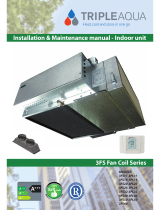
Fig. 1 Dimensions (mm)
Not to Scale
NOTE
The manufacturer reserves the right to change specications at any time
without notice or obligation. Certied dimensions available on request.
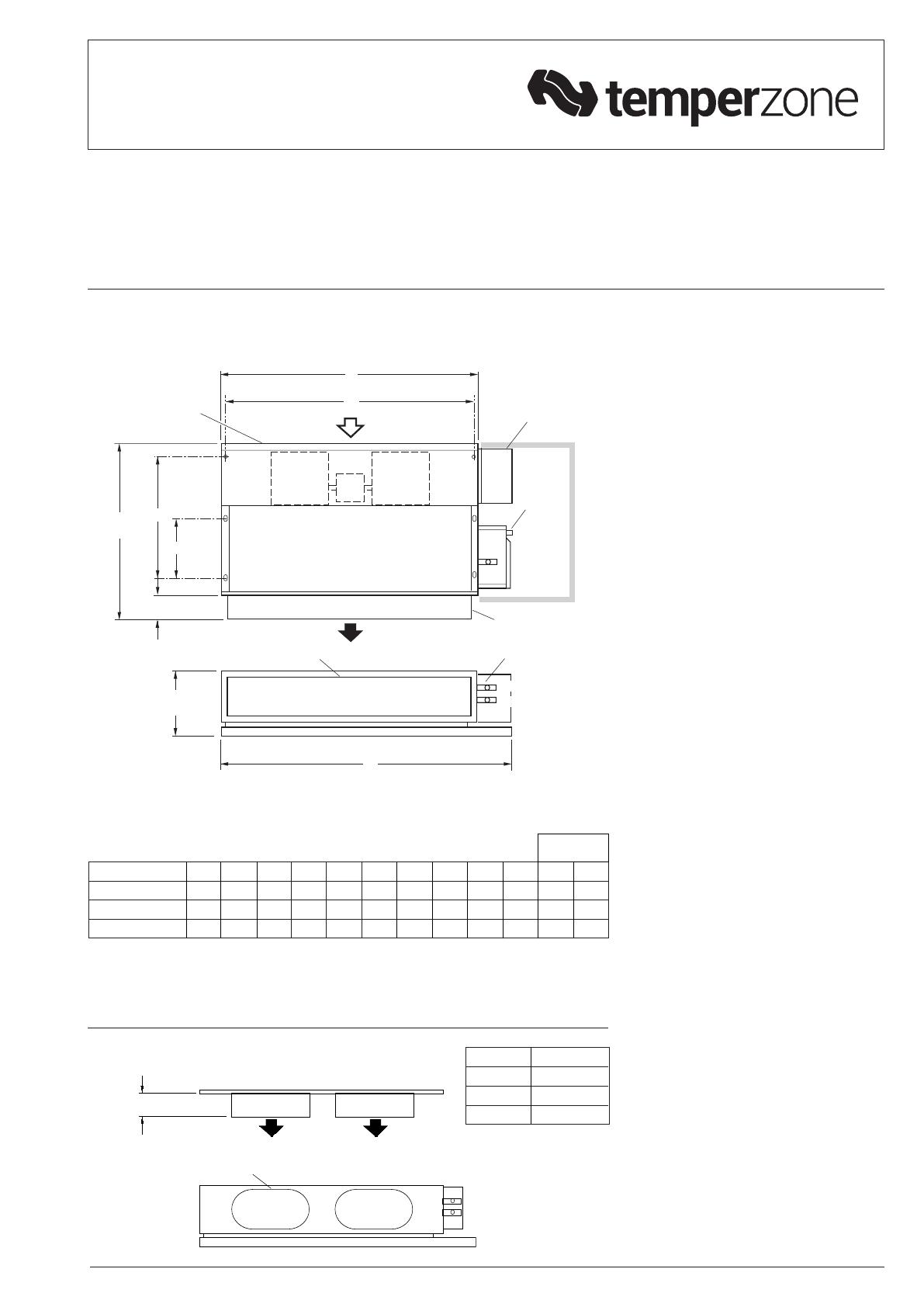
Fig. 2 Optional Supply Air Spigots
SPIGOTS TO SUIT
FLEXIBLE DUCTING
100
MODEL SPIGOTS
IMDL 40 200 dia (x2)
IMDL 60 250 dia (x2)
IMDL 90 250 dia (x3)
Right Handed model shown
MODEL A B C D E F G H J K COLD HOT
IMDL 40 680 715 250 550 245 512 170 525 225 470 20 13
IMDL 60 930 715 250 795 245 762 170 775 225 470 20 13
IMDL 90 1195 755 260 1050 255 1012 179 1025 265 510 25 13
A
OVERALL
C
OVERALL
D
(HEIGHT = E)
H
500 MIN. CLEARANCE
100
DRAIN
19 OD
ELECTRICAL
BOX
WATER
CONN'S
SUPPLY AIR
SPIGOT
F x G
S/A SPIGOT
K
FILTER ACCESS
EITHER END,
OR LIFT OUT
B
OVERALL
J
IN
OUT
A
OVERALL
C
OVERALL
D
(HEIGHT = E)
H
500 MIN. CLEARANCE
100
DRAIN
19 OD
ELECTRICAL
BOX
WATER
CONN'S
SUPPLY AIR
SPIGOT
F x G
S/A SPIGOT
K
FILTER ACCESS
EITHER END,
OR LIFT OUT
B
OVERALL
J
IN
OUT
WATER CONN'S
BSP MALE
Note:
1. Allow adequate clearance for the lter (if tted) to be removed.
2. Left handed models have drain exit nearer supply air side.
Hoses may need to be insulated to meet
local building regulations.
Poor quality water supply must be pre-
ltered and it is essential that adequate
water treatment is maintained, particularly
where open cooling towers are used.
Condensate Drain
The drain should have a slope of at least
1 in 50 and must not be piped to a level
above the unit drain tray. Fit a vent pipe
within 500 mm of the unit (see Fig.3).
Check the drain by pouring water into the
drain tray and ensuring that it clears.
ELECTRICAL WIRING
The electrical supply required is:
1 phase 220-240 V a.c. 50 Hz with neutral
and earth. The supply to have an isolation
switch adjacent to the unit but not attached
to the unit. Recommended external circuit
breaker size is 5 amp.
Electrical work must be carried out by a
qualied electrician in accordance with local
supply authority regulations and the wiring
diagram.
INDOOR FAN SPEED
The fan speed can be set to LOW, MED, or
HIGH - whichever best suits the application.
ELECTRIC HEAT (Option)
Units installed with electric heat elements
include both auto (90°C) and manual
(120°C) high temp. safety thermostats. If
the manual high temp. safety t/stat requires
resetting and the auto high temp. safety
t/stat does not reset, then the latter needs to
be replaced.
COMMISSIONING
1. Check that the thermostat is
correctly wired and set at the desired
temperature.
2. Check that the air lter is clean.
3. Check that the fan runs freely without
vibration.
4. Check condensate drain for free
drainage.
MAINTENANCE
Weekly For First Four Weeks
1. Check air lter; vacuum clean as
necessary.
2. Check condensate drain for free
drainage.
Monthly
Check air lter; vacuum clean as necessary.
Six Monthly
1. Check condensate drain for free
drainage.
2. Check heat exchanger coil; vacuum or
brush clean as necessary.
3. Check the tightness of the fan.
4. Check that fan motor is free running.
5. Check tightness of electrical connections.
6. Check air supply at diffuser outlets.
NOTE
The manufacturer reserves the right to
change specications at any time without
notice or obligation. Certied dimensions
available on request.
SIDE VIEW
Fig. 3 Condensate Drain
This pamphlet replaces the previous
issue no. 3180 dated 02/22.
Wiring rev. F for EH
500
MAX.
10 ID
VENT PIPE
19 ID DRAIN
300
ADJUSTABLE
SUPPORT BRACKET
Standard Unit
Drawn:
Apprvd:
Title: Drawing No: Rev:
Date:
©temperzone Ltd 2015
Visit http://www.temperzone.biz for client wiring schematics
DO NOT
SCALE - ASK
Client Wiring
01 2 3 4 5 6 7 8 9
A
B
C
D
E
F
G
SHEET OF 1
1
D
291-000-894
Electrical Wiring Schematic
IMDL 40/60/90
M.A.H. 19/06/2015
L1
N
REV MODIFICATION DATE ECN APVD
CUpdated all earth symbols 29-03-16 N3829 M.A.H.
*D Corrected TB designation - TB3 was TB2 11-10-18 N4152 L.O.L.
Client Protection & Isolation Switch
TB3
L
M
H
ORG
BRN (HIGH)
WHT (LOW)
RED (MED) BLU
ORG
IFM1
OPTIONAL
On/Off and
3 speed
switch LOW
MED
HIGH
On/Off
Model / Version IMDL40 IMDL60 IMDL90
0.40A 0.60A 0.60A
0.45A 0.60A 0.70A
Fan motor
full current
load (FLA)
S
M
H0.60A 0.70A 1.40A
Remove loop when
optional 3 speed
switch is used (3-D)
CAP Capacitor
IFM1 Indoor Fan Motor
D
ETH2
ETH1
08/22 Pamphlet No. 3180 © temperzone limited 2022
Drawn:
Apprvd:
Title: Drawing No: Rev:
Date:
©temperzone Ltd 2015
Visit http://www.temperzone.biz for client wiring schematics
DO NOT
SCALE - ASK
Client Wiring
01 2 3 4 5 6 7 8 9
A
B
C
D
E
F
G
SHEET OF 1
1
F
291-000-895
Electrical Wiring Schematic
IMDL 40/60/90 c/w Electric Heat
M.A.H. 18/06/2015
L1
N
REV MODIFICATION DATE ECN APVD
FUpdated Fan Run On Timer wiring. 26-07-22 5043 P.P.D.
EPF: Rename terminal blocks - TB6,7,8 was TB2,3,4; Added client wiring note 17-03-17 N3897 L.O.L.
Client Protection & Isolation Switch
TB6
F
1
2
TB7
L
M
H
TB8
COOL
HEAT
ORG
BRN (HIGH)
WHT (LOW)
RED (MED) BLU
ORG
IFM1
MST
HST
OPTIONAL
3 speed
switch LOW
MED
HIGH
Thermostat
T/Stat - must be a
"HEAT/COOL" type, NOT
reverse cycle heat pump
IMPORTANT:
24 hour power supply is essential
Remove loop when
optional 3 speed
switch is used (3-D)
Electric heat kW 1.5 2.0 3.0
Model / Version IMDL40 IMDL60 IMDL90
0.40A 0.60A 0.60A
0.45A 0.60A 0.70A
Fan motor
full load
current
(FLA)
S
M
H0.60A 0.70A 1.40A
L1
N
CAP Capacitor
EHC1 Electric Heating Contactor
EHC2 Silent Operation Relay
ETH Earth
FROT Timer Fan Run On 240V 10A
HE Heater Element
HST Auto High Temp. T/Stat
IFM1 Indoor Fan Motor
MST Manual High Temp. T/Stat
TB Terminal Block
A1 B1 A2
15 16 18
Set top "Mode" selector switch to "sf"
Set middle "T" to "1m"
Set bottom "t" selector to "1"
Fan Run-on Timer settings:
F
FROT
FF
ETH1 Gearplate
ETH2 Lid
ETH1
ETH2
ETH1
Standard Unit c/w Electric Heat
  • Page 1 1
  • Page 2 2
  • Page 3 3
  • Page 4 4

temperzone IMDL 40 User manual

Type
User manual

The temperzone IMDL 40 is a ducted fan coil unit designed for efficient cooling and heating in residential and commercial spaces. With its compact size and flexible installation options, it offers a range of features to enhance indoor comfort and air quality. The unit's adjustable fan speed allows for customized airflow, while the built-in condensate drain ensures efficient removal of excess moisture. Backed by regular maintenance, the IMDL 40 promises long-lasting performance and energy efficiency.

Ask a question and I''ll find the answer in the document

Finding information in a document is now easier with AI