Page is loading ...

Duct EZY 8/11 Kit
for Ducted
Split Systems Installation
Instructions
905 x 455 mm to provide a xing
surface for the grille.
3. Insert the frame of the return grille
into its hole. Afx the frame by drilling
through the side of the grille frame,
close to the top, into the supporting
wooden framework. Screw in at least
four places to ensure it is fully secure.
4. Discard the blanking insulation panel for
dual duct applications.
5. Position indoor unit within the ceiling
cavity approximately in the middle
between the supply and return grilles.
Indoor Unit Mounting
Firstly, read the instructions that are
supplied with the indoor unit.
The indoor unit can be mounted either hung
from the ceiling structure or sat on a level
platform over ceiling joists.
If mounting the indoor unit by hanging:
Add the hanger brackets (supplied) to
the indoor unit as per instruction sheet.
Securely hang via hanger rods (Note:
hanger rods/nuts/washers need to be
provided by the installer. Also note,
some extra framing within the roof
trusses may be required to hold the top
of the hanger rods).
If sitting the indoor unit on ceiling joists:
Securely position across multiple joists,
ensuring that satisfactory rubber mounts
are placed between the unit and the
joists to remove any possibility of noise
passing to the occupied space below.
6. Attach the supply and return plenums
to the indoor unit with screws (provided
by installer). Seal the outside of the joint
between the plenum and unit with duct
tape (supplied).
7. Attach the supply duct to the supply
plenum. Push the duct fully on to the
plenums supply spigots and tape on
with duct tape.
Supply Air Diffusers
8. Mark the position of the supply diffuser
and cut out the appropriate holes using
the templates provided with the supply
air diffusers.
9. Stretch out exible supply duct and put
through cut holes. Ensure duct is fully
stretched out and bends are as gentle
as possible. Tape duct to supply diffuser
inlets.
Note: Tight bends or compressed
duct will restrict air ow and reduce
performance.
10. Push supply diffusers in to cut holes
ensure the latches snap in to place.
Return Air Grille
11. Fix return air plenum to indoor unit with
screws (provided by installer). Seal the
joint between the plenum and unit with
duct tape.
Optional
Duct EZY 11 Expansion Kit – enables a
greater distance between the Hitachi indoor
unit and supply air diffuser. Includes:
1. Flexible duct for supply air (250 dia x 3m)
2. Duct joiner (250 dia.).
3. Manually adjustable regulating damper
(250 dia.).
Duct EZY 8 suitable expansion components
are available separately from Temperzone.
INSTALLATION
Plan
Before starting, decide approximate position
for supply and return air grilles. Refer pages
2 and 3 for typical home and ofce layouts.
Note: The maximum span between the
return grille and any supply grille is around
6 m - as all ducts are 3 m long. Positioning
should take account of any obstacles in the
ceiling space. The return air grille/s should
be placed where the lter can be easily
accessed, eg in a hall-way.
For existing buildings with xed ceilings,
there must be a way of getting the indoor
unit into the ceiling space.
Note: The Duct EZY 11 indoor unit will t
through the supplied return air grille.
This kit is designed to suit a typical home/
ofce layout. Any alterations/extensions
to the supplied equipment may result in
reduced system performance. If in doubt,
refer to Temperzone.
Return Air Grille
1. Duct EZY 8 (SKH-DEZ-082):
Cut a 405 x 405 mm hole in ceiling to t
400 x 400 return air grille,
Duct EZY 8 (SKH-DEZ-L82):
Cut a 910 x 460 mm hole in ceiling to t
900 x 450 return air grille.
Duct EZY 11 Single:
Cut a 910 x 460 mm hole in ceiling to t
900 x 450 return air grille.
Duct EZY 11 Dual:
Cut two 405 x 405 mm holes in ceiling to
t 400 x 400 return air grilles.
2. Duct EZY 8 or Duct EZY 11 Dual:
Frame out the hole as necessary
for the return grille/s to no smaller than
405 x 405 mm (or 910 x 460 mm if
applicable) to provide a xing surface for
the grille.
Duct EZY 11 Single:
a. Pass the indoor unit through this hole
by orientating correctly. If necessary
the supply and return anges can be
unscrewed from the indoor unit to
increase clearance. In extreme cases
the fan and coil sections of the indoor
unit can be separated to further aid
access.
b. Frame out the hole as necessary
for the return grille to no smaller than
GENERAL
Duct EZY is a ready designed, premium
ducted air conditioning package.
This installation instruction is to be read in
conjunction with the separate installation
instructions supplied with the Hitachi indoor
and outdoor units.
This kit must be installed in accordance with
all national and local safety codes.
Duct EZY 8 Kit Components
(SKH-DEZ-082 or SKH-DEZ-L82)
1. Hitachi RAD-E70 Ducted indoor unit.
2. Hitachi RAC-E70 Inverter outdoor unit.
3. Hitachi Wall controller (SPX-WKT3).
4. Supply Air Diffuser (RPD-200: 200 dia.)
(x3).
5. Flexible duct for supply air (200 dia x 3m)
(x3).
6. Supply air plenum, 200 dia. outlets (x3).
7. Return air plenum, single inlet, 350 dia.
8. Flexible duct for return air (350 dia. x 3m)
(x1).
9. Return air grille with hinged lter & adaptor
(400 x 400mm or 900 x 450mm).
10. Duct tape roll 30m.
Check that all parts listed are supplied.
Duct EZY 11 Kit Components
1. Hitachi RPI Ducted indoor unit.
2. Hitachi RAS Inverter outdoor unit.
3. Hitachi Wall controller (PC-ARF).
4. Hanger bracket set for indoor unit
(4 brackets).
5. Supply Air Diffuser (RPD-250: 250 dia.)
(x4).
6. Flexible duct for supply air (250 dia x 3m)
(x4).
7. Supply air plenum, 250 dia. outlets (x4).
8. Return air plenum, 2 inlets, 350 dia. ea.
9. Flexible duct for return air (350 dia. x 3m)
(x2).
10. Single Return Version (SKH-DEZ-111):
Return air grille with hinged lter &
adaptor (900 x 450 mm).
Dual Return Version (SKH-DEZ-D11):
Return air grille with hinged lter &
adaptor (600 x 600 mm) (x2).
11. Duct tape roll 30m.
Check that all parts listed are supplied.
Required but not included:
1. Timber for box framing and mounting
Return Air grille/s.
2. Screws to secure plenums to indoor
unit.
3. Timber framing between joists to enable
optional suspension of indoor unit.
4. Hanger rods/nuts/washers for optional
suspending of indoor unit.
5. A platform and anti-vibration mounts or
pads if planning to site the indoor unit on
top of/across ceiling joists.

18. Using normal install practices, run the
pipe work between the indoor and
outdoor units. Flare and connect as
normal.
Outdoor Unit
(To be read in conjunction with the
instructions that are supplied with the
outdoor unit.)
19. Install outdoor unit on suitable feet /
pad, and connect all wiring & piping as
necessary following good refrigeration
installation practices.
20. Complete refrigeration requirements
by pressure testing, vacuuming, and
charging refrigerant piping as required.
Double check for any leaks.
21. Power up system but do not start.
Leave to sit for up to 4 hours to allow
compressor crankcase to come up to
temperature.
22. Start unit and ensure it is running
correctly in both heating and cooling
modes. Balance airow as required by
opening / closing supply are grilles.
23. Explain operation of wall controller
to end user and leave the operation
manual for them.
12. Attach the 350 dia. return air exible
duct to the return plenum. Push the duct
fully on to the plenums spigots and tape
on with duct tape.
13. Stretch out exible supply duct. Tape
duct to return grille spigots. Ensure duct
is fully stretched out and bends are as
gentle as possible.
Note: Tight bends or compressed
duct will restrict air ow and reduce
performance.
14. Attach face of grille, partially close,
insert lters then fully close and latch by
turning fasteners provided.
Indoor Unit
(To be read in conjunction with the instruc-
tions that are supplied with the indoor unit.)
15. Using normal installation practices, run
a drain pipe (25 mm) from the indoor
unit to a suitable drain point, ensuring
the drain pipe has a constant fall on it.
16. Using normal install practices, attach
an interconnecting wire to the terminal
block of the indoor unit as per the wiring
instructions supplied with the indoor
unit. Run this wire to the position of the
outdoor unit.
17. Using normal install practices, attach a
remote control wire (screened) to the
terminal block of the indoor unit as per
the wiring instructions supplied with the
indoor unit. Run this wire to the position
of the wall controller.
MAINTENANCE
Six Monthly
Replace or vacuum clean return air lter.
Refer to Hitachi units' instructions for
additional maintenance requirements.
Supply air diffusers: Wipe with a damp cloth
or vacuum any dust accumulation.
NOTE
The manufacturer reserves the right to
change specications at any time without
notice or obligation.

EN
S
UIT
E
BATHR
OOM
KIT
C
HE
N
W
ALK I
N
LIVIN
G
MA
S
TE
R
BEDR
OOM
6. 1. 3. 4.
9. 7.2. 5. & 8.
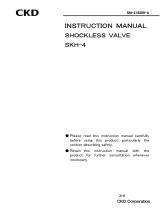
Typical Home Layout
KEY
1. Hitachi Ducted indoor unit.
2. Hitachi Inverter outdoor unit.
3. Hitachi Wall controller.
4. Supply Air Diffuser.
5. Flexible duct for supply air (3m).
6. Supply air plenum.
7. Return air plenum.
8. Flexible duct for return air (3m)
9. Return air grille (single or dual) with
hinged lter & boots.
Duct EZY 11
example
shown here

© temperzone limited 202211/22 Pamphlet No. 4119
RECEPTI
O
N
MEETIN
G
O
FFICE
PL
AN
O
FFIC
E
5. & 8. 1. 3. 4.
9. 7. 2. 6.
Typical Ofce Layout
KEY
1. Hitachi Ducted indoor unit.
2. Hitachi Inverter outdoor unit.
3. Hitachi Wall controller.
4. Supply Air Diffuser.
5. Flexible duct for supply air (3m).
6. Supply air plenum.
7. Return air plenum.
8. Flexible duct for return air (3m)
9. Return air grille (single or dual) with
hinged lter & boots.
Duct EZY 11
example
shown here
/