Page is loading ...

S C12 - 3 0
MULTI-CHANNEL AMPLIFIER
INSTALLATION GUIDE

www.SpeakerCraft.com
Thank you for purchasing the SpeakerCraft SC12-30, one of the most versatile
and powerful multi-channel ampliers ever offered. Like all SpeakerCraft
products, the SC12-30 is built to the highest standards of quality and reliability.
With proper installation and operation, you’ll enjoy years of trouble-free use.
TABLE OF CONTENTS
INTRODUCTION 4
FEATURES AND BENEFITS 5
SYSTEM DESIGN BASICS 7
SYSTEM DESIGN CONSIDERATIONS 9
APPLICATIONS 11
CONFIGURING YOUR SYSTEM 15
INSTALLATION CONSIDERATIONS 16
FRONT AND REAR PANEL DETAILS 18
INSTALLATION 20
OPERATION 25
TROUBLESHOOTING GUIDE 27
SPECIFICATIONS 29
CONFIGURATION WORKSHEET 30
CONGRATULATIONS!

3
12 Channel, BridgeaBle Power amPlifiers
SpeakerCraft – 1-800-472-5555 – 1-707-778-5733
ImpORTANT SAFETy INSTRUCTIONS
1. Read these instructions.
2. Keep these instructions.
3. Heed all warnings.
4. Follow all instructions.
5. Do not use this apparatus near water.
6. Clean only with a dry cloth.
7. Do not block any ventilation openings. Install in
accordance with the manufacturer’s instructions.
8. Do not install near any heat sources such as
radiators, heat registers, stoves or other apparatus
(including ampliers) that produce heat.
9. Do not defeat the safety purpose of the polarized
or grounding-type plug. A polarized plug has two
blades with one wider than the other. A grounding-
type plug has two blades and a third grounding
prong. The wide blade or the third prong is provided
for your safety. If the provided plug does not t into
your outlet, consult an electrician for replacement of
the obsolete outlet.
10. Protect the power cord from being walked on
or pinched, particularly at plugs, convenience
receptacles and the point where they exit from the
apparatus.
11. Only use attachments/accessories specied by
the manufacturer.
12. Use only with the cart, stand,
tripod, bracket or table specied by the
manufacturer or sold with the apparatus.
When a cart is used, use caution when
moving the cart/apparatus combination
to avoid injury from tip-over.
13. Unplug this apparatus during lightning storms or
when unused for long periods of time.
14. Refer all servicing to qualied service personnel.
Servicing is required when the apparatus has been
damaged in any way, such as power supply cord or
plug is damaged, liquid has been spilled or objects
have fallen into the apparatus, the apparatus has
been exposed to rain or moisture, does not operate
normally, or has been dropped.
15. Do not expose this apparatus to dripping or
splashing and ensure that no objects lled with
liquids, such as vases, are placed on the apparatus.
16. To completely disconnect this apparatus from
the AC Mains, disconnect the power supply cord
plug from the AC receptacle.
17. The power supply cord (sometimes referred
to as the “Mains Plug”) is used as the disconnect
device and shall remain accessible and operable at
all times.
18. Do not expose batteries to excessive heat such
as sunshine, re or the like.
19. Open ame sources, such as lighted candles,
should NOT be placed on the apparatus.
WARNING: To reduce the risk of fire or electric
shock, do not expose this apparatus to rain or
moisture.
The lightning ash with arrowhead
symbol, within an equilateral triangle, is
intended to alert the user to the
presence of uninsulated “dangerous
voltage” within the product’s enclosure
that may be of sufcient magnitude to constitute a
risk of electric shock to persons.
The exclamation point within an
equilateral triangle is intended to alert
the user to the presence of important
operating and maintenance (servicing)
instructions in the literature accompanying the
product.
FCC Required Text:
NOTE: This equipment has been tested and found
to comply with the limits for a Class B digital
device, pursuant to part 15 of the FCC Rules.
These limits are designed to provide reasonable
protection against harmful interference in a
residential installation. This equipment generates,
uses, and can radiate, radio frequency energy
and, if not installed and used in accordance with
the instructions, may cause harmful interference
to radio communications. However, there is no
guarantee that interference will not occur in a
particular installation. If this equipment does cause
harmful interference to radio or television reception,
which can be determined by turning the equipment
off and on, the user is encouraged to try to correct
the interference by one or more of the following
measures:
—Reorient or relocate the receiving antenna.
—Increase the separation between the equipment
and receiver.
—Connect the equipment into an outlet on a
circuit different from that to which the receiver is
connected.
—Consult the dealer or an experienced radio/TV
technician for help.
Changes or modications not expressly approved
by the party responsible for compliance could void
the user’s authority to operate the equipment.

4
www.SpeakerCraft.com
INTROdUCTION
BRIdGABLE pOwER AmpLIFIERS
More power, more channels and more music. SpeakerCraft ampliers deliver
the power and delity you demand whether you need a couple of channels
for stereo or you want to distribute music throughout your home.
When SpeakerCraft set out to develop the custom installation industry’s most
complete line of ampliers, we knew we had to have answers for the variety
of situations that you encounter.

5
12 Channel, BridgeaBle Power amPlifiers
SpeakerCraft – 1-800-472-5555 – 1-707-778-5733
FEATURES ANd BENEFITS
REAL wORLd pOwER
The SC12-30 is a 12-channel amplier that delivers a solid 30 watts per channel
RMS into 8 ohms and 40 watts per channel RMS into 4 ohms. A new digital
power transformer design provides the energy necessary to efciently deliver
solid, deep, controlled bass response to a house full of speakers.
TwELvE TO SIx ChANNEL CONFIGURABLE pOwER
Each of the SC12-30’s six adjacent speaker output pairs are bridgeable.
You can create up to six 80 watt channels by sliding the bridging switches
located between each pair to the “bridged” position. This enables you to
allocate more power to specic locations, such as large rooms or outdoor
applications.
FREEdOm FROm NOISE ANd CROSS-TALk
The SC12-30’s BusMatrix™ incorporates advanced PCB construction ensuring
extremely high channel to channel isolation. Signal to noise ratios and cross-talk
are equivalent to a professional mixing board found in a recording studio. With
the SC12-30, the music playing in the living room cannot interfere with
the music in the den.
TRANSpARENT SOUNd
The audio circuitry of the SC12-30 is constructed with the nest parts available,
including 1% metal lm resistors, high quality capacitors and oversized heat
sinks. All this attention to technical detail results in a sound that is clear and
uncolored.
BUSmATRIx™ SELECTOR
Our unique BusMatrix™ selector gives you the exibility to assign each channel
to a common Left, Right, or Mono signal bus, or to a dedicated signal input.
With BusMatrix™, routing surround sound to the master bedroom, stereo
to the den and mono to the powder room is as simple as icking a switch.
BusMatrix™ makes the SC12-30 an ideal multi-room or multi-zone amplier and
offers exciting new features and system design possibilities to the professional
installer.

6
www.SpeakerCraft.com
FEATURES ANd BENEFITS CONTINUEd...
INdEpENdENT LEvEL CONTROLS
Each amplier channel has an independent level control enabling you to adjust
the volume settings for twelve different speaker locations individually. Each
speaker can now be adjusted specically for its location and for who will be
listening!
TURN-ON mOdES
The SC12-30 features three turn-on modes:
1. Manual turn-on via the front panel switch and
2. Audio Sense and
3. External Voltage trigger. Audio Sense and External Voltage trigger modes
enable you to congure the SC12-30 to interface with any kind of system
and turn on automatically.
AUTOmATIC pROTECTION
Each channel has independent thermal and short circuit protection. In the
unlikely event that a problem occurs on one channel, the other channels will
continue to play. When conditions return to normal, regular operation resumes.
STATUS dISpLAy FOR TROUBLEShOOTING
LED’s on the front panel indicate Power, Active and Protection Status. With
a glance at the frontpanel a troubleshooter is quickly provided with key
information!
dESIGNEd ANd ENGINEEREd IN ThE USA
Limited two-year parts and labor warranty.

7
12 Channel, BridgeaBle Power amPlifiers
SpeakerCraft – 1-800-472-5555 – 1-707-778-5733
SySTEm dESIGN BASICS
As shown in Figure 1, a distributed audio/video system is dened by the number
of listening zones it has. Within a listening zone you can listen to only one
source (e.g. CD, Radio, iPod, etc.) at any one time. A listening zone can consist
of a single room or a group of rooms. To achieve different volumes and greater
convenience in different rooms within a zone, individual volume controls can be
used. SpeakerCraft makes volume controls in various styles and colors. When
designing your system, take into account who will use the system and when
they will use it. Consult your local SpeakerCraft dealer for more information.
RECEIVER
Family Room Living Room
Figure 1
Cable
Box
CD
Player
Blu-ray
Player
LCD
Listening Zone 1

8
www.SpeakerCraft.com
SySTEm dESIGN BASICS CONTINUEd...
A MultiZone system as shown in Figure 2, offers the household more exibility.
For instance, a family might have their family room wired for surround sound
and their living room wired for background music. In a two zone system, the
children can watch TV in surround sound while Mom and Dad are reading the
paper and enjoying background music in the living room.
Figure 2
Cable
Box
CD
Player
Blu-ray
Player
LCD
Family Room
Living Room
RECEIVER RECEIVER
Listening Zone 1 Listening Zone 2

9
12 Channel, BridgeaBle Power amPlifiers
SpeakerCraft – 1-800-472-5555 – 1-707-778-5733
SySTEm dESIGN CONSIdERATIONS
SpEAkER COmpATIBILITy
A single channel (not bridged) of the SC12-30 is capable of driving a 4 ohm
impedance speaker load. No more than two 8 ohm speakers or no more than
one 4-6 ohm speaker can be safely connected to a single channel. Proper
ventilation of the SC12-30 is critical when driving lower impedance loads. If the
SC12-30 is not properly ventilated, the protection circuits may activate and shut
off the channel at higher volume levels (for more information on proper amplier
placement, see Installation Considerations on page 16).
A channel pair that has been BRIDGED is capable of driving an impedance
load of 8 ohms. Proper ventilation of the SC12-30 is critical when driving a
8 ohm load with bridged channels. If the SC12-30 is not properly ventilated,
the protection circuits may activate and shut off the channel at higher volume
levels (for more information on proper amplier placement, see Installation
Considerations on page 16).
When designing your system, try to specify 6-8 ohm speakers (SpeakerCraft
offers a complete line of inwall, in-ceiling, outdoor and home theater
loudspeakers with all models rated from 6-8 ohms).
CABLE ANd wIRE
Because the SC12-30 has many connections on the rear panel (see Figure
12), it is important that you correctly label all of the input cables and speaker
wires. Label the cables and wires with their destination or source, rather than
the SC12-30 terminal to which they are connected. This will make it easier to
recongure your system in the future.
The SC12-30 connects to your sources via shielded line level audio cables with
RCA connectors. Use high quality cables with your SpeakerCraft amplier for
the lowest possible noise and best overall performance. Your SpeakerCraft
dealer can recommend the proper cable.
The SC12-30 connects to your speakers using two conductor speaker wire.
For most applications, we recommend you use 16 or 18 gauge wire. For
wiring runs longer than 80 feet, we recommend 14 gauge wire. The SC12-30’s
high-quality, gold-plated 5-way binding posts will accommodate up to 12-gauge
wire. Attaching banana plugs to the wire will enable the connection of larger
wire sizes.

10
www.SpeakerCraft.com
SySTEm dESIGN CONSIdERATIONS CONTINUEd...
USING mONO FOR SmOOThER COvERAGE
In large or irregularly shaped rooms, you may nd that the main listening
area may be closer to one of the speakers. If the speakers in the room are
connected to a stereo amplier you will only hear half the music. The SC12-
30’s BusMatrix™ enables you to create mono sound from one speaker without
impacting the stereo quality in the rest of the system. You can congure each
room to either stereo or mono as needed with no ill effects. Some of the most
popular areas where mono will greatly enhance the sound quality would be:
• Large rooms with many seating areas and/or many pairs of speakers.
• Irregularly shaped rooms.
• Bathrooms with one speaker over the tub and one speaker over the sink(s).
• Hallways or passageways (including those with multiple speakers).
• Small rooms, such as walk-in closets where more than a single speaker is not
required.
BRIdGING ChANNELS FOR AREAS
ThAT REqUIRE mORE vOLUmE ANd pOwER
There are several situations where bridging is an excellent way to improve the
sound. There are also applications where bridging would seem to be appropriate
but is not recommended. Bridging channels increases the power output to
80 watts per channel at 8 ohms.
These are some of the most common DOs and DON’Ts:
1. Outdoors (DO) — Sound dissipates faster outside than it does in a room
where the walls enclose the sound and reect it back to the listener. A pair of
speakers playing into a large patio or yard will greatly benet from bridging
four channels into two 80 watt channels.
2. Surround Sound Systems (DO) — The dynamic demands for the center
channel are much greater than the left, right or surround channels. This is an
excellent application for two channels to be bridged into one 80 watt channel.
3. More than one pair of 8 ohm speakers (DON’T) — In a large room or a
long hallway, often the best way to get good background music is to install
multiple pairs of speakers. You will actually deliver more power to two pairs of
8 ohm speakers by using two unbridged amplier channels than you would if
you bridged four amplier channels into two and connected the two pairs of
speakers in parallel.

11
12 Channel, BridgeaBle Power amPlifiers
SpeakerCraft – 1-800-472-5555 – 1-707-778-5733
AppLICATIONS
AdvANTAGES OF USING ThE SC12-30 IN A
SINGLE ZONE SySTEm
When you connect the preamplier outputs of your stereo receiver or stereo
preamplier to the SC12-30 BusMatrix™ you dedicate a robust 30 watts to each
speaker in your multi-room system as shown in Figure 3.
Each channel of the SC12-30 has its own level control so you can compensate
for architectural differences that create sonic imbalances. In addition, you can
ne tune the system so that when all of the room volume controls are set to the
loudest level, the large rooms and the small rooms play at the same volume.
PRE-AMP or
AM/FM RECEIVER
SC12-30
Figure 3
Cable
Box
CD
Player
Blu-ray
Player
Single Zone

12
www.SpeakerCraft.com
AppLICATIONS
USING A dUAL-ZONE RECEIvER FOR TwO LISTENING ZONES
Most of today’s Dolby Digital Audio Video Receivers include a second zone
preamplier output to create a second listening zone. Using this output with the
SC12-30 BusMatrix™ input provides amplication for multiple rooms within a
second listening zone as shown in Figure 4.
In addition, in this example high power is supplied to the patio stereo speakers by
bridging channel pair 9 and 10 for the left speaker and bridging channel pair
11 and 12 for the right speaker.
DUAL-ZONE SURROUND
SOUND RECEIVER
Front Speakers Center Speakers
Living Room Kitchen Ofce Bedroom Patio
(Bridged Channels
9-10, 11-12)
Rear Speakers
BusMatrix™
SpeakerCraft High Power
Volume Controls
SI-1230
Figure 4
Cable
Box
CD
Player
Blu-ray
Player
Zone 2
Zone 1
(Home Theater)

13
12 Channel, BridgeaBle Power amPlifiers
SpeakerCraft – 1-800-472-5555 – 1-707-778-5733
AppLICATIONS
ExpANdING A mULTI-ZONE SySTEm
TO INCLUdE mORE ROOmS
In the ultimate Multi-Zone system, you connect six stereo preampliers (or a
single component multi-zone/multi-source preamplier) to the dedicated inputs
of SC12-30. These dedicated input signals are then routed to the appropriate
amplier channels via dip switch settings creating completely independent
listening zones.
Multi-Zone systems enable listeners located in the separate zones to
simultaneously listen to different source components as shown in Figure 5.
Room 1 Room 2 Room 3 Room 4 Room 5
BusMatrix™
SpeakerCraft
High Power
Volume Controls
Zone 1 - 4
Speaker Outputs
Zone 5
Preamp Output
(set to xed)
SC12-30
SpeakerCraft MRA-664
Multi Room Audio Controller
Cable
Box
CD
Player
Blu-ray
Player
Zone 1 Zone 2 Zone 3 Zone 4
Figure 5

14
www.SpeakerCraft.com
AppLICATIONS
AddING pREAmpS TO CREATE mORE LISTENING ZONES
In the ultimate Multi-Zone system, you connect stereo preampliers (or a single
component multi-zone/multi-source preamplier) to the dedicated inputs of
SC12-30. These dedicated input signals are then routed to the appropriate
amplier channels via dip switch settings creating completely independent
listening zones.
Multi-Zone systems enable listeners located in the separate zones to
simultaneously listen to different source components as shown in Figure 6.
Matrix Switching
Preamp
SC12-30
Dedicated Inputs
Zone Outputs
Figure 6
Cable
Box
CD
Player
Blu-ray
Player
Zone 1 Zone 2 Zone 3 Zone 4 Zone 5 Zone 6

15
12 Channel, BridgeaBle Power amPlifiers
SpeakerCraft – 1-800-472-5555 – 1-707-778-5733
CONFIGURING yOUR SySTEm
Because the SC12-30 offers so many conguration possibilities it is important to
plan carefully before you install it. Draw a block diagram of your system and use
the Conguration Worksheet on page 27 to record how you plan to connect your
SC12-30.
Here is an example filled out according to the block diagram on page 10.
BUS INS & OUTS CONNECTED TO
CH# BRIDGED DIP INPUT SOURCE SPEAKER
MODE SETTINGS IN USE SPECIAL
Left Main Bus
Right Main Bus
Cascade Output
Constant
Audio Sense
Voltage Trigger
Control Output
1
2
3
4
5
6
7
8
9
10
11
12
Stereo Receiver - 2nd Zone - Left Pre-Output
Stereo Receiver - 2nd Zone - Right Pre-Output
L Main Bus Zone1 - Left
R Main Bus Zone1 - Right
L Main Bus Zone2 - Left
R Main Bus Zone2 - Right
L Main Bus Zone3 - Left
R Main Bus Zone3- Right
L Main Bus Zone4 - Left
R Main Bus Zone4 - Right
L Main Bus Zone5 - Left
R Main Bus Zone5 - Right
Example 1

16
www.SpeakerCraft.com
TURN ON MODE
AUDIO SENSE
CONSTANT
3-30V
AC/DC
TRIGGER
INPUT
INSTALLATION CONSIdERATIONS
Automating the turn-on of your SC12-30 is one of the easiest steps when installing
it in a distributed system. However, do not plug the main power cord into the
switched AC outlet of your preamplier or receiver. The high power design of the
SC12-30 requires large amounts of current from its AC power source. Additionally, it
is always recommended to activate the system preamplier/receiver before turning
on your SC12-30 in order to prevent system “turn-on thumps”. In order to address
these important needs, the SC12-30 has three special turn-on modes that let you
turn the amplier on only when it is needed. These three options are accessed by
the Turn-On Mode selector switch (see Figure 7).
Turn-On Modes
Constant – The auto turn-on circuitry is off. The
front panel master power switch operates the
amplier. In is “On”, Out is “Off”.
Audio Sense – The master switch on the
front panel must be in the “On” position. The
amplier is off when there is no audio signal
present at any of the audio inputs, but the
sensing circuitry is on. The turn-on sensing
circuitry looks for a signal present at any of the
audio inputs. If it detects a signal, the adjacent
pair of amplier channels (i.e. channel 1 & 2 , 3
& 4, etc.) assigned to receive the input signals
will turn on. Once the audio signal stops, the
sensing circuit waits two minutes, then turns all
amplier channels off.
3-24 Volt Ac/Dc Opto-Isolated Voltage Trigger - The Power switch on the front
panel must be in the “On” position for the voltage trigger to function. When a Trigger
Plug is inserted into the rear panel connector and the sensing circuitry detects a
voltage, the amplier is turned on. Once the Trigger voltage is turned off, the sensing
circuit instantly turns the amplier off. The amplier is off when there is no 3-24V
AC or DC voltage detected at the trigger input. Voltage triggers can be supplied
by SpeakerCraft automated switchers, some video projectors, some surround
sound processors, or something as simple as a 12 volt AC wall adapter plugged
into the switched outlet of your stereo receiver. Linear DC wall adapters are not
recommended; the long discharge time of the DC adapter’s lter capacitor will delay
the turn-off of the amplier. Trigger sources must be 3-24VAC or DC, 20mA or greater.
Figure 7
IMPORTANT! THE FRONT PANEL
POWER SWITCH MUST BE IN
THE ON (SWITCH IN) POSITION
FOR ANY OF THE THREE TURN-
ON OPTIONS TO FUNCTION

17
12 Channel, BridgeaBle Power amPlifiers
SpeakerCraft – 1-800-472-5555 – 1-707-778-5733
INSTALLATION CONSIdERATIONS
pLACEmENT
Place the SC12-30 on a at, level surface like a table or shelf. It should be placed
upright so that its weight rests on the unit’s four feet. PLACING THE WEIGHT OF
THE AMPLIFIER ON THE REAR OR FRONT PANEL FOR EVEN AN INSTANT WILL
RESULT IN DAMAGE TO THE AMPLIFIER’S CONNECTORS AND CONTROLS.
The SC12-30, like any hi- component, will last much longer if it is given
adequate ventilation for proper cooling. When installing the SC12-30 in a cabinet,
be sure that the rear of the cabinet is open to fresh air to provide proper cooling
(see Figure 10). If the cabinet’s design will not accommodate an open rear, install
two small “boxer fans” to provide continuous air ow into and out of the cabinet
(see Figure 11). Place the SC12-30 so that there is at least 5” of free air space
above the chassis. If the amplier is located on a carpeted surface, place a
board under the amplier’s feet. Do not block the ventilation holes on the top and
bottom of the SC12-30.
The SC12-30 is equipped with a digital power transformer. This transformer
generates a powerful magnetic eld which could induce hum in a turntable
(particularly a turntable equipped with a moving coil cartridge). Do not place a
turntable directly above or directly adjacent to the SC12-30.
Allow a minimum of 2” of depth behind unit
to accommodate cables and connectors.
If the cabinet rear is not open to fresh air or if you’re
using low impedance loads, install two “boxer fans”
to provide continuous air ow into and out of the
cabinet.
Boxer Fan (55 CFM)
directly centered 2”
behind the Amplier.
Boxer Fan (55 CFM)
directly centered 5” on
top of the Amplier.
Make sure that there is a minimum of 5” of free air
space above the amplier for proper ventilation.
Because the surface of the amplier may get hot, it
is recommended that a bafe or screen be placed
above the amplier to block hand access to the
top surface of the SC12-30.

18
www.SpeakerCraft.com
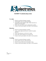
FRONT ANd REAR pANEL dETAILS
100-120 / 220-240 V~
50 / 60 Hz, 500W
TURN ON MODE
AUDIO SENSE
L
MAIN
BUS
INPUT
R
CONSTANT
3-30V
AC/DC
TRIGGER
INPUT
L
CASCADE
BUS
OUTPUT
R
12V CONTROL OUT
1
LEVEL
BRIDGED - BRIDGED +
1 2
LEVEL
BUS
USE CH 2
WHEN
BRIDGED
BRIDGED
4 Ω MINIMUM
(8 Ω MINIMUM IN BRIDGED MODE)
CLASS II WIRING
2
BUS
L
R
L+R
1
L
R
L+R
2
+
-
3
LEVEL
BRIDGED - BRIDGED +
3 4
LEVEL
BUS
USE CH 4
WHEN
BRIDGED
BRIDGED
4 Ω MINIMUM
(8 Ω MINIMUM IN BRIDGED MODE)
CLASS II WIRING
4
BUS
L
R
L+R
3
L
R
L+R
4
+
-
3
LEVEL
BRIDGED - BRIDGED +
3 4
LEVEL
BUS
USE CH 4
WHEN
BRIDGED
BRIDGED
4 Ω MINIMUM
(8 Ω MINIMUM IN BRIDGED MODE)
CLASS II WIRING
4
BUS
L
R
L+R
3
L
R
L+R
4
+
-
5
LEVEL
BRIDGED - BRIDGED +
5 6
LEVEL
BUS
USE CH 6
WHEN
BRIDGED
BRIDGED
4 Ω MINIMUM
(8 Ω MINIMUM IN BRIDGED MODE)
CLASS II WIRING
6
BUS
L
R
L+R
5
L
R
L+R
6
+
-
7
LEVEL
BRIDGED - BRIDGED +
7 8
LEVEL
BUS
USE CH 8
WHEN
BRIDGED
BRIDGED
4 Ω MINIMUM
(8 Ω MINIMUM IN BRIDGED MODE)
CLASS II WIRING
8
BUS
L
R
L+R
7
L
R
L+R
8
+
-
9
LEVEL
BRIDGED - BRIDGED +
9 10
LEVEL
BUS
USE CH 10
WHEN
BRIDGED
BRIDGED
4 Ω MINIMUM
(8 Ω MINIMUM IN BRIDGED MODE)
CLASS II WIRING
10
BUS
L
R
L+R
9
L
R
L+R
10
+
-
11
LEVEL
BRIDGED - BRIDGED +
11 12
LEVEL
BUS
USE CH 12
WHEN
BRIDGED
BRIDGED
4 Ω MINIMUM
(8 Ω MINIMUM IN BRIDGED MODE)
CLASS II WIRING
12
BUS
L
R
L+R
11
L
R
L+R
12
+
-
CAUTION: REPLACE WITH SAME TYPE AND
RATING FUSE
100-120V : T10AL/250V
FUSE:
100-120V ~
220-240V ~
220-240V : T5AL/250V
This device complies with Part 15 of the FCC Rules. Operation is subject to the following two conditions:
(1) This device may not cause harmful interference, and (2) This device must accept any interference
received, including interference that may cause undesired operation.
This Class B digital apparatus complies with Canadian ICES-003.
Cet appareil numérique de la classe B est conforme à la norme
NMB-003 du Canada.
Serial No.
Z619
SC12-30
Multi-Channel
Amplifier
Main Bus Inputs enable you to route
a stereo line level source to the
BusMatrix™ of the SC12-30
Cascade outputs of the main bus input
enable you to daisy chain multiple
amplifiers
3.5 mm Jack for
12v DC Control Output
“Turn-On” Mode Switch
3.5 mm Jack for
12v DC Control Input
Front panel “Master Power” switch turns off the
entire amplifier, including the Turn-On circuitry

19
12 Channel, BridgeaBle Power amPlifiers
SpeakerCraft – 1-800-472-5555 – 1-707-778-5733
FRONT ANd REAR pANEL dETAILS
100-120 / 220-240 V~
50 / 60 Hz, 500W
TURN ON MODE
AUDIO SENSE
L
MAIN
BUS
INPUT
R
CONSTANT
3-30V
AC/DC
TRIGGER
INPUT
L
CASCADE
BUS
OUTPUT
R
12V CONTROL OUT
1
LEVEL
BRIDGED - BRIDGED +
1 2
LEVEL
BUS
USE CH 2
WHEN
BRIDGED
BRIDGED
4 Ω MINIMUM
(8 Ω MINIMUM IN BRIDGED MODE)
CLASS II WIRING
2
BUS
L
R
L+R
1
L
R
L+R
2
+
-
3
LEVEL
BRIDGED - BRIDGED +
3 4
LEVEL
BUS
USE CH 4
WHEN
BRIDGED
BRIDGED
4 Ω MINIMUM
(8 Ω MINIMUM IN BRIDGED MODE)
CLASS II WIRING
4
BUS
L
R
L+R
3
L
R
L+R
4
+
-
3
LEVEL
BRIDGED - BRIDGED +
3 4
LEVEL
BUS
USE CH 4
WHEN
BRIDGED
BRIDGED
4 Ω MINIMUM
(8 Ω MINIMUM IN BRIDGED MODE)
CLASS II WIRING
4
BUS
L
R
L+R
3
L
R
L+R
4
+
-
5
LEVEL
BRIDGED - BRIDGED +
5 6
LEVEL
BUS
USE CH 6
WHEN
BRIDGED
BRIDGED
4 Ω MINIMUM
(8 Ω MINIMUM IN BRIDGED MODE)
CLASS II WIRING
6
BUS
L
R
L+R
5
L
R
L+R
6
+
-
7
LEVEL
BRIDGED - BRIDGED +
7 8
LEVEL
BUS
USE CH 8
WHEN
BRIDGED
BRIDGED
4 Ω MINIMUM
(8 Ω MINIMUM IN BRIDGED MODE)
CLASS II WIRING
8
BUS
L
R
L+R
7
L
R
L+R
8
+
-
9
LEVEL
BRIDGED - BRIDGED +
9 10
LEVEL
BUS
USE CH 10
WHEN
BRIDGED
BRIDGED
4 Ω MINIMUM
(8 Ω MINIMUM IN BRIDGED MODE)
CLASS II WIRING
10
BUS
L
R
L+R
9
L
R
L+R
10
+
-
11
LEVEL
BRIDGED - BRIDGED +
11 12
LEVEL
BUS
USE CH 12
WHEN
BRIDGED
BRIDGED
4 Ω MINIMUM
(8 Ω MINIMUM IN BRIDGED MODE)
CLASS II WIRING
12
BUS
L
R
L+R
11
L
R
L+R
12
+
-
CAUTION: REPLACE WITH SAME TYPE AND
RATING FUSE
100-120V : T10AL/250V
FUSE:
100-120V ~
220-240V ~
220-240V : T5AL/250V
This device complies with Part 15 of the FCC Rules. Operation is subject to the following two conditions:
(1) This device may not cause harmful interference, and (2) This device must accept any interference
received, including interference that may cause undesired operation.
This Class B digital apparatus complies with Canadian ICES-003.
Cet appareil numérique de la classe B est conforme à la norme
NMB-003 du Canada.
Serial No.
Z619
SC12-30
Multi-Channel
Amplifier
Bridging switches, BusMatrix controls,
dedicated inputs and level controls for each
channel
Gold-plated RCA jacks
Serial Number
Dual banana spaced binding post for
speaker connections
Removable Two-prong
16 gauge 6’ AC power cord
Power LED illuminates to confirm the amplifier is
connected to a live AC power outlet and that the
master power switch is on
Bicolor Status LED illuminates
“green” when the amplifier
circuitry has been turned on
by the Turn-On circuits, and
illuminates “red” to indicate
activation of the amplifier’s
built-in protection circuitry

20
www.SpeakerCraft.com
INSTALLATION
LINE LEvEL AUdIO INpUT
CAUTION! The amplifier must be off whenever you make changes to the
input connections.
CASCAdE AUdIO OUTpUTS
The “Cascade Audio Outputs” enable you to connect another amplier to your
preamplier output. The connectors are gold-plated RCA phono jacks. Connect
them to another amplier’s inputs with a standard audio patch cable. The
outputs are not buffered; if you wish to daisy-chain more than 5 SpeakerCraft
ampliers you will need a buffered distribution amplier.
AC pOwER pLUG
STEP DESCRIPTION
1. Label all of the interconnecting cables for the sources
they connect to.
Use audio patch cables with RCA phono plugs
attached to the ends.
2. Connect the sources by inserting the RCA plug into the
amplifier’s jacks. NOTE: If you are using two amplifier
channels in “bridged” mode connect the input cable to
the even numbered amplifier input jack.
Connect outputs from your sources to inputs on the
amplifier. Never connect a source or preamplifier’s
input (e.g., record inputs) to the inputs of your
SC12-30.
STEP DESCRIPTION
1. Plug the female IEC socket of the supplied AC power
cord (the supplied power cord is designed for 120V AC
wall outlets), or use an appropriate IEC AC power cord
to match the electrical wall outlet you are using (e.g.
240V AC), into the IEC receptacle on the rear of the
amplifier.
If you use a grounded power strip, surge
suppressor or extension cord, verify that proper
ground is maintained.
CAUTION! Do not plug the amplifier’s cord into a
preamplifier’s convenience outlets.
The SC12-30 draws a maximum of approximately
890 watts from an AC wall outlet. This is much
more than the typical accessory outlet on the back
of a component will provide. Use the
SC12-30’s auto turn on circuitry to turn on the
SC12-30 whenever the preamp is on.
/