Opengear OperationsManager Owner's manual
- Category
- Networking
- Type
- Owner's manual

Operations Manager
User Guide
21.Q2 May 2021

Contents
Contents 2
Copyright © 9
Safety & FCC Statement 10
Safety Statement 10
FCC Warning Statement 10
About This User Guide 12
Installation And Connection 13
Power Connection 14
Dual AC Supply 16
SNMP Alerts for Power-related Events 17
SNMP Alert Configuration 17
Device Status LEDs 18
Connecting to the Network 20
Serial Connection 21
Cellular Connectivity 22
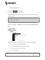
Installing A New SIM Card 22
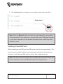
Reset and Erase 23
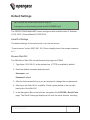
Initial Settings 24
Default Settings 25
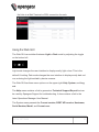
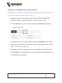
Using the Web GUI 26
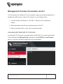
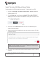
Management Console Connection via CLI 28
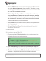
Accessing the Web GUI CLI Terminal 28
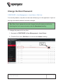
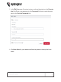
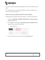
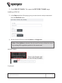
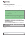
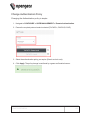
Change the Root Password 29

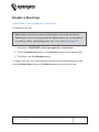
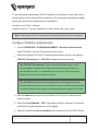
Disable a Root User 31
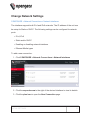
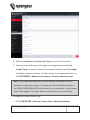
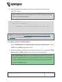
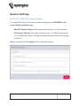
Change Network Settings 32
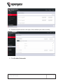
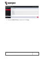
MONITOR Menu 36
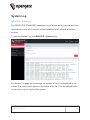
System Log 37
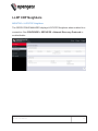
LLDP CDP Neighbors 38
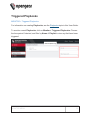
Triggered Playbooks 39
ACCESS Menu 40
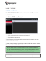
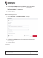
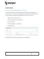
Local Terminal 41
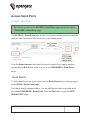
Access Serial Ports 42
Quick Search 42
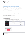
Access Using Web Terminal or SSH 43
Serial Port Logging 43
CONFIGURE Menu 45
Configure Serial Ports 46
Edit Serial Ports 47
Autodiscovery 49
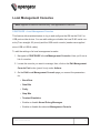
Local Management Consoles 51
Lighthouse Enrollment 53
Manual Enrollment Using UI 54
Manual Enrollment Using the CLI 55
Playbooks 56
Create Or Edit a Playbook 56
PDUs 61
Add and Configure a PDU 61
PDU Operation 63
SNMP Alerts 64
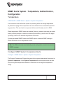
SNMP Alerts System - Temperature, Authentication, Configuration 65

Temperature 65
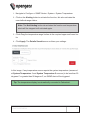
Configure SNMP System Temperature Alerts 65
Authentication 67
Configuration 67
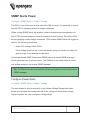
SNMP Alerts Power 68
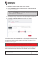
Configure Power Alerts 68
SNMP Alerts Networking (Connection Status) 70
Configure Signal Strength Alerts 70
Network Connections 72
Network Interfaces 73
Dual SIM 74
Display SIM Status and Signal Strength 74
Installing A New SIM Card 76
Select The Active SIM (Manual Failover Mode) 77
Select The Primary SIM (Automatic Failover Mode) 78
Dual SIM Automatic Failover 80
Failover Modes 82
Activate or Configure Automatic Failover 83
Cellular Interface Policy Settings 84
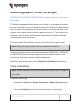
Network Aggregates - Bonds and Bridges 86
Create A New Bridge 86
Edit an Existing Bridge 87
Edit Bridge - Form Definitions 88
Create A New Bond 89
Edit an Existing Bond 89
Edit Bond - Form Definitions 90
Spanning Tree Protocol 92
Enable STP in a Bridge 93
Bridge With STPEnabled - UI 93
Bridge With STPEnabled - OGCLI 93
Bridge With STPDisabled - OGCLI 94

IPsec Tunnels 95
Create, Add or Edit IPsec Tunnels 95
Network Resilience 100
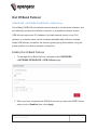
Out Of Band Failover 101
Enable Out-of-Band Failover 101
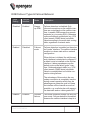
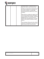
OOB Failover Types & Failover Behavior 102
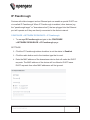
IP Passthrough 104
User Management 106
Groups 107
Create a New Group 107
Edit an Existing Group 109
Local Users 111
Create a New User With Password 112
Create a New User With No Password (Remote Authentication) 113
Modify An Existing User Account With Password 113
Manage SSH Authorized Keys for a User Account 114
Delete a User's Account 115
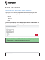
Remote Authentication 116
Configure RADIUS Authentication 117
Configure TACACS+ Authentication 118
Configure LDAP Authentication 119
RemoteLocal for AAA Server 121
Change Authentication Policy 122
Authentication Scenarios 123
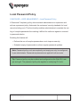
Local Password Policy 124
Set Password Complexity Requirements 125
Set Password Expiration Interval 126
Password Policy Implementation Rules 127
Services 129
HTTPS Certificate 130

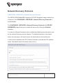
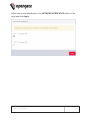
Network Discovery Protocols 132
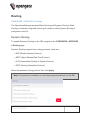
Routing 134
Dynamic Routing 134
Static Routing (via the ogcli) 135
SSH 137
Unauthenticated SSH to Serial Ports 138
Enable Unauthenticated SSH 138
Enable SSH 139
Enable/Disable 139
Connecting Directly to Serial Ports 140
Feature Persist 141
Properties and Settings 141
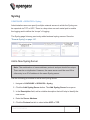
Syslog 144
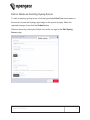
Add a New Syslog Server 144
Global Serial Port Settings 145
Edit or Delete an Existing Syslog Server 146
Remote Syslog 147
Remote Syslog Requirements 147
Remote Syslog Server Logging Levels 148
Port Logging Levels 148
Global Serial Port Settings 148
Edit or Delete an Existing Syslog Server 148
Create Syslog Server Tab - Field Definitions 149
Syslog Facility Definitions 150
Syslog Severity Definitions 151
Session Settings 152
Firewall 153
Firewall Management 154
Firewall Management Main Page 154
Firewall Zone Settings 155
Port Forwarding 155

Manage Custom Rules 156
Interzone Policies 157
Create an Interzone Policy 157
Edit or Delete an Interzone Policy 159
Customized Zone Rules 159
Firewall 160
Date & Time 161
Time Zone 162
Manual Settings 163
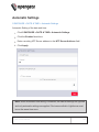
Automatic Settings 164
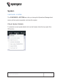
System 165
Check System Details 165
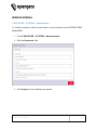
Administration 166
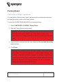
Factory Reset 167
Reboot 168
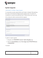
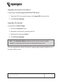
System Upgrade 169
Upgrade Via Fetch From Server 170
Upgrade Via Upload 170
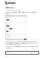
SNMP 171
SNMP Service 172
SNMP Alert Managers 173
Multiple SNMP Alert Managers 174
Create or Delete an SNMPManager 174
New SNMP Alert Manager Page Definitions 175
Advanced Options 177
Communicating With The Cellular Modem 178
OGCLI Guide 180
Commands For Exploring ogcli Usage 180
ogcli Sub Commands 181


Copyright ©
Opengear Inc. 2021. All Rights Reserved.
Information in this document is subject to change without notice and does not rep-
resent a commitment on the part of Opengear. Opengear provides this document
“as is,” without warranty of any kind, expressed or implied, including, but not limited
to, the implied warranties of fitness or merchantability for a particular purpose.
Opengear may make improvements and/or changes in this manual or in the product
(s) and/or the program(s) described in this manual at any time. This product could
include technical inaccuracies or typographical errors. Changes are periodically
made to the information herein; these changes may be incorporated in new editions
of the publication.
COPYRIGHT © 9

Safety & FCC Statement
Safety Statement
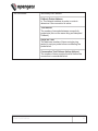
Please take care to follow the safety precautions below when installing and oper-
ating the OPERATIONS MANAGER:
lDo not remove the metal covers. There are no operator serviceable com-
ponents inside. Opening or removing the cover may expose you to dangerous
voltage which may cause fire or electric shock. Refer all service to Opengear
qualified personnel.
lTo avoid electric shock the power cord protective grounding conductor must
be connected through to ground.
lAlways pull on the plug, not the cable, when disconnecting the power cord
from the socket.
Do not connect or disconnect the appliance during an electrical storm. Also use a
surge suppressor or UPS to protect the equipment from transients.
FCC Warning Statement
This device complies with Part 15 of the FCC rules. Operation of this device is sub-
ject to the following conditions: (1) This device may not cause harmful interference,
and (2) this device must accept any interference that may cause undesired oper-
ation.
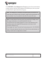
Proper back-up systems and necessary safety devices should be utilized to
protect against injury, death or property damage due to system failure. Such
protection is the responsibility of the user.
SAFETY & FCC STATEMENT 10

This device is not approved for use as a life-support or medical system.
Any changes or modifications made to this device without the explicit
approval or consent of Opengear will void Opengear of any liability or
responsibility of injury or loss caused by any malfunction.
This equipment is for indoor use and all the communication wiring are limited
to inside of the building.
SAFETY & FCC STATEMENT 11

About This User Guide
This user guide covers the Opengear Operation Manager products, including the
OM2200 family of rack-mountable appliances (available with combinations of up to
48 serial ports and 24 Ethernet ports) and the OM1200 family of small form-factor
appliances (available with combinations up to 8 serial and 8 Ethernet ports).
This manual is up to date for the 21.Q2 May 2021 firmware release. When using a
minor release there may or may not be a specific version of the user guide for that
release. The current Operations Manager user guide can always be found here.
ABOUT THIS USER GUIDE 12

Installation And Connection
This section describes how to install the appliance hardware and connect it to con-
trolled devices.
INSTALLATION AND CONNECTION 13

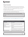
Power Connection
OM2200 and some newer OM1200 have dual power inlets with auto failover built
in. These power supplies each accept AC input voltage between 100 and 240 VAC
with a frequency of 50 or 60 Hz. The OM2224-24E-10G-L draws a maximum of
48W, while non-24E are less than 30W.
Two IEC AC power sockets are located on the power side of the metal case, and
these IEC power inlets use conventional IEC AC power cords.
Note: Country specific IEC power cords are not included with OM2200s.
OM1200s are shipped with a 12VDC to universal AC (multi-country clips) wall
adapter.
See also "Dual AC Supply" on page16 and "SNMP Alerts Power" on page68.
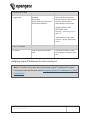
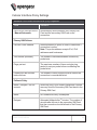
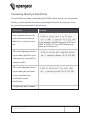
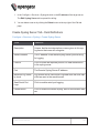
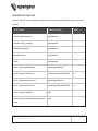
Operations Manager Platform (OM1200) Environmental And Power
Power Draw < 25 Watts
Operating conditions Temperature 0~50C, Rel Humidity 5~90%
Cooling Passive
Environmental Sensors Smart Controller with multi-zone temperature
sensors.
Auto-shutdown/re-boot on severe thermal events
Power Draw Sensors Active multi-zone power draw monitoring
INSTALLATION AND CONNECTION 14

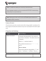
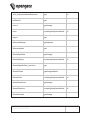
Operations Manager Platform (OM2200) Environmental And Power
Power Supply Dual AC or dual DC
Power Draw 48 Watts for -24E, others <30W
Operating conditions Temperature 0~50C, Rel Humidity 5~90%
Cooling Passive
Environmental Sensors Smart Controller with multi-zone temperature
sensors
Supervisory environmental controller with safety
power down.
Power Draw Sensors Active multi-zone power draw monitoring
INSTALLATION AND CONNECTION 15

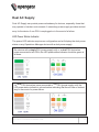
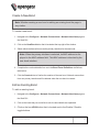
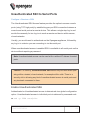
Dual AC Supply
Dual AC Supply can provide power redundancy for devices, especially those that
may operate in harsher environments. A secondary power supply provides redund-
ancy for the device if one PSU is unplugged or in the event of a failure.
LED Power Status Indicator
The power LED indicator requires no configuration and will display the dual power
status on any Operations Manager device with a dual power supply.
On a device with a single PSU (power supply unit) or, a dual PSU device has
power connected to two PSUs, the LED power status indicator should be green at
all times.
If a dual PSU device has power connected to one PSU (power supply unit), the
LED power status indicator is colored amber indicating that the unit has no redund-
ancy in the event of a power failure.
INSTALLATION AND CONNECTION 16

SNMP Alerts for Power-related Events
The System Voltage Range SNMP alert is triggered when there is a change in
power status such as a system reboot or when the voltage on either power supply
leaves or enters the configured range of the System Voltage alert.
SNMP Alert Configuration
The System Voltage Range SNMP alert is configured in the Configure > SNMP
Alerts page, see "SNMP Alerts Power" on page68.
INSTALLATION AND CONNECTION 17

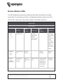
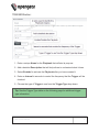
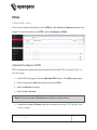
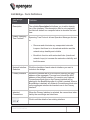
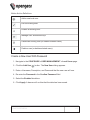
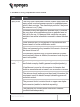
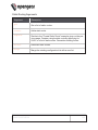
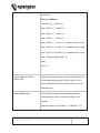
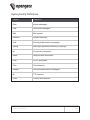
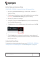
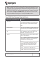
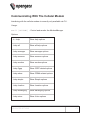
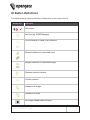
Device Status LEDs
The LED states shown below are determined through infod status and config-
server data. The config server holds a configurable threshold value for the Cell
LED Amber / Green light, and modem enabled / disabled information.
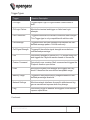
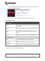
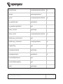
Status LEDs
LED Condition
LED Off Amber
Flashing Amber Solid Green
Flashing Green Solid
Power Device is off. On a dual
power supply
system:
Only one PSU
is connected.
On a single
power supply
system:
power is con-
nected.
On a dual
power supply
system:
Redundant
power is con-
nected.
Heartbeat Device has hal-
ted.
Device is
booting.
Normal
operation.
Device is
halted.
Network No active net-
work con-
nection
Device is
failover start-
ing.
Device is in fail-
over.
Normal network
connection is
stopping or nor-
mal network is
up and failover
is stopping.
Network is
connected.
INSTALLATION AND CONNECTION 18

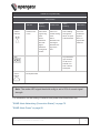
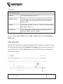
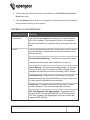
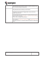
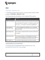
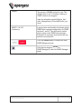
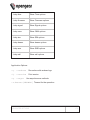
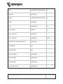
Status LEDs (continued).
LED Condition
LED Off Amber
Flashing Amber Solid Green
Flashing Green Solid
Cellular
Interface
Cellular is not
in use.
Cell is start-
ing and sig-
nal is
below
threshold.
The LED
signal
threshold
config is set
to 50%.
Cell is con-
nected and sig-
nal is
below
threshold. The
LED signal
threshold con-
fig is set to
50%.
Cell is starting
and signal is
above, or equal
to the threshold.
Cell is con-
nected and
signal is
above, or
equal to the
threshold.
IOIO Any serial activ-
ity is received,
on either con-
sole/usb con-
sole or device
serial ports.
Cloud /
Internet
Not implemented.
Note: The amber LED signal threshold config is set to 50%.of normal signal
strength.
For information on the setting of network and power alert thresholds, see:
"SNMP Alerts Networking (Connection Status)" on page70
"SNMP Alerts Power" on page68
INSTALLATION AND CONNECTION 19

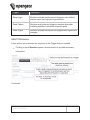
Connecting to the Network
All Operations Manager products have two network connections labeled NET1 and
NET2. In the OM2200, there are options for copper wiring (on a standard RJ-45 con-
nector) and fiber (through a standard SFP module).
The network connections on the OM2200 are located on the serial port side of the
unit. Connect the provided shielded CAT5 cable to the NET1 to a computer or into
your network for initial configuration. By default NET1 and NET2 are enabled.
You can use either 10/100/1000BaseT over Cat5 or fiber-optical transceiver
(1Gbps) in the SFP slot for NET1 or NET2 on OM2200 (non-10G) and OM1208-8E.
INSTALLATION AND CONNECTION 20
Page is loading ...
Page is loading ...
Page is loading ...
Page is loading ...
Page is loading ...
Page is loading ...
Page is loading ...
Page is loading ...
Page is loading ...
Page is loading ...
Page is loading ...
Page is loading ...
Page is loading ...
Page is loading ...
Page is loading ...
Page is loading ...
Page is loading ...
Page is loading ...
Page is loading ...
Page is loading ...
Page is loading ...
Page is loading ...
Page is loading ...
Page is loading ...
Page is loading ...
Page is loading ...
Page is loading ...
Page is loading ...
Page is loading ...
Page is loading ...
Page is loading ...
Page is loading ...
Page is loading ...
Page is loading ...
Page is loading ...
Page is loading ...
Page is loading ...
Page is loading ...
Page is loading ...
Page is loading ...
Page is loading ...
Page is loading ...
Page is loading ...
Page is loading ...
Page is loading ...
Page is loading ...
Page is loading ...
Page is loading ...
Page is loading ...
Page is loading ...
Page is loading ...
Page is loading ...
Page is loading ...
Page is loading ...
Page is loading ...
Page is loading ...
Page is loading ...
Page is loading ...
Page is loading ...
Page is loading ...
Page is loading ...
Page is loading ...
Page is loading ...
Page is loading ...
Page is loading ...
Page is loading ...
Page is loading ...
Page is loading ...
Page is loading ...
Page is loading ...
Page is loading ...
Page is loading ...
Page is loading ...
Page is loading ...
Page is loading ...
Page is loading ...
Page is loading ...
Page is loading ...
Page is loading ...
Page is loading ...
Page is loading ...
Page is loading ...
Page is loading ...
Page is loading ...
Page is loading ...
Page is loading ...
Page is loading ...
Page is loading ...
Page is loading ...
Page is loading ...
Page is loading ...
Page is loading ...
Page is loading ...
Page is loading ...
Page is loading ...
Page is loading ...
Page is loading ...
Page is loading ...
Page is loading ...
Page is loading ...
Page is loading ...
Page is loading ...
Page is loading ...
Page is loading ...
Page is loading ...
Page is loading ...
Page is loading ...
Page is loading ...
Page is loading ...
Page is loading ...
Page is loading ...
Page is loading ...
Page is loading ...
Page is loading ...
Page is loading ...
Page is loading ...
Page is loading ...
Page is loading ...
Page is loading ...
Page is loading ...
Page is loading ...
Page is loading ...
Page is loading ...
Page is loading ...
Page is loading ...
Page is loading ...
Page is loading ...
Page is loading ...
Page is loading ...
Page is loading ...
Page is loading ...
Page is loading ...
Page is loading ...
Page is loading ...
Page is loading ...
Page is loading ...
Page is loading ...
Page is loading ...
Page is loading ...
Page is loading ...
Page is loading ...
Page is loading ...
Page is loading ...
Page is loading ...
Page is loading ...
Page is loading ...
Page is loading ...
Page is loading ...
Page is loading ...
Page is loading ...
Page is loading ...
Page is loading ...
Page is loading ...
Page is loading ...
Page is loading ...
Page is loading ...
Page is loading ...
Page is loading ...
Page is loading ...
Page is loading ...
Page is loading ...
Page is loading ...
Page is loading ...
Page is loading ...
Page is loading ...
Page is loading ...
Page is loading ...
Page is loading ...
Page is loading ...
Page is loading ...
Page is loading ...
Page is loading ...
Page is loading ...
Page is loading ...
Page is loading ...
Page is loading ...
Page is loading ...
Page is loading ...
Page is loading ...
Page is loading ...
Page is loading ...
Page is loading ...
-
 1
1
-
 2
2
-
 3
3
-
 4
4
-
 5
5
-
 6
6
-
 7
7
-
 8
8
-
 9
9
-
 10
10
-
 11
11
-
 12
12
-
 13
13
-
 14
14
-
 15
15
-
 16
16
-
 17
17
-
 18
18
-
 19
19
-
 20
20
-
 21
21
-
 22
22
-
 23
23
-
 24
24
-
 25
25
-
 26
26
-
 27
27
-
 28
28
-
 29
29
-
 30
30
-
 31
31
-
 32
32
-
 33
33
-
 34
34
-
 35
35
-
 36
36
-
 37
37
-
 38
38
-
 39
39
-
 40
40
-
 41
41
-
 42
42
-
 43
43
-
 44
44
-
 45
45
-
 46
46
-
 47
47
-
 48
48
-
 49
49
-
 50
50
-
 51
51
-
 52
52
-
 53
53
-
 54
54
-
 55
55
-
 56
56
-
 57
57
-
 58
58
-
 59
59
-
 60
60
-
 61
61
-
 62
62
-
 63
63
-
 64
64
-
 65
65
-
 66
66
-
 67
67
-
 68
68
-
 69
69
-
 70
70
-
 71
71
-
 72
72
-
 73
73
-
 74
74
-
 75
75
-
 76
76
-
 77
77
-
 78
78
-
 79
79
-
 80
80
-
 81
81
-
 82
82
-
 83
83
-
 84
84
-
 85
85
-
 86
86
-
 87
87
-
 88
88
-
 89
89
-
 90
90
-
 91
91
-
 92
92
-
 93
93
-
 94
94
-
 95
95
-
 96
96
-
 97
97
-
 98
98
-
 99
99
-
 100
100
-
 101
101
-
 102
102
-
 103
103
-
 104
104
-
 105
105
-
 106
106
-
 107
107
-
 108
108
-
 109
109
-
 110
110
-
 111
111
-
 112
112
-
 113
113
-
 114
114
-
 115
115
-
 116
116
-
 117
117
-
 118
118
-
 119
119
-
 120
120
-
 121
121
-
 122
122
-
 123
123
-
 124
124
-
 125
125
-
 126
126
-
 127
127
-
 128
128
-
 129
129
-
 130
130
-
 131
131
-
 132
132
-
 133
133
-
 134
134
-
 135
135
-
 136
136
-
 137
137
-
 138
138
-
 139
139
-
 140
140
-
 141
141
-
 142
142
-
 143
143
-
 144
144
-
 145
145
-
 146
146
-
 147
147
-
 148
148
-
 149
149
-
 150
150
-
 151
151
-
 152
152
-
 153
153
-
 154
154
-
 155
155
-
 156
156
-
 157
157
-
 158
158
-
 159
159
-
 160
160
-
 161
161
-
 162
162
-
 163
163
-
 164
164
-
 165
165
-
 166
166
-
 167
167
-
 168
168
-
 169
169
-
 170
170
-
 171
171
-
 172
172
-
 173
173
-
 174
174
-
 175
175
-
 176
176
-
 177
177
-
 178
178
-
 179
179
-
 180
180
-
 181
181
-
 182
182
-
 183
183
-
 184
184
-
 185
185
-
 186
186
-
 187
187
-
 188
188
-
 189
189
-
 190
190
-
 191
191
-
 192
192
-
 193
193
-
 194
194
-
 195
195
-
 196
196
-
 197
197
-
 198
198
-
 199
199
-
 200
200
-
 201
201
-
 202
202


Opengear OperationsManager Owner's manual
- Category
- Networking
- Type
- Owner's manual
Ask a question and I''ll find the answer in the document
Finding information in a document is now easier with AI
Related papers
-
 Opengear OperationsManager Owner's manual
-
 Opengear OperationsManager User manual
-
 Opengear CM8100 User guide
-
 Opengear CM8100 User guide
-
 Opengear CM8100 Owner's manual
-
 Opengear OM2200 Quick start guide
-
 Opengear OM Owner's manual
-
 Opengear ACM7000-LMx Quick start guide
-
 Opengear OpenGear User manual
-
Opengear OM1204 User guide


Other documents
-
 StarTech.com PDU02IP User manual
-
Tripp Lite B093-, B097- & B098-Series Console Servers Owner's manual
-
Lantronix Network Hardware 900-598 User manual
-
Cradlepoint CBA850 User manual
-
Cradlepoint AER3100 Series User manual
-
-
Juniper Contrail Networking Installation and Upgrade Guide
-
-
Cradlepoint COR IBR1100 Series User manual
-
Dell PowerConnect 7024P Owner's manual
