Page is loading ...

Page 1
507777-03
01/2021
INSTALLATION INSTRUCTIONS FOR REPLACEMENT HEAT EXCHANGER KITS FOR USE WITH
ML196UHE AND EL196UHE FURNACES
REPLACEMENT HEAT
EXCHANGER
GAS UNITS
KITS & ACCESSORIES
WARNING
Improper installation, adjustment, alteration, service
or maintenance can cause property damage, personal
injury or loss of life. Installation and service must be
performed by a licensed professional installer (or
equivalent), service agency or the gas supplier.
WARNING
Disconnect power before servicing unit.
Shipping and Packing List
Package 1 of 1 contains:
1 - Heat exchanger assembly
1 - Condensate trap parts bag
1 - Pressure Switch (Provided in 20L52 only)
CAUTION
As with any mechanical equipment, personal injury can
result from contact with sharp sheet metal edges. Be
careful when you handle this equipment.
Installation - Upow / Horizontal Furnaces
Refer to gure 1 as you disassemble the unit. See table 1
for unit capacity and matching kit. Place papers or protec-
tive covering in front of the furnace before removing the
heat exchanger assembly.
TABLE 1
Model Cat. No. Kit
EL/ML196UH030XE36B 614580-01 12Y77
EL/ML196UH045XE36B 614580-63 16H67
EL/ML196UH070XE36B 614580-75 20L52*
ML196UH070XE48B 614580-75 20L52*
ML196UH090XE36C 614580-76 20L96
EL/ML196UH090XE48C 614580-67 16U74
ML196UH090XE60C 614580-76 20L96
EL/ML196UH110XE60C 614580-69 16U76
ML196UH135XE60D 614580-77 20L99
* Pressure switch provided in 20L52 is only applicable for altitudes
0-4500’. A high altitude kit must be orered for installation greater than
4500’.
1 - Turn o electrical and gas supplies to the furnace.
2 - Remove the furnace access panels.
3 - Disconnect the wires from the gas valve.
4 - Remove gas supply line connected to gas valve.
5 - Remove the burner box cover (if equipped) and
remove gas valve/manifold assembly.
6 - Remove sensor wire from sensor. Disconnect 2-pin
plug from the ignitor.
7 - Disconnect wires from ame roll-out switches. On
some models, disconnect ground wire from burner
box mounting lug.
8 - Disconnect combustion air intake pipe. It may be
necessary to cut the existing pipe to remove burner
box assembly.
9 - Remove four burner box screws at the vestibule
panel and remove burner box. Set burner box
assembly aside.
NOTE - If necessary, clean burners at this time.
Follow procedures outlined in Burner Cleaning
section.
10 - Loosen the clamps to the exible exhaust coupling.
11 - Disconnect condensate drain line from the cold end
header box.
12 - Disconnect condensate drain tubing from ue collar
and cold end header box (tubing will be re-used, set
aside). Remove screws that secures the ue collar
into place. Remove ue collar. It may be necessary
to cut the exiting exhaust pipe for removal of the
tting.
13 - Mark and disconnect all combustion air pressure
tubing from cold end header collector box.
14 - Mark and remove wires from pressure switch
assembly. Remove the assembly. Keep tubing
attached to the pressure switch.
15 - Disconnect the plug from the combustion air inducer.
Remove two screws which secure combustion air
inducer to collector box. Remove combustion air
inducer assembly.
16 - Remove electrical junction box from the side of the
furnace.
17 - Mark and disconnect any remaining wiring to
heating compartment components. Disengage
strain relief bushing and pull wiring and bushing
through the hole in the blower deck.
©2021

Page 2
18 - Remove the primary limit from the vestibule panel.
19 - Remove two screws from the front cabinet ange at
the blower deck.
20 - Remove screws along vestibule sides and bottom
which secure vestibule panel and heat exchanger
assembly to cabinet. Remove two screws from
blower rail which secure bottom heat exchanger
ange. Spread cabinet sides slightly to allow
clearance for removal of heat exchanger. Remove
heat exchanger from furnace cabinet.
21 - Remove indoor blower from the furnace.
22 - Install replacement heat exchanger into the cabinet..
23 - Secure Heat exchanger to the blower deck using
two #8 screws through blower deck rst. See gure
2.
24 - Re-secure the supporting screws along the vestibule
sides and bottom to the cabinet.
25 - Reinstall cabinet screws on front ange at blower
deck.
26 - Reinstall the primary limit on the vestibule panel.
27 - Route heating component wiring through hole in
blower deck and reinsert strain relief bushing.
28 - Reinstall electrical junction box.
29 - Reinstall the combustion air inducer. Reconnect the
plug to the wire harness.
30 - Reinstall pressure switches and reconnect pressure
switch wiring. The pressure switch may be need to
be replaced with provided switch in kit. See packing
list and table 1 for applicable models.
31 - Carefully connect combustion air pressure switch
tubing from pressure switches to proper ports on
cold end header collector box.
32 - Reconnect condensate drain line to the cold end
header box.
33 - Use securing screws to reinstall ue collar to the
top cap on the furnace. Reconnect exhaust piping
and exhaust drain tubing to ue collar and cold end
header box.
34 - Replace exible exhaust adapter on combustion air
inducer and ue collar. Secure using two existing
hose clamps.
35 - Reinstall burner box assembly in vestibule area.
Secure burner box assembly to vestibule panel using
four existing screws. Make sure burners line up with
center of heat exchanger inlets.
36 - Reconnect ame roll-out switch wires. If removed
from step 6, reconnect the ground wire to the burner
box mounting lug.
37 - Reconnect sensor wire and reconnect 2-pin plug
from ignitor.
38 - Reinstall gas valve manifold assembly. Reconnect
gas supply line to gas valve.
39 - Reconnect the combustion air intake pipe.
40 - Reinstall burner box cover (if equipped).
41 - Reconnect wires to gas valve.
42 - Replace the blower compartment access panel.
43 - Reconnect gas supply piping. Turn on power and
gas supply to unit.
44 - Follow lighting instructions on unit nameplate to
light and operate furnace for 5 minutes to ensurethe
furnace is operating properly.
45 - Check all piping connections, factory and eld, for
gas leaks. Use a leak detecting solution or other
preferred means.
46 - Replace heating compartment access panel.
CAUTION
Some soaps used for leak detection are corrosive to
certain metals. Carefully rinse piping thoroughly after
leak test has been completed. Do not use matches,
candles, ame or other sources of ignition to check for
gas leaks.
Cleaning the Burner Assembly (if needed)
1 - Turn o electrical and gas power supplies to furnace.
Remove upper and lower furnace access panels.
2 - Disconnect the wires from the gas valve.
3 - Remove the burner box cover (if equipped).
4 - Mark and disconnect sensor wire from the sensor
and disconnect the 2-pin plug to the igniter.
Disconnect wires from ame rollout switches.
5 - Disconnect the gas supply line from the gas valve.
Remove gas valve/manifold assembly.
6 - Disconnect combustion air intake pipe. It may be
necessary to cut the existing pipe to remove burner
box assembly.
7 - Remove four screws which secure burner box
assembly to vest panel. Remove burner box from
the unit.
8 - Use the soft brush attachment on a vacuum cleaner
to gently clean the face of the burners. Visually
inspect the inside of the burners and crossovers for
any blockage caused by foreign matter. Remove
any blockage.
9 - Reinstall the burner box assembly using the existing
four screws. Make sure that the burners line with
center of heat exchanger inlets.
10 - Reinstall the gas valve manifold assembly.
Reconnect the gas supply line to the gas valve.
11 - Reconnect the sensor wire and reconnect the 2-pin
plug to the ignitor wiring harness. Reconnect wires
to ame rollout switches.
12 - Reinstall the burner box cover (if equipped).
13 - Reconnect wires to gas valve.
14 - Replace the blower compartment access panel.
15 - Refer to instruction on verifying gas and electrical
connections when re-establishing supplies.
16 - Follow lighting instructions to light and operate
furnace for 5 minutes to ensure that heat exchanger
is clean and dry and that furnace is operating
properly.
17 - Replace heating compartment access panel.

Page 3
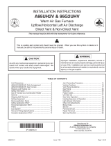
UPFLOW/HORIZONTAL PARTS IDENTIFICATION
TOP CAP
BURNER BOX
ASSEMBLY
HEAT EXCHANGER
ASSEMBLY
COMBUSTION AIR
INDUCER
OUTER
ACCESS
PANEL
COMBUSTION
AIR PRESSURE
SWITCH
PRIMARY LIMIT
GAS VALV E
BLOWER
ASSEMBLY
COLD END
HEADER BOX
BLOWER ACCESS
PANEL
Figure 1
HEAT EXCHANGER WITH BLOWER DECK
#8 Screws
Figure 2
/