
Page 1
508205-01
08/ 2021
INSTALLATION INSTRUCTIONS FOR NATURAL GAS ORIFICE KITS (22P38, 22P39, 22P40 & 20P41) USED WITH
80% AND 90% EFFICIENCY ULTRA LOW NOX UNITS
GAS ORIFICE KIT
GAS UNITS
KITS & ACCESSORIES
WARNING
This kit is to be installed by a licensed professional
service technician (or equivalent) or other qualied
agency in accordance with the manufacturer’s
instructions, all codes and requirements of the authority
having jurisdiction in the USA, and the requirements
of the CSA-B149 installation codes in Canada. If the
information in these instructions is not followed exactly,
a re or explosion may result causing property damage,
personal injury or loss of life. The qualied agency
performing this work assumes responsibility for this
conversion.
CAUTION
As with any mechanical equipment, contact with
sharp sheet metal edges can result in personal
injury. Take care while handling this equipment and
wear gloves and protective clothing.
Shipping and Packing List
Package 1 of 1 contains:
1 - Gas orice
1 - Instruction
1 - Label
Application
Conrm the kit received is correct for the Ultra Low NOx
furnace being serviced, based on the information provided
in Table 1.
TABLE 1
Unit
Capacity
Gas Orice
80% 90%
-040 22P39 22P38
-060 22P39
-080 22P40
-100 22P41
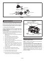
Installation Figure 1
1 - Set the thermostat to the lowest setting. Shut o the
gas supply to the furnace, then turn o the electrical
power at the unit disconnect switch.
2 - Remove the access panel. Move the automatic gas
valve switch to the OFF position.
3 - Disconnect the gas supply from the gas valve.
Disconnect the two-wire plug at the gas valve.
4 - Remove the four screws that hold the gas-air elbow
to the gas-air collector hot box.
5 - Loosen the clamp attaching the intake to the gas-air
elbow. Remove the intake from the gas-air elbow.
6 - Use a socket wrench to remove the gas orice from
inside of the manifold pipe. Replace with provided
gas orice. DO NOT USE sealant on orice.
7 - Reconnect two-wire plug to the gas vale.
8 - Reconnect electrical power to the unit.
9 - Inspect all sides of assembly. Turn on gas supply.
10 - Immediately check the entire tting surface
andassembly joints for gas leaks.
11 - Follow the steps given in the start-up and adjustment
section.
©2021

Page 2
Gas Valve
Debri Screen
Air Orifice
Gas Air Elbow
Clamp
Thermal Switch
(location)
Gas Orifice
(inside)
Manifold Pipe
FIGURE 1
Start-Up & Adjustment
BEFORE PLACING THE UNIT INTO OPERATION -
Smell all around the appliance area for gas. Use only your
hand to move the gas control switch. Never use tools. If
the switch will not move by hand, do not try to repair it.
Force or attempted repair may result in a re or explosion.
A - Placing the Unit into Operation
Follow the lighting instructions provided on the unit.
If lighting instructions are not available, refer to the
following section.
Units are equipped with an integrated ignition system. The
integrated ignition control automatically lights the burners
each time the thermostat calls for heat.
1 - STOP! Read the safety information at the beginning
of this section.
2 - Set the thermostat to its lowest setting.
3 - Turn o all electrical power to the furnace.
4 - Do not try to light the burners by hand.
5 - Remove the unit access panel.
6 - Move the switch on the gas valve to OFF. Do not
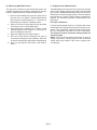
force the switch. See gure 2.
7 - Wait ve (5) minutes for any gas to clear out. If you
then smell gas, STOP! Immediately call your gas
supplier from a neighbor’s phone. Follow the gas
supplier’s instructions. If you do not smell gas, go
to the next step.
8 - Move the switch on the gas valve to ON.
9 - Replace the unit compartment access panel.
10 - Turn on all electrical power to the unit.
11 - Set the thermostat to desired setting.
12 - If the furnace will not operate, see section E- “Turning
Gas O to the Unit” and call the gas supplier.
GAS VALVE
NEGATIVE AIR
PRESSURE PORT POSITIVE AIR
PRESSURE PORT
MANIFOLD
PRESSURE TAP
TELTUOTELNI
SUPPLY
PRESSURE
TAPGAS VALVE SHOWN IN THE ON POSITION
MANIFOLD ADJUSTMENT
(TURN CCW TO INCREASE PRESSURE)
FIGURE 2
Gas Pressure Measurement
A - Gas Flow (Approximate)
NOTE - To obtain accurate reading, shut o all other gas
appliances connected to meter.
Furnace should operate at least 5 minutes before check-
ing gas ow. Determine time in seconds for two revolu-
tions of gas through the meter. (Two revolutions assures
a more accurate time.) Divide by two and compare to
time in table provided in the unit installation instruction.If
manifold pressure matches the manifold table in the unit
installation instructions and rate is incorrect, check gas
orices for proper size and restriction. Remove temporary
gas meter if installed.

Page 3
B - Measuring Manifold Pressure
The gas valve is factory set and should not require ad-
justment. All gas valves are factory regulated. To correctly
measure manifold pressure, follow the steps below:
1 - Remove the threaded plug from the outlet side of
the gas valve and install a eld-provided barbed
tting. Connect measuring device “+” connection to
barbed tting to measure manifold pressure.
2 - Start unit on low heat (two stage furnace) and allow
5 minutes for unit to reach steady state.
3 - After allowing unit to stabilize for 5 minutes, record
manifold pressure and compare to value given in
the unit installation instruction.
4 - Repeat on high heat (two stage furnace)
5 - Shut unit o and remove manometer as soon as
an accurate reading has been obtained. Take care
to remove barbed tting and replace threaded plug.
6 - Start unit and perform leak check. Seal leaks if
found.
C - Supply Pressure Measurement
A threaded plug on the inlet side of the gas valve provides
access to the supply pressure tap. Remove the threaded
plug, install a eld-provided barbed tting and connect a
manometer to measure supply pressure. See unit installa-
tion instruction for correct supply pressure measurement.
Replace the threaded plug after measurements have
been taken.
D- Proper Combustion
Furnace should operate minimum 15 minutes with correct
manifold pressure and gas ow rate before checking com-
bustion. Take combustion sample beyond the ue outlet.
See unit installation instruction for correct combustion.
The maximum carbon monoxide reading should not
exceed 100 ppm.
NOTE - Shut unit o and remove manometer as soon as
supply line pressure, manifold pressure and combustion
sample have been obtained. Take care to replace pres-
sure tap plug.
-
 1
1
-
 2
2
-
 3
3


Ask a question and I''ll find the answer in the document
Finding information in a document is now easier with AI
Related papers
-
Lennox Gas Changeover Kit Installation guide
-
-
-
-
-
-
-
-
-
Lennox ML18013560D-EC Installation Instructions Manual
Other documents
-
Allied A80UH User manual
-
ROYALTON 80G1DF045AP12 Installation guide
-
COMFORT-AIRE GDD80A070A3M-CY Installation and Operation Manual
-
-
-
-
Lennox International Inc. ML180UH User manual
-
COMFORT-AIRE GUH80C045A3M-CY Operating instructions
-
Allied 95G1E Installation guide
-