Kohler 100REZGD Operating instructions
- Category
- Power generators
- Type
- Operating instructions

Models:
10-1000 kW
Controller:
APM402/Decision-Maker
®
3000
Industrial Generator Set
TP 6694 9/20m
Operation

2 TP-6694 9/20
WARNING: This product can expose you to chemicals, including carbon monoxide and
benzene, which are known to the State of California to cause cancer and birth defects or
other reproductive harm. For more information go to www.P65warnings.ca.gov
WARNING: Breathing diesel engine exhaust exposes you to chemicals known to the
State of California to cause cancer and birth defects or other reproductive harm.
Always start and operate the engine in a well-ventilated area.
If in an enclosed area, vent the exhaust to the outside.
Do not modify or tamper with the exhaust system.
Do not idle the engine except as necessary.
For more information go to www.P65warnings.ca.gov/diesel
Product Identification Information
Product identification numbers determine service parts. Record the product identification numbers in the spaces below
immediately after unpacking the products so that the numbers are readily available for future reference. Record field-installed
kit numbers after installing the kits.
Generator Set Identification Numbers
Record the product identification numbers from the engine nameplate(s).
Model Designation _________________________________________________________
Specification Number _______________________________________________________
Serial Number: ____________________________________________________________
Controller Identification
Record the controller description from the generator set operation manual, spec sheet, or sales invoice.
Controller Description________________________________________________________
Engine Identification
Record the product identification information from the engine nameplate.
Manufacturer_________________________________________________________________
Model Designation___________________________________________________________
Serial Number_______________________________________________________________
Accessory Number
Accessory Description
Accessory Number
Accessory Description

TP-6694 9/20 3
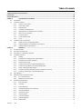
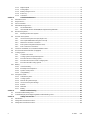
Table of Contents
Safety Precautions and Instructions ........................................................................................................................................ 7
Introduction .............................................................................................................................................................................. 13
Service Assistance................................................................................................................................................................... 15
Section 1. Specifications and Features ................................................................................................................. 17
1.1 Introduction ............................................................................................................................................................ 17
1.2 Controller Features................................................................................................................................................. 17
1.2.1 Switches and Controls ............................................................................................................................. 18
1.2.2 Annunciator Lamps .................................................................................................................................. 19
1.2.3 Digital Display .......................................................................................................................................... 21
1.2.4 Controller Fault Diagnostics ..................................................................................................................... 28
1.2.5 Digital Display Circuit Board and Connections ......................................................................................... 30
1.2.6 Main Logic Circuit Board .......................................................................................................................... 31
1.2.7 Terminal Jumper ...................................................................................................................................... 32
1.2.8 Communication Ports ............................................................................................................................... 33
1.2.9 Fuses ....................................................................................................................................................... 33
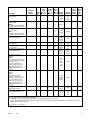
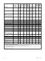
1.3 Controller Logic Specifications ............................................................................................................................... 34
1.3.1 Status Event and Fault Specifications ...................................................................................................... 35
1.3.2 Voltage Regulator and Calibration Specifications .................................................................................... 41
1.3.3 Voltage Regulator Adjustments................................................................................................................ 41
Section 2. Operation ................................................................................................................................................ 43
2.1 Prestart Checklist ................................................................................................................................................... 43
2.2 Exercising Generator Set ....................................................................................................................................... 44
2.3 Operations in Cold Weather Climates .................................................................................................................... 44
2.4 Controller Operation ............................................................................................................................................... 44
2.4.1 Starting..................................................................................................................................................... 45
2.4.2 Stopping (User Stopping and Fault Shutdown) ........................................................................................ 46
2.4.3 Emergency Stop Switch Resetting ........................................................................................................... 46
2.4.4 System Status Lamps .............................................................................................................................. 46
2.4.5 System Fault Warning Lamp with Digital Displays ................................................................................... 46
2.4.6 System Fault Shutdown Lamp with Digital Displays ................................................................................ 49
2.4.7 Status and Notice Digital Displays ........................................................................................................... 52
2.4.8 Controller Resetting (Following System Shutdown or Warning)............................................................... 54
2.4.9 Powering up the Engine Control Module (ECM) ...................................................................................... 55
2.5 Menu Displays ........................................................................................................................................................ 57
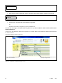
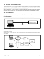
2.6 Monitoring and Programming Setup ....................................................................................................................... 59
2.6.1 PC Communications ................................................................................................................................ 59
2.6.2 Modbus® Communications ...................................................................................................................... 60
2.7 Reviewing Menu Displays ...................................................................................................................................... 60
2.7.1 Error Messages ........................................................................................................................................ 62
2.7.2 Overview .................................................................................................................................................. 63
2.7.3 Engine Metering ....................................................................................................................................... 64
2.7.4 Generator Metering (and Calibration) ...................................................................................................... 64
2.7.5 GenSet Information .................................................................................................................................. 67
2.7.6 GenSet Run Time .................................................................................................................................... 67
2.7.7 GenSet System ........................................................................................................................................ 67
2.7.8 GenSet Calibration ................................................................................................................................... 68
2.7.9 Voltage Regulator .................................................................................................................................... 70
2.7.10 Digital Inputs ............................................................................................................................................ 71

4 TP-6694 9/20
2.7.11 Digital Outputs ......................................................................................................................................... 72
2.7.12 Analog Inputs ........................................................................................................................................... 75
2.7.13 Battery Charger 1 and 2 ........................................................................................................................... 76
2.7.14 Event Log ................................................................................................................................................. 77
2.7.15 Volt Select ................................................................................................................................................ 77
Section 3. Scheduled Maintenance ........................................................................................................................ 79
3.1 Alternator Service ................................................................................................................................................... 79
3.2 Engine Service ....................................................................................................................................................... 79
3.3 Service Schedule ................................................................................................................................................... 80
3.4 Alternator Bearing Service ..................................................................................................................................... 82
3.4.1 20-300 kW Models ................................................................................................................................... 82
3.4.2 300-1000 kW Models with 4M/5M/7M Single-Bearing Alternator ............................................................. 82
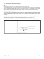
3.5 Diesel Fuel Systems............................................................................................................................................... 82
3.5.1 Bleeding Air from Fuel System ................................................................................................................. 82
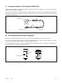
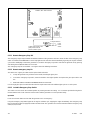
3.6 Gaseous Fuel Systems .......................................................................................................................................... 83
3.6.1 Gaseous Fuel System Concept (Single Fuel) .......................................................................................... 84
3.6.2 LPG Liquid Withdrawal Fuel System Concept ......................................................................................... 84
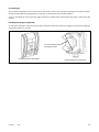
3.6.3 Natural Gas and LPG Conversion ............................................................................................................ 85
3.6.4 Fuel System Changeover Kits (Dual Fuel) ............................................................................................... 85
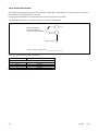
3.6.5 Fuel Conversion Connections .................................................................................................................. 86
3.7 Crankcase Ventilation (CCV) Heater Kit GM78171-KP1 ...................................................................................... 101
3.8 Air Cleaner Restrictor Indicator (if equipped) ....................................................................................................... 101
3.9 Cooling System .................................................................................................................................................... 102
3.9.1 Coolant Level Check .............................................................................................................................. 102
3.9.2 Cooling System Component Inspection ................................................................................................. 102
3.9.3 Procedure to Drain Cooling System ....................................................................................................... 103
3.9.4 Procedure to Flush and Clean Cooling System ..................................................................................... 103
3.9.5 Procedure to Refill Cooling System ....................................................................................................... 103
3.10 Battery .................................................................................................................................................................. 104
3.10.1 Clean the Battery ................................................................................................................................... 106
3.10.2 Electrolyte Level Inspection ................................................................................................................... 106
3.10.3 Specific Gravity Check ........................................................................................................................... 107
3.10.4 Charge Battery ....................................................................................................................................... 108
3.11 Storage Procedure ............................................................................................................................................... 108
3.11.1 Lubrication System ................................................................................................................................ 109
3.11.2 Cooling System ...................................................................................................................................... 109
3.11.3 Diesel Fuel System Storage................................................................................................................... 109
3.11.4 Gaseous Fuel System Storage .............................................................................................................. 109
3.11.5 Exterior................................................................................................................................................... 110
3.11.6 Alternator ............................................................................................................................................... 110
3.11.7 Battery ................................................................................................................................................... 111
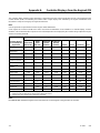
Section 4. General Troubleshooting .................................................................................................................... 113
4.1 General Troubleshooting Chart ............................................................................................................................ 114
4.2 Controller Display and Voltage Regulation Troubleshooting Chart ...................................................................... 119
Section 5. Voltage Reconnection ......................................................................................................................... 121
5.1 Introduction .......................................................................................................................................................... 121
5.2 Voltage Reconnection Procedure ......................................................................................................................... 122
5.3 Voltage Reconnection Procedure ......................................................................................................................... 123

TP-6694 9/20 5
Section 6. Accessories .......................................................................................................................................... 129
6.1 Accessories and Connections .............................................................................................................................. 129
6.1.1 Battery Chargers .................................................................................................................................... 130
6.1.2 Battery Charger Kit with Alarm Option ................................................................................................... 130
6.1.3 Common Fault/Failure (32A) Relay ........................................................................................................ 132
6.1.4 Four-Input/Fifteen-Output Module .......................................................................................................... 133
6.1.5 Gas Fuel Valve Kit ................................................................................................................................. 137
6.1.6 Two-Input/Five-Output Module ............................................................................................................... 138
6.1.7 Manual Key Switch ................................................................................................................................ 139
6.1.8 Low Fuel (Level/Pressure) Switch .......................................................................................................... 140
6.1.9 Manual Speed Adjust (Engine RPM Menu)............................................................................................ 141
6.1.10 Prime Power Switch Kit .......................................................................................................................... 141
6.1.11 Remote Emergency Stop Kit .................................................................................................................. 142
6.1.12 Remote emergency stop kit. .................................................................................................................. 142
6.1.13 Lockable Emergency Stop Switch .......................................................................................................... 142
6.1.14 Remote Reset Feature ........................................................................................................................... 144
6.1.15 Remote Serial Annunciator .................................................................................................................... 145
6.1.16 Run Relay Kit ......................................................................................................................................... 147
6.1.17 Shunt-Trip Line Circuit Breaker .............................................................................................................. 148
6.2 Accessory Connections ........................................................................................................................................ 149
Appendix A. Abbreviations ....................................................................................................................................... 155
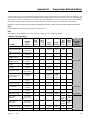
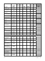
Appendix B. Programmer-Defined Settings ............................................................................................................ 159
Appendix C. Voltage Regulator Definitions and Adjustments ............................................................................... 166
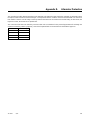
Appendix D. Alternator Protection ........................................................................................................................... 169
Appendix E. Controller Displays from the Engine ECM ......................................................................................... 170

6 TP-6694 9/20

TP-6694 9/20 7
Safety Precautions and Instructions
IMPORTANT SAFETY INSTRUCTIONS. Electromechanical equipment, including generator sets, transfer switches, switchgear,
and accessories, can cause bodily harm and pose life-threatening danger when improperly installed, operated, or maintained.
To prevent accidents be aware of potential dangers and act safely. Read and follow all safety precautions and instructions.
SAVE THESE INSTRUCTIONS.
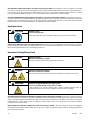
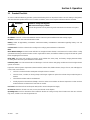
This manual has several types of safety precautions and instructions: Danger, Warning, Caution, and Notice.
DANGER
DANGER indicates a hazardous situation which, if not avoided, will result in death or serious injury.
WARNING
WARNING indicates a hazardous situation which, if not avoided, could result in death or serious injury.
CAUTION
CAUTION indicates a hazardous situation which, if not avoided, could result in minor or moderate injury.
NOTICE
NOTICE is used to address practices not related to physical injury.
Safety decals affixed to the equipment in prominent places alert the operator or service technician to potential hazards and
explain how to act safely. The decals are shown throughout this publication to improve operator recognition. Replace missing or
damaged decals.
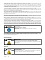
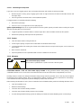
Accidental Starting
WARNING
Accidental starting.
Can cause severe injury or death.
Disconnect the battery cables before working on the generator set. Remove the
negative (–) lead first when disconnecting the battery. Reconnect the negative (–)
lead last when reconnecting the battery.
Disabling the generator set. Accidental starting can cause severe injury or death. Before working on the generator set or
equipment connected to the set, disable the generator set as follows: (1) Press the generator set off/reset button to shut down
the generator set. (2) Disconnect the power to the battery charger, if equipped. (3) Remove the battery cables, negative (–) lead
first. Reconnect the negative (–) lead last when reconnecting the battery. Follow these precautions to prevent the starting of the
generator set by the remote start/stop switch.
Battery
WARNING
Sulfuric acid in batteries.
Can cause severe injury or death.
Wear protective goggles and clothing. Battery acid may cause blindness and burn skin.

8 TP-6694 9/20
WARNING
Explosion.
Can cause severe injury or death.
Relays in the battery charger cause arcs or sparks.
Locate the battery in a well‐ventilated area. Isolate the battery charger from explosive
fumes.
Battery electrolyte is a diluted sulfuric acid. Battery acid can cause severe injury or death. Battery acid can cause
blindness and burn skin. Always wear splashproof safety goggles, rubber gloves, and boots when servicing the battery. Do not
open a sealed battery or mutilate the battery case. If battery acid splashes in the eyes or on the skin, immediately flush the
affected area for 15 minutes with large quantities of clean water. Seek immediate medical aid in the case of eye contact. Never
add acid to a battery after placing the battery in service, as this may result in hazardous spattering of battery acid.
Battery acid cleanup. Battery acid can cause severe injury or death. Battery acid is electrically conductive and corrosive.
Add 500 g (1 lb.) of bicarbonate of soda (baking soda) to a container with 4 L (1 gal.) of water and mix the neutralizing solution.
Pour the neutralizing solution on the spilled battery acid and continue to add the neutralizing solution to the spilled battery acid
until all evidence of a chemical reaction (foaming) has ceased. Flush the resulting liquid with water and dry the area.
Battery gases. Explosion can cause severe injury or death. Battery gases can cause an explosion. Do not smoke or permit
flames or sparks to occur near a battery at any time, particularly when it is charging. Do not dispose of a battery in a fire. To
prevent burns and sparks that could cause an explosion, avoid touching the battery terminals with tools or other metal objects.
Remove all jewelry before servicing the equipment. Discharge static electricity from your body before touching batteries by first
touching a grounded metal surface away from the battery. To avoid sparks, do not disturb the battery charger connections while
the battery is charging. Always turn the battery charger off before disconnecting the battery connections. Ventilate the
compartments containing batteries to prevent accumulation of explosive gases.
Battery short circuits. Explosion can cause severe injury or death. Short circuits can cause bodily injury and/or equipment
damage. Disconnect the battery before generator set installation or maintenance. Remove all jewelry before servicing the
equipment. Use tools with insulated handles. Remove the negative (–) lead first when disconnecting the battery. Reconnect the
negative (–) lead last when reconnecting the battery. Never connect the negative (–) battery cable to the positive (+) connection
terminal of the starter solenoid. Do not test the battery condition by shorting the terminals together.
Engine Backfire/Flash Fire
WARNING
Risk of fire.
Can cause severe injury or death.
Do not smoke or permit flames or sparks near fuels or the fuel system.
Servicing the fuel system. A flash fire can cause severe injury or death. Do not smoke or permit flames or sparks near the
carburetor, fuel line, fuel filter, fuel pump, or other potential sources of spilled fuels or fuel vapors. Catch fuels in an approved
container when removing the fuel line or carburetor.
Servicing the air cleaner. A sudden backfire can cause severe injury or death. Do not operate the generator set with the
air cleaner removed.
Combustible materials. A fire can cause severe injury or death. Generator set engine fuels and fuel vapors are flammable
and explosive. Handle these materials carefully to minimize the risk of fire or explosion. Equip the compartment or nearby area
with a fully charged fire extinguisher. Select a fire extinguisher rated ABC or BC for electrical fires or as recommended by the
local fire code or an authorized agency. Train all personnel on fire extinguisher operation and fire prevention procedures.
Combustible materials. A fire can cause severe injury or death. If using generator heaters during storage, remove
combustible materials such as covers from contact with the heater or from areas where heat could potentially cause a fire.

TP-6694 9/20 9
Exhaust System
WARNING
Carbon monoxide.
Can cause severe nausea, fainting, or death.
The exhaust system must be leakproof and routinely inspected.
Generator set operation. Carbon monoxide can cause severe nausea, fainting, or death. Carbon monoxide is an odorless,
colorless, tasteless, nonirritating gas that can cause death if inhaled for even a short time. Avoid breathing exhaust fumes when
working on or near the generator set. Never operate the generator set inside a building unless the exhaust gas is piped safely
outside. Never operate the generator set where exhaust gas could accumulate and seep back inside a potentially occupied
building.
Carbon monoxide symptoms. Carbon monoxide can cause severe nausea, fainting, or death. Carbon monoxide is a
poisonous gas present in exhaust gases. Carbon monoxide is an odorless, colorless, tasteless, nonirritating gas that can cause
death if inhaled for even a short time. Carbon monoxide poisoning symptoms include but are not limited to the following:
Light-headedness, dizziness
Physical fatigue, weakness in joints and muscles
Sleepiness, mental fatigue, inability to concentrate or speak clearly, blurred vision
Stomachache, vomiting, nausea
If experiencing any of these symptoms and carbon monoxide poisoning is possible, seek fresh air immediately and remain active.
Do not sit, lie down, or fall asleep. Alert others to the possibility of carbon monoxide poisoning. Seek medical attention if the
condition of affected persons does not improve within minutes of breathing fresh air.
Fuel System
WARNING
Explosive fuel vapors.
Can cause severe injury or death.
Use extreme care when handling, storing, and using fuels.
The fuel system. Explosive fuel vapors can cause severe injury or death. Vaporized fuels are highly explosive. Use extreme
care when handling and storing fuels. Store fuels in a well-ventilated area away from spark-producing equipment and out of the
reach of children. Never add fuel to the tank while the engine is running because spilled fuel may ignite on contact with hot parts
or from sparks. Do not smoke or permit flames or sparks to occur near sources of spilled fuel or fuel vapors. Keep the fuel lines
and connections tight and in good condition. Do not replace flexible fuel lines with rigid lines. Use flexible sections to avoid fuel
line breakage caused by vibration. Do not operate the generator set in the presence of fuel leaks, fuel accumulation, or sparks.
Repair fuel systems before resuming generator set operation.
Explosive fuel vapors can cause severe injury or death. Take additional precautions when using the following fuels:
Propane (LPG)—Adequate ventilation is mandatory. Because propane is heavier than air, install propane gas detectors low in
a room. Inspect the detectors per the manufacturer’s instructions.
Natural Gas—Adequate ventilation is mandatory. Because natural gas rises, install natural gas detectors high in a room. Inspect
the detectors per the manufacturer’s instructions.
Fuel tanks. Explosive fuel vapors can cause severe injury or death. Gasoline and other volatile fuels stored in day tanks or
subbase fuel tanks can cause an explosion. Store only diesel fuel in tanks.
Draining the fuel system. Explosive fuel vapors can cause severe injury or death. Spilled fuel can cause an explosion.
Use a container to catch fuel when draining the fuel system. Wipe up spilled fuel after draining the system.

10 TP-6694 9/20
Gas fuel leaks. Explosive fuel vapors can cause severe injury or death. Fuel leakage can cause an explosion. Check the
LPG vapor or natural gas fuel system for leakage by using a soap and water solution with the fuel system test pressurized to 6–
8 ounces per square inch (10–14 inches water column). Do not use a soap solution containing either ammonia or chlorine
because both prevent bubble formation. A successful test depends on the ability of the solution to bubble.
LPG liquid withdrawal fuel leaks. Explosive fuel vapors can cause severe injury or death. Fuel leakage can cause an
explosion. Check the LPG liquid withdrawal fuel system for leakage by using a soap and water solution with the fuel system test
pressurized to at least 90 psi (621 kPa). Do not use a soap solution containing either ammonia or chlorine because both prevent
bubble formation. A successful test depends on the ability of the solution to bubble.
Hazardous Noise
CAUTION
Hazardous noise.
Can cause hearing loss.
Never operate the generator set without a muffler or with a faulty exhaust system.
Engine noise. Hazardous noise can cause hearing loss. Generator sets not equipped with sound enclosures can produce
noise levels greater than 105 dBA. Prolonged exposure to noise levels greater than 85 dBA can cause permanent hearing loss.
Wear hearing protection when near an operating generator set.
Hazardous Voltage/Moving Parts
DANGER
Hazardous voltage.
Will cause severe injury or death.
Disconnect all power sources before opening the enclosure.
DANGER
Hazardous voltage. Moving parts.
Will cause severe injury or death.
Operate the generator set only when all guards and electrical enclosures are in place.
WARNING
Hazardous voltage. Backfeed to the utility system.
Can cause property damage, severe injury, or death.
If the generator set is used for standby power, install an automatic transfer switch to
prevent inadvertent interconnection of standby and normal sources of supply.
Grounding electrical equipment. Hazardous voltage will cause severe injury or death. Electrocution is possible whenever
electricity is present. Ensure you comply with all applicable codes and standards. Electrically ground the generator set, transfer
switch, and related equipment and electrical circuits. Turn off the main circuit breakers of all power sources before servicing the
equipment. Never contact electrical leads or appliances when standing in water or on wet ground because these conditions
increase the risk of electrocution.
High voltage test. Hazardous voltage will cause severe injury or death. Follow the instructions of the test equipment
manufacturer when performing high-voltage tests on the rotor or stator. An improper test procedure can damage equipment or
lead to generator set failure.

TP-6694 9/20 11
Installing the battery charger. Hazardous voltage will cause severe injury or death. An ungrounded battery charger may
cause electrical shock. Connect the battery charger enclosure to the ground of a permanent wiring system. As an alternative,
install an equipment grounding conductor with circuit conductors and connect it to the equipment grounding terminal or the lead
on the battery charger. Install the battery charger as prescribed in the equipment manual. Install the battery charger in
compliance with local codes and ordinances.
Connecting the battery and the battery charger. Hazardous voltage will cause severe injury or death. Reconnect the
battery correctly, positive to positive and negative to negative, to avoid electrical shock and damage to the battery charger and
battery(ies). Have a qualified electrician install the battery(ies).
Short circuits. Hazardous voltage/current will cause severe injury or death. Short circuits can cause bodily injury and/or
equipment damage. Do not contact electrical connections with tools or jewelry while making adjustments or repairs. Remove all
jewelry before servicing the equipment.
Engine block heater. Hazardous voltage will cause severe injury or death. The engine block heater can cause electrical
shock. Remove the engine block heater plug from the electrical outlet before working on the block heater electrical connections.
Electrical backfeed to the utility. Hazardous backfeed voltage can cause severe injury or death. Install a transfer switch
in standby power installations to prevent the connection of standby and other sources of power. Electrical backfeed into a utility
electrical system can cause severe injury or death to utility personnel working on power lines.
Testing live electrical circuits. Hazardous voltage or current will cause severe injury or death. Have trained and qualified
personnel take diagnostic measurements of live circuits. Use adequately rated test equipment with electrically insulated probes
and follow the instructions of the test equipment manufacturer when performing voltage tests. Observe the following precautions
when performing voltage tests: (1) Remove all jewelry. (2) Stand on a dry, approved electrically insulated mat. (3) Do not touch
the enclosure or components inside the enclosure. (4) Be prepared for the system to operate automatically. (600 volts and under)
WARNING
Airborne particles.
Can cause severe injury or blindness.
Wear protective goggles and clothing when using power tools, hand tools, or
compressed air.
Servicing the generator set when it is operating. Exposed moving parts will cause severe injury or death. Keep hands,
feet, hair, clothing, and test leads away from the belts and pulleys when the generator set is running. Replace guards, screens,
and covers before operating the generator set.
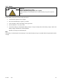
Heavy Equipment
WARNING
Unbalanced weight.
Improper lifting can cause severe injury or death and equipment damage.
Do not use lifting eyes. Lift the generator set using lifting bars inserted through the lifting
holes on the skid.
Hot Parts
WARNING
Hot coolant and steam.
Can cause severe injury or death.
Before removing the pressure cap, stop the generator set and allow it to cool. Then loosen
the pressure cap to relieve pressure. Fill system before starting unit.

12 TP-6694 9/20
WARNING
Hot engine and exhaust system.
Can cause severe injury or death.
Do not work on the generator set until it cools.
Servicing the alternator. Hot parts can cause severe injury or death. Avoid touching the alternator field or exciter armature.
When shorted, the alternator field and exciter armature become hot enough to cause severe burns.
Servicing the exhaust system. Hot parts can cause severe injury or death. Do not touch hot engine parts. The engine and
exhaust system components become extremely hot during operation.
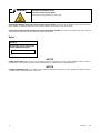
Notice
NOTICE
This generator set has been rewired
from its nameplate voltage to:
246242
NOTICE
Voltage reconnection. Affix a notice to the generator set after reconnecting the set to a voltage different from the voltage on
the nameplate. Order voltage reconnection decal 246242 from an authorized service distributor/dealer.
NOTICE
Canadian installations only. For standby service connect the output of the generator set to a suitably rated transfer switch in
accordance with Canadian Electrical Code, Part 1.

TP-6694 9/20 13
Introduction
This manual provides operation instructions for 10 kW and larger generator sets equipped with the following controllers:
APM402 generator set controller
Decision-Maker
®
3000 generator set controller
Note:
In 2018, Kohler adopted a global controller naming convention. To support this, the name of the Decision-Maker
®
3000 controller
has transitioned to APM402. The APM402 has the same form, fit and function as the Decision-Maker
®
3000 and supports the
same accessories.
Wiring diagram manuals are available separately. Refer to the engine operation manual for generator set engine scheduled
maintenance information.
Information in this publication represents data available at the time of print. Kohler Co. reserves the right to change this
publication and the products represented without notice and without any obligation or liability whatsoever.
Read this manual and carefully follow all procedures and safety precautions to ensure proper equipment operation and to avoid
bodily injury. Read and follow the Safety Precautions and Instructions section at the beginning of this manual. Keep this manual
with the equipment for future reference.
The equipment service requirements are very important to safe and efficient operation. Inspect the parts often and perform
required service at the prescribed intervals. Maintenance work must be performed by appropriately skilled and suitably trained
maintenance personnel familiar with generator set operation and service.
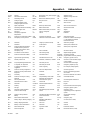
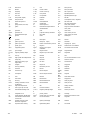
Abbreviations
This publication makes use of numerous abbreviations. Typically, the word(s) are spelled out along with the abbreviation in
parentheses when shown for the first time in a section. Appendix A: Abbreviations, also includes many abbreviation definitions.
SiteTech™ Software
Several instances in this manual refer to SiteTech™ software, which can be used for programming the APM402 or
Decision-Maker
®
3000 controller. SiteTech™ software is required for updating the controller application code (firmware), loading
personality profiles, and saving or loading controller configuration files. Contact your local distributor/dealer for assistance.
Note:
The APM402 controller uses different firmware than the Decision-Maker
®
3000 controller. Do not attempt to load
Decision-Maker
®
3000 firmware on an APM402 controller, or vice-versa.
To determine the generator set controller software version, go to the Overview menu.

14 TP-6694 9/20
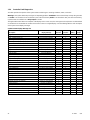
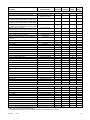
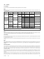
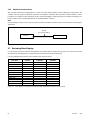
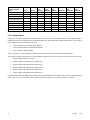
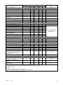
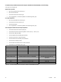
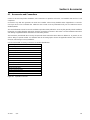
List of Related Materials
Separate literature contains communication and software information not provided in this manual. Figure 1 lists the available
literature part numbers.
Literature Description
Literature Part No.
APM402 Controller Spec Sheet
G6-161
Decision-Maker
®
3000 Controller Spec Sheet
G6-100
Generator Set/Controller Wiring Diagram Manual
Multiple Part Numbers Contact
your Distributor/Dealer
Modbus
®
Communications Protocol Operation Manual
TP-6113
SiteTech™ Software Operation Manual
TP-6701
Remote Serial Annunciator (RSA III)
TT-1625
Remote Serial Annunciator (RSA II)
TT-1485
Converters, Connections, and Controller Setup for Network Communication
TT-1405
Figure 1 Related Literature
Several engine manufacturers provide engines with electronic controls. These electronic controls indicate engine fault codes in
addition to the generator set controller. The engine operation and service literature provide information for identifying engine
fault codes. For the latest literature part numbers, see the respective Parts Catalog.

TP-6694 9/20 15
Service Assistance
For professional advice and conscientious service, please
contact your nearest Kohler distributor or dealer.
Visit the Kohler Co. website at KOHLERPower.com.
Look at the labels and decals on your Kohler product
or review the appropriate literature or documents
included with the product.
Call toll free in the US and Canada 1-800-544-2444.
Outside the US and Canada, call the nearest
regional office.
Headquarters Europe, Middle East, Africa (EMEA)
Kohler EMEA Headquarters
Netherlands B.V.
Kristallaan 1
4761 ZC Zevenbergen
The Netherlands
Phone: (31) 168 331630
Fax: (31) 168 331631
Asia Pacific
Kohler Asia Pacific Headquarters
Singapore, Republic of Singapore
Phone: (65) 6264-6422
Fax: (65) 6264-6455
China
North China Regional Office, Beijing
Phone: (86) 10 6518 7950
(86) 10 6518 7951
(86) 10 6518 7952
Fax: (86) 10 6518 7955
East China Regional Office, Shanghai
Phone: (86) 21 6288 0500
Fax: (86) 21 6288 0550
India, Bangladesh, Sri Lanka
India Regional Office
Bangalore, India
Phone: (91) 80 3366208
(91) 80 3366231
Fax: (91) 80 3315972
Japan, Korea
North Asia Regional Office
Tokyo, Japan
Phone: (813) 3440-4515
Fax: (813) 3440-2727

16 TP-6694 9/20

TP-6694 9/20 17
Section 1. Specifications and Features
1.1 Introduction
The spec sheets for each generator set provide model-specific generator and engine information. The controller spec sheet
provides specifications for this controller. Refer to the respective spec sheet for data not supplied in this manual. Refer to the
generator set service manual, installation manual, engine operation manual, and engine service manual for additional
specifications.
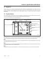
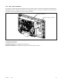
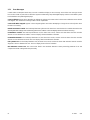
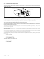
1.2 Controller Features
The controller features include the annunciator lamp, digital display and pushbutton/rotary selector dial, switches and controls,
and fuses and terminal strip. The following paragraphs detail the features by general topics.
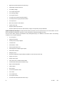
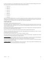
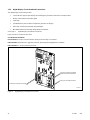
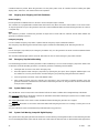
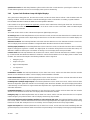
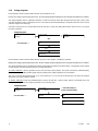
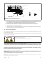
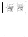
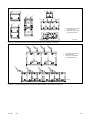
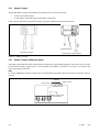
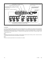
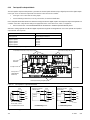
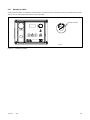
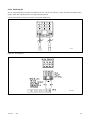
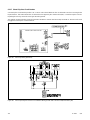
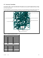
See Figure 2 for an illustration of the controller front panel.
Figure 2 Controller with Digital Display and Pushbutton/Rotary Selector Dial
The controller features, accessories, and menu displays depend upon the engine electronic control module (ECM) setup and
features. Controller features apply to generator set models with ECM and non-ECM engines unless otherwise noted.
Note:
Press the pushbutton/rotary selector dial to turn on the controller lights and display. The lights and display turn off 60 minutes
after the last entry when in the AUTO mode.
Note:
After about 5 minutes of no user input (pushbutton/rotary selector dial or buttons), the menu is reset to the top of the main menus
and auto-paging activates for the Overview submenus.
Note:
Measurements display in metric or English units. Use the Generator Set System menu to change the measurement display.
FAULT
ALARM SILENCERUNAUTOOFF/RESET
Emergency stop switch
Generator set master control switches,
OFF/RESET- AUTO-RUN buttons with lamps
Digital display
Alarm horn (behind panel)
Pushbutton/rotary selector dial
Annunciator fault lamp
Controller terminal strips (on
circuit board)
Alarm silence/lamp test button
with lamp
Mini USB connection
GM65741-

18 TP-6694 9/20
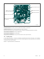
1.2.1 Switches and Controls
Note:
US/Metric Display is selectable in the Generator Set System Menu. See the section titled: Digital Display-Generator Set System
Menu.
Alarm Horn. The alarm horn alerts the operator or other attendants that a shutdown or warning condition exists.
Alarm (Horn) Silence. The alarm silence/lamp test switch silences the alarm horn at the operator’s discretion. Press the master
control switch AUTO button before pressing the alarm silence/lamp test button. The alarm horn cannot be silenced unless the
master control switch AUTO button is pressed.
Note:
Additional alarm silencing options are shown in the section titled: Digital Display-Generator Set System Menu.
Restore alarm horn switches at all locations including those on remote annunciator kits after correcting the fault shutdown to
avoid reactivating the alarm horn. See the section titled: Controller Resetting for resetting the controller.
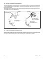
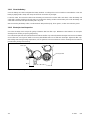
Emergency Stop. The operator-activated pushbutton immediately shuts down the generator set in emergency situations. Reset
the emergency stop switch after shutdown by pulling the emergency stop switch outward. Use the emergency stop switch for
emergency shutdowns only. Use the master control switch OFF/RESET button for normal shutdowns.
Generator Set Master Control Switches (OFF/RESET-AUTO-RUN). These switches reset the controller fault lamps and
start/stops the generator set. Additional information in shown in the section titled: Operation.
Lamp Test. Press and hold the Alarm Silence/Lamp Test button for two seconds to test the controller indicator lamps, alarm
horn, and digital display.
Manual Speed Adjust (Engine RPM). The control allows varying the engine speed for applications using closed transition ATS.
The user can set the nominal running frequency slightly above or below the utility frequency to ensure that synchronization
occurs. Additional information is shown in the section titled: GenSet System. Available as a factory-installed option or requires
a new factory personality profile.
Pushbutton/Rotary Selector Dial. This control provides access to the menus for monitoring. Press the selector dial to activate
the digital display and to select choices shown on the display. Rotate the dial to navigate through the menus.
The pushbutton/rotary selector dial has several features and functions:
Momentarily press the dial to activate the digital display if dark.
Rotate the dial to navigate through the main menus—turn clockwise to go forward (down) and counterclockwise to go
back (up). The menus do not wrap to the beginning.
Press the dial at a given main menu to access the submenus within the selected main menu.
When in the submenu, rotate the dial to navigate through the submenu—clockwise to go forward (down) and
counterclockwise to go back (up). The menus do not wrap to the beginning.
Momentarily press the dial when in the submenu to make a user selection choice (if available) or to go back to the
respective main menu.
Press the dial for at least 3 seconds to return to the top of the main menus (Overview) regardless if you are in the main
menus or submenus.
After about 5 minutes of no user input (pushbutton/ rotary selector dial or buttons), the menu resets to the top of the
main menus and auto-paging activates for the Overview submenus.

TP-6694 9/20 19
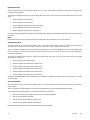
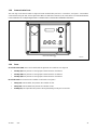
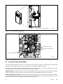
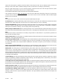
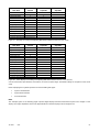
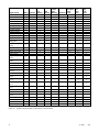
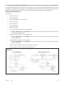
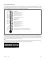
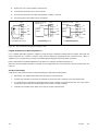
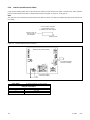
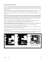
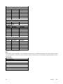
1.2.2 Annunciator Lamps
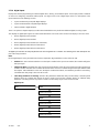
The controller has a single annunciator fault lamp providing visual generator set status. In addition, each button has a
corresponding lamp. See Figure 3.
Lamp/Button
Lamp color
Alarm (Fault) Lamp
Yellow (Warning) or Red (Shutdown)
Off/Reset Button
Red
Auto Button
Green (System Ready)
Run Button
Yellow
Alarm Silence/Lamp Test Button
Yellow
Figure 3 Annunciator Lamps
System Status Lamps (Master Control Switches)
The green lamp illuminates on the master control switch AUTO (automatic start) button indicating the system senses no faults
and the unit is ready to start by remote command.
The red lamp illuminates on the master control switch OFF/RESET button indicating the generator set is stopped.
The yellow lamp illuminates on the master control switch RUN button indicating the generator set is cranking or running from a
local command.
Only one of the three master control switch lamps will illuminate at any given time.
Alarm Silence Lamp. Yellow lamp illuminates indicating the alarm horn was silenced.
(System) Fault Lamp. Yellow lamp illuminates indicating a warning condition or red lamp illuminates indicating a shutdown
condition. See System Warning Fault Lamp and System Shutdown Fault Lamp following for system fault conditions.
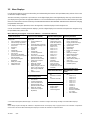
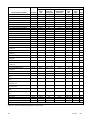
System Warning Fault Lamp. Yellow lamp identifies an existing fault condition that does not shut down the generator set. A
continuing system warning fault condition may cause a system shutdown. Correct all system warnings as soon as practical.
See the section titled: System Fault Warning Lamp with Digital Displays, for definitions of the items listed. The following
conditions cause a system warning:
AC sensing loss
Auxiliary input (analog or digital)
Battery charger communication loss
Battery charger fault
†
*
Note:
Optional input sensors not required with charger GM87448.
Battery charger identity conflict
Battery charger parameter mismatch
Battery fault
Common warning
Critical high fuel level (diesel-powered models only) *
Default parameters loaded
ECM diagnostics (multiple engine inputs)
Fuel tank leak (diesel-powered models only) *
Ground fault *
High battery voltage
High coolant temperature

20 TP-6694 9/20
High fuel level (diesel-powered models only) *
Input/output communication loss
Low battery voltage
Low coolant temperature
Low cranking voltage
Low engine oil level *
Low fuel (level for diesel-powered models) *
Low fuel (pressure for gas-powered models) *
Low oil pressure
Not-in-auto (master control switch)
Speed sensor fault
* Requires optional input sensors
†
Requires optional input sensors with all battery chargers except battery charger GM87448.
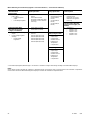
System Shutdown Fault Lamp. Red lamp indicates that the generator set has shut down because of a fault condition. The unit
will not start without resetting the controller, see the section titled: Controller Resetting procedure.
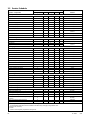
See the section titled: System Fault Shutdown Lamp with Digital Displays, for definitions of the items listed. The following
conditions cause a system shutdown:
AC sensing loss
Alternator protection
Auxiliary input (analog or digital)
Common fault
ECM address conflict
ECM communications loss
ECM diagnostics (multiple engine inputs)
ECM model mismatch
Emergency stop
Enclosure temperature: high shutdown (available on select Telecom units only)
Engine over speed
Engine under speed
File system error (controller firmware fault)
Fuel tank leak (diesel-powered models only)*
High coolant temperature
Internal failure
kW overload
Locked rotor (failed to crank)
Loss of fuel
Low coolant level*
Low engine oil level*
Low fuel level (diesel-powered models only) *
Page is loading ...
Page is loading ...
Page is loading ...
Page is loading ...
Page is loading ...
Page is loading ...
Page is loading ...
Page is loading ...
Page is loading ...
Page is loading ...
Page is loading ...
Page is loading ...
Page is loading ...
Page is loading ...
Page is loading ...
Page is loading ...
Page is loading ...
Page is loading ...
Page is loading ...
Page is loading ...
Page is loading ...
Page is loading ...
Page is loading ...
Page is loading ...
Page is loading ...
Page is loading ...
Page is loading ...
Page is loading ...
Page is loading ...
Page is loading ...
Page is loading ...
Page is loading ...
Page is loading ...
Page is loading ...
Page is loading ...
Page is loading ...
Page is loading ...
Page is loading ...
Page is loading ...
Page is loading ...
Page is loading ...
Page is loading ...
Page is loading ...
Page is loading ...
Page is loading ...
Page is loading ...
Page is loading ...
Page is loading ...
Page is loading ...
Page is loading ...
Page is loading ...
Page is loading ...
Page is loading ...
Page is loading ...
Page is loading ...
Page is loading ...
Page is loading ...
Page is loading ...
Page is loading ...
Page is loading ...
Page is loading ...
Page is loading ...
Page is loading ...
Page is loading ...
Page is loading ...
Page is loading ...
Page is loading ...
Page is loading ...
Page is loading ...
Page is loading ...
Page is loading ...
Page is loading ...
Page is loading ...
Page is loading ...
Page is loading ...
Page is loading ...
Page is loading ...
Page is loading ...
Page is loading ...
Page is loading ...
Page is loading ...
Page is loading ...
Page is loading ...
Page is loading ...
Page is loading ...
Page is loading ...
Page is loading ...
Page is loading ...
Page is loading ...
Page is loading ...
Page is loading ...
Page is loading ...
Page is loading ...
Page is loading ...
Page is loading ...
Page is loading ...
Page is loading ...
Page is loading ...
Page is loading ...
Page is loading ...
Page is loading ...
Page is loading ...
Page is loading ...
Page is loading ...
Page is loading ...
Page is loading ...
Page is loading ...
Page is loading ...
Page is loading ...
Page is loading ...
Page is loading ...
Page is loading ...
Page is loading ...
Page is loading ...
Page is loading ...
Page is loading ...
Page is loading ...
Page is loading ...
Page is loading ...
Page is loading ...
Page is loading ...
Page is loading ...
Page is loading ...
Page is loading ...
Page is loading ...
Page is loading ...
Page is loading ...
Page is loading ...
Page is loading ...
Page is loading ...
Page is loading ...
Page is loading ...
Page is loading ...
Page is loading ...
Page is loading ...
Page is loading ...
Page is loading ...
Page is loading ...
Page is loading ...
Page is loading ...
Page is loading ...
Page is loading ...
Page is loading ...
Page is loading ...
Page is loading ...
Page is loading ...
Page is loading ...
Page is loading ...
Page is loading ...
Page is loading ...
Page is loading ...
Page is loading ...
-
 1
1
-
 2
2
-
 3
3
-
 4
4
-
 5
5
-
 6
6
-
 7
7
-
 8
8
-
 9
9
-
 10
10
-
 11
11
-
 12
12
-
 13
13
-
 14
14
-
 15
15
-
 16
16
-
 17
17
-
 18
18
-
 19
19
-
 20
20
-
 21
21
-
 22
22
-
 23
23
-
 24
24
-
 25
25
-
 26
26
-
 27
27
-
 28
28
-
 29
29
-
 30
30
-
 31
31
-
 32
32
-
 33
33
-
 34
34
-
 35
35
-
 36
36
-
 37
37
-
 38
38
-
 39
39
-
 40
40
-
 41
41
-
 42
42
-
 43
43
-
 44
44
-
 45
45
-
 46
46
-
 47
47
-
 48
48
-
 49
49
-
 50
50
-
 51
51
-
 52
52
-
 53
53
-
 54
54
-
 55
55
-
 56
56
-
 57
57
-
 58
58
-
 59
59
-
 60
60
-
 61
61
-
 62
62
-
 63
63
-
 64
64
-
 65
65
-
 66
66
-
 67
67
-
 68
68
-
 69
69
-
 70
70
-
 71
71
-
 72
72
-
 73
73
-
 74
74
-
 75
75
-
 76
76
-
 77
77
-
 78
78
-
 79
79
-
 80
80
-
 81
81
-
 82
82
-
 83
83
-
 84
84
-
 85
85
-
 86
86
-
 87
87
-
 88
88
-
 89
89
-
 90
90
-
 91
91
-
 92
92
-
 93
93
-
 94
94
-
 95
95
-
 96
96
-
 97
97
-
 98
98
-
 99
99
-
 100
100
-
 101
101
-
 102
102
-
 103
103
-
 104
104
-
 105
105
-
 106
106
-
 107
107
-
 108
108
-
 109
109
-
 110
110
-
 111
111
-
 112
112
-
 113
113
-
 114
114
-
 115
115
-
 116
116
-
 117
117
-
 118
118
-
 119
119
-
 120
120
-
 121
121
-
 122
122
-
 123
123
-
 124
124
-
 125
125
-
 126
126
-
 127
127
-
 128
128
-
 129
129
-
 130
130
-
 131
131
-
 132
132
-
 133
133
-
 134
134
-
 135
135
-
 136
136
-
 137
137
-
 138
138
-
 139
139
-
 140
140
-
 141
141
-
 142
142
-
 143
143
-
 144
144
-
 145
145
-
 146
146
-
 147
147
-
 148
148
-
 149
149
-
 150
150
-
 151
151
-
 152
152
-
 153
153
-
 154
154
-
 155
155
-
 156
156
-
 157
157
-
 158
158
-
 159
159
-
 160
160
-
 161
161
-
 162
162
-
 163
163
-
 164
164
-
 165
165
-
 166
166
-
 167
167
-
 168
168
-
 169
169
-
 170
170
-
 171
171
-
 172
172


Kohler 100REZGD Operating instructions
- Category
- Power generators
- Type
- Operating instructions
Ask a question and I''ll find the answer in the document
Finding information in a document is now easier with AI
Related papers
-
Kohler 600REOZVB Operating instructions
-
Kohler 500REOZJC Operating instructions
-
Kohler 500REZK Operating instructions
-
-
Kohler KD1350 Operating instructions
-
Kohler 48VDC User manual
-
-
-
-
Other documents
-
WarmlyYours SCA-DUAL Controller Product information
-
Onan MDKBU User manual
-
C.E. Niehoff & Co N1224 Troubleshooting guide
-
Emax EGS070PT User guide
-
BLACK DECKER BDV1085 Owner's manual
-
Garnet 709-4LP User guide
-
-
Smartgen HSC941 Owner's manual
-
 Champion Power Equipment 100895 Installation guide
-
Garnet 709-BTP3 User guide
