SkyTraq NS-HP-GN2 User manual

Type
User manual

SkyTraq NS-HP-GN2 is a high-performance multi-band multi-GNSS RTK receiver that enables precise positioning with centimeter-level accuracy. It supports GPS/QZSS L1/L2C, BeiDou B1I/B2I, Galileo E1/E5b, and GLONASS L1/L2 RTK, making it suitable for various applications such as GIS data collection, precision farming, unmanned aerial vehicle guidance, and race car performance measurement. With its 100mA power consumption at 3.3V, the NS-HP-GN2 is energy-efficient and can be easily integrated into various systems.

SkyTraq NS-HP-GN2 is a high-performance multi-band multi-GNSS RTK receiver that enables precise positioning with centimeter-level accuracy. It supports GPS/QZSS L1/L2C, BeiDou B1I/B2I, Galileo E1/E5b, and GLONASS L1/L2 RTK, making it suitable for various applications such as GIS data collection, precision farming, unmanned aerial vehicle guidance, and race car performance measurement. With its 100mA power consumption at 3.3V, the NS-HP-GN2 is energy-efficient and can be easily integrated into various systems.

1
NS-HP-GN2 Users Guide
Rev. 0.4
August 21, 2020
2
Table of Contents
1. INTRODUCTION .................................................................................................... 3
2. FEATURES OF NS-HP-GN2 ..................................................................................... 5
3. APPLICATIONS ....................................................................................................... 6
4. PIN OUT DESCRIPTION .......................................................................................... 7
5. CHECK OUT BASIC GPS FUNCTIONALITY .............................................................. 9
6. SET UP NS-HP-GN2 AS RTK BASE ........................................................................ 13
Known Base Antenna Position ............................................................................. 14
Unknown Base Antenna Position ......................................................................... 15
Base Stream Format ............................................................................................. 17
7. USE NS-HP-GN2 AS RTK ROVER .......................................................................... 20
8. MOVING BASE MODE ......................................................................................... 26
9. ADVANCED MOVING BASE MODE ...................................................................... 28
10. ACTIVE ANTENNA CONSIDERATION ................................................................... 29
11. FIRMWARE UPDATE ............................................................................................ 30
12. POSSIBLE CONNECTION FOR QUADCOPTER APPLICATION ................................ 32
CHANGE LOG ................................................................................................................ 34
3
1. INTRODUCTION
NS-HP-GN2 is a high performance multi-band multi-GNSS RTK receiver. It can accept RTCM 3.x
message or SkyTraq carrier phase raw measurement data from a base station to perform carrier phase
RTK processing, achieving centimeter-level accuracy relative positioning.
When used with RTCM base station, the supported RTCM message types are:
Type 1004 Extended L1/L2 GPS RTK observables
Type 1005 Stationary RTK Reference Station ARP
Type 1012 Extended L1/L2 GLONASS RTK observables
Type 1033 Receiver and antenna description
Type 1074 GPS MSM4
Type 1075 GPS MSM5
Type 1076 GPS MSM6
Type 1077 GPS MSM7
Type 1084 GLONASS MSM4
Type 1085 GLONASS MSM5
Type 1086 GLONASS MSM6
Type 1087 GLONASS MSM7
Type 1094 Galileo MSM4
Type 1095 Galileo MSM5
Type 1096 Galileo MSM6
Type 1097 Galileo MSM7
Type 1114 QZSS MSM4
Type 1115 QZSS MSM5
Type 1116 QZSS MSM6
Type 1117 QZSS MSM7
Type 1124 BeiDou MSM4
Type 1125 BeiDou MSM5
Type 1126 BeiDou MSM6
Type 1127 BeiDou MSM7
Type 1230 GLONASS Code Phase Biases
4
For centimeter-level RTK accuracy, NS-HP-GN2 requires much better operating condition than
conventional meter-level accuracy GPS receiver:
* Under open sky without interference
* Signal level over 37dB/Hz
* 8 or more satellites above 15 degree elevation angle with good satellite geometry
If above condition is not met, NS-HP-GN2 will not get centimeter-level accuracy RTK solution.
Without base station data input, NS-HP-GN2 works like a normal GNSS receiver.
When used with a RTCM 3.x Virtual Reference Station (VRS) RTK base, one rover NS-HP-GN2 is needed.
If one wishes to setup a local base station to work with rover, then two NS-HP-GN2 will be needed,
one for base and another for rover.
Default NMEA output baud rate is 115200.
Rover expects RTCM 3.x or SkyTraq raw measurement data at input baud rate of 115200
5
2. FEATURES OF NS-HP-GN2
RTK Receiver Features
* Support RTK base and rover modes
* Supports GPS/QZSS L1/L2C + Beidou B1I/B2I + Galileo E1/E5b + GLONASS L1/L2 RTK
* RTK position accuracy: 1cm + 1ppm
* RTK initialization time: < 10sec
* 100mA @ 3.3V
6
3. APPLICATIONS
NS-HP-GN2 may be used for:
1. GIS data collection
2. Precision farming machine guidance
3. Precision grass cutting machine guidance
4. Precision guidance of unmanned aerial vehicles
5. Precise position tracking of race cars for performance measurement
7
4. PIN OUT DESCRIPTION
Pin No.
Name
Description
J1
1
BOOT_SEL
No connection for normal use. Pull-low for loading firmware into empty or
corrupted Flash memory from ROM mode for the master processor.
2
NC
No connection, empty pin
3
1PPS
One-pulse-per-second (1PPS) time mark output, 3.3V LVTTL. The rising edge
synchronized to UTC second when getting 3D position fix. The pulse duration is
about 100msec at rate of 1 Hz.
4
TRIG
External trigger input for generating STI,005 time stamp, 3.3V LV-TTL
5
NC
No connection, empty pin
6
RX2
UART serial data input, 3.3V LVTTL.
One simplex asynchronous serial UART port is implemented. This UART input is
used for receiving RTCM-SC104 data or SkyTraq raw measurement data from
the base at 115200.
7
NC
No connection, empty pin
8
RSTN
External active-low reset input to the receiver.
Only needed when power supply rise time is very slow or software controlled
reset is desired.
9
NC
No connection, empty pin
10
GND
Ground
11
NC
No connection, empty pin
8
12
GND
Ground
Pin No.
Name
Description
J2
1
GND
Ground
2
NC
No connection, empty pin
3
NC
No connection, empty pin
4
NC
No connection, empty pin
5
NC
No connection, empty pin
6
NC
No connection, empty pin
7
NC
No connection, empty pin
8
TXD
UART serial data output, 3.3V LVTTL.
One full-duplex asynchronous serial UART port is implemented. This UART
output is used for sending position, time and velocity information from the
receiver in NMEA-0183 format. When idle, this pin output HIGH.
9
RXD
UART serial data input, 3.3V LVTTL.
One full-duplex asynchronous serial UART port is implemented. This UART input
is for sending commands or information to the receiver in SkyTraq binary
protocol. In the idle condition, this pin should be driven HIGH.
10
V_BCKP
Backup supply voltage for internal RTC and backup SRAM, 1.3V ~ 3.6V. V_BCKP
must be applied whenever VCC is applied. This pin should be powered
continuously to minimize the startup time. If VCC and V_BCKP are both
removed, the receiver will be in factory default mode upon power up, all user
configuration set is lost. For applications the does not care cold starting every
time, this pin can be connect to VCC.
11
VCC
Power supply, 3.3V DC
12
GND
Ground
9
5. CHECK OUT BASIC GPS FUNCTIONALITY
Hook up as below, connect to an UART-to-USB bridge breakout board, connect antenna to RF_IN, and
place antenna at a location having clear sky view. After driver for the UART-to-USB bridge chip has
been installed, select proper COM port and 115200 baud rate on GNSS Viewer, click CLOSE, GNSS
Viewer will show signal being acquired and tracked.
10
GNSS Viewer for Windows PC can be downloaded from:
http://navspark.mybigcommerce.com/content/GNSS_Viewer.zip
http://navspark.mybigcommerce.com/content/GNSS-Viewer-User-Guide.rev0.2.pdf
If uncertain of the COM port, it can be found from the Windows Device Manager.
11
If wishing to change NMEA output baud rate, from Binary pull-down menu select Configure Serial Port,
select desired baud rate and Update to SRAM+Flash.
12
If wishing to change NMEA solution output updated rate, from Binary pull-down menu select
Configure Position Update Rate, select desired update rate and Update to SRAM+Flash.
When changing to higher update rate, make sure baud rate in use can accommodate it. If baud rate is
not fast enough, NMEA message output will be truncated.
13
6. SET UP NS-HP-GN2 AS RTK BASE
Hook up as below; connect to an UART-to-USB bridge breakout board for connecting to GNSS
Viewer running on a Windows PC.
14
Known Base Antenna Position
When configured as base, NS-HP-GN2 will output its position along with carrier phase raw
measurement data over UART TXD. If base NS-HP-GN2 antenna will be placed at a location with
known position, the position information can be set into NS-HP-GN2 using GNSS Viewer.
From RTK pull-down menu, select Configure RTK Mode And Operational Function, select RTK base
mode, select Static Mode and enter antenna latitude/longitude in degrees and ellipsoidal height in
meter, update to SRAM+Flash.
15
Unknown Base Antenna Position
If base antenna position is unknown, set to let it survey for 60sec upon power up. From GNSS Viewer
RTK pull-down menu, select Configure RTK Mode And Operational Function, select Survey Mode and
set Survey Length to 60 and Update to SRAM+Flash.
16
When later in use, after base NS-HP-GN2 gets position fix and self-surveyed for 60 seconds, it enters
into static mode. On GNSS Viewer scatter plot view, one will see the blue dot stop drifting around
after static mode is entered; Set Origin button may need to be clicked to center the view in order to
see the scatter plot. Next time powering on the base NS-HP-GN2, it will still start from survey mode
again, self-survey for 60 seconds, with self-surveyed antenna location at different location unless static
mode is chosen and a constant position is entered. To see what the self-surveyed latitude, longitude,
and altitude values are, from GNSS Viewer RTK pull-down menu, select Query RTK Mode And
Operational Function.
To use the base at some fixed location, use these steps to self-survey and retrieve surveyed antenna
position, then set the antenna position into the base NS-HP-GN2 so that it’ll have the same entered
position every time its powered on later. No need to set the antenna position into base NS-HP-GN2 if
only testing and becoming acquainted with it.
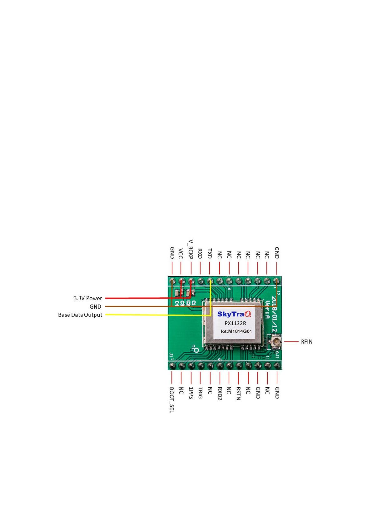
Once base NS-HP-GN2 has been properly configured, later usage require only connecting an RTK
antenna, apply power, and send TXD base output data to the rover NS-HP-GN2.
17
Base Stream Format
After configuring NS-HP-GN2 to RTK base mode, the default base stream outputs are packaged in
SkyTraq RAW measurement protocol. The outputted messages include:
1) Message type 0xDE SV and Channel Status
2) Message type 0xDF Receiver Navigation Status
3) Message type 0xE0 GPS Subframe Data
4) Message type 0xE1 GLONASS String Data
5) Message type 0xE2 Beidou D1 Subframe Data
6) Message type 0xE3 Beidou D2 Subframe Data
7) Message type 0xE5 Extended RAW Measurement
8) Message type 0xE6 General Subframe Data
9) Message type 0xE7 GNSS SV and Channel Status
10) Message type 0xE8 GNSS SV Elevation and Azimuth Status
The necessary message types of base stream used for NS-HP-GN2 RTK rover mode are only Receiver
Navigation Status (0xDF) and Extended RAW Measurement (0xE5). To decrease the throughput of
base stream, other unnecessary message types can be disabled from the base stream. From GNSS
Viewer RAW pull-down menu, select Configure Binary Measurement Data Out, disable unnecessary
message types, select necessary message types and Update to SRAM+FLASH.
18
In addition to SkyTraq RAW measurement protocol, NS-HP-GN2 also supports RTCM 3 format output.
From GNSS viewer RAW pull-down menu, select Configure RTCM Measurement Data Out, select
Enable RTCM Output, select Stationary RTK Reference Station ARP , select MSM7s and Update to
SRAM+FLASH.
19
Its deserved to be mentioned that it’s necessary to restart rover receiver if the format of base stream
is changed.
RTCM format has much less data rate requirement than binary raw measurement format. For
applications that send base data over radio to the rover, RTCM format is preferred. A minimum of
19200bps data rate is required for quad-GNSS operation; can be reduced to 9600 if using only two
GNSS constellations.
20
7. USE NS-HP-GN2 AS RTK ROVER
NS-HP-GN2 is configured as rover during production. If NS-HP-GN2 has been previously configured as
base, to re-configure it as rover, hook up as below; connect to an UART-to-USB bridge breakout board
for connecting to GNSS Viewer running on a Windows PC.
From GNSS Viewer RTK pull down menu, select Configure RTK Mode and Operational Function, select
RTK rover mode, Normal RTK Operational Function and update to SRAM+Flash
  • Page 1 1
  • Page 2 2
  • Page 3 3
  • Page 4 4
  • Page 5 5
  • Page 6 6
  • Page 7 7
  • Page 8 8
  • Page 9 9
  • Page 10 10
  • Page 11 11
  • Page 12 12
  • Page 13 13
  • Page 14 14
  • Page 15 15
  • Page 16 16
  • Page 17 17
  • Page 18 18
  • Page 19 19
  • Page 20 20
  • Page 21 21
  • Page 22 22
  • Page 23 23
  • Page 24 24
  • Page 25 25
  • Page 26 26
  • Page 27 27
  • Page 28 28
  • Page 29 29
  • Page 30 30
  • Page 31 31
  • Page 32 32
  • Page 33 33
  • Page 34 34

SkyTraq NS-HP-GN2 User manual

Type
User manual

SkyTraq NS-HP-GN2 is a high-performance multi-band multi-GNSS RTK receiver that enables precise positioning with centimeter-level accuracy. It supports GPS/QZSS L1/L2C, BeiDou B1I/B2I, Galileo E1/E5b, and GLONASS L1/L2 RTK, making it suitable for various applications such as GIS data collection, precision farming, unmanned aerial vehicle guidance, and race car performance measurement. With its 100mA power consumption at 3.3V, the NS-HP-GN2 is energy-efficient and can be easily integrated into various systems.

Ask a question and I''ll find the answer in the document

Finding information in a document is now easier with AI