Page is loading ...

User Guide
Ultrastar® Data102
Regulatory Model: H4102-J
December 2019
Rev. 1.14
1ET1094

User Guide Table of Contents
Table of Contents
Revision History..........................................................................................................................................................................v
Copyright................................................................................................................................................................................. viii
Points of Contact...................................................................................................................................................................... ix
Product Label Information.................................................................................................................................................ix
Chapter 1. Overview........................................................................................................................................................................ 1
® Data102 Description..............................................................................................................................................................2
System Architecture Overview.................................................................................................................................................2
System Level Block Diagram.....................................................................................................................................................3
Ultrastar Data102 Specification Summary................................................................................................................................ 3
Ultrastar Data102 Layout........................................................................................................................................................... 5
List of Customer Replaceable Units (CRUs)............................................................................................................................ 7
LEDs............................................................................................................................................................................................ 8
Front and Rear IO LEDs..................................................................................................................................................... 8
IOM LEDs........................................................................................................................................................................... 10
IOM Fan LED...................................................................................................................................................................... 10
PSU LED.............................................................................................................................................................................. 11
Rear Fan LED..................................................................................................................................................................... 12
Drive Assembly LED..........................................................................................................................................................13
Ultrastar Data102 Rack Requirements..................................................................................................................................... 14
Compatible Rack Hardware Configuration..................................................................................................................... 15
Power Requirements................................................................................................................................................................ 17
ESD.............................................................................................................................................................................................18
Enclosure Cooling.................................................................................................................................................................... 18
Host Connectivity.....................................................................................................................................................................18
Supported SKUs.......................................................................................................................................................................20
List of Compatible Drives....................................................................................................................................................... 20
Chapter 2. System Management Overview............................................................................................................................... 35
Firmware Features Overview.................................................................................................................................................36
Supported Operating Systems............................................................................................................................................... 37
OOBM Management Overview............................................................................................................................................... 37
SCSI Enclosure Services Page 02...........................................................................................................................................37
Chapter 3. Component Overviews..............................................................................................................................................39
Chassis Description................................................................................................................................................................. 40
i

User Guide Table of Contents
Chassis Specifications......................................................................................................................................................40
Chassis Layout.................................................................................................................................................................. 40
IOM Description....................................................................................................................................................................... 42
IOM Specifications............................................................................................................................................................42
IOM Layout........................................................................................................................................................................ 43
IOM Blank Description......................................................................................................................................................43
PSU Description....................................................................................................................................................................... 44
PSU Specifications............................................................................................................................................................ 44
PSU Layout........................................................................................................................................................................ 45
Rear Fan Description............................................................................................................................................................... 46
Rear Fan Specifications.................................................................................................................................................... 46
Rear Fan Layout................................................................................................................................................................ 46
IOM Fan Description................................................................................................................................................................ 47
IOM Fan Specifications.....................................................................................................................................................48
IOM Fan Layout.................................................................................................................................................................48
Rails Description...................................................................................................................................................................... 49
Rails Specifications...........................................................................................................................................................50
Rails Layout.......................................................................................................................................................................50
Rear Cover Alignment Bracket Description.................................................................................................................... 51
CMA Description......................................................................................................................................................................52
CMA Specifications...........................................................................................................................................................53
CMA Layout.......................................................................................................................................................................53
CMA Cable Tray................................................................................................................................................................54
CMA Lite Description.............................................................................................................................................................. 55
CMA Lite Specifications................................................................................................................................................... 56
CMA Lite Layout............................................................................................................................................................... 56
Drive Assembly Description....................................................................................................................................................57
Drive Assembly Specifications........................................................................................................................................ 58
Drive Assembly Layout.................................................................................................................................................... 58
2.5" Drive Carrier Description......................................................................................................................................... 59
Drive Blank Description....................................................................................................................................................62
Chapter 4. Part Replacement...................................................................................................................................................... 64
Part Replacement Service Window....................................................................................................................................... 65
IOM Replacement.................................................................................................................................................................... 65
PSU Replacement.................................................................................................................................................................... 68
ii

User Guide Table of Contents
Rear Fan Replacement............................................................................................................................................................. 71
IOM Fan Replacement..............................................................................................................................................................74
Drive Assembly Replacement................................................................................................................................................. 75
CMA Replacement...................................................................................................................................................................80
Rails Replacement.................................................................................................................................................................. 103
Chassis Replacement............................................................................................................................................................. 135
Special Considerations for Cable Routing............................................................................................................................174
Cabling for CMA Standard and CMA Lite.............................................................................................................................176
Before You Begin............................................................................................................................................................ 176
Cabling CMA Standard................................................................................................................................................... 177
Cable Configuration for CMA Lite................................................................................................................................. 178
Chapter 5. System Management............................................................................................................................................... 180
Firmware Upgrade.................................................................................................................................................................. 181
Downloading Firmware from the Support Portal..........................................................................................................181
Linux Upgrade Preparation.............................................................................................................................................183
Linux Upgrade to New Firmware.................................................................................................................................. 185
Non-Automatic Firmware Activation in Linux................................................................................................................187
Windows Upgrade Preparation.....................................................................................................................................188
Windows Upgrade to New Firmware...........................................................................................................................190
Non-Automatic Firmware Activation in Windows........................................................................................................ 193
Upgrading Firmware with OOBM.................................................................................................................................. 196
Configuring OOBM Network Settings...................................................................................................................................197
Configuring OOBM Network Settings Using SES......................................................................................................... 197
Zoning......................................................................................................................................................................................199
Before Zoning.................................................................................................................................................................200
Predefined Zoning Configurations................................................................................................................................200
sg_senddiag Command.................................................................................................................................................205
Enabling Zoning using Linux......................................................................................................................................... 206
Disabling Zoning using Linux......................................................................................................................................... 210
Enabling Zoning using Windows...................................................................................................................................213
Disabling Zoning using Windows................................................................................................................................. 216
Subenclosure Nickname........................................................................................................................................................220
Setting the Subenclosure Nickname............................................................................................................................ 220
Partially Populated Enclosures..............................................................................................................................................222
Partial Population Configurations.................................................................................................................................. 222
iii

User Guide Table of Contents
Installing Drives...............................................................................................................................................................225
Daisy Chaining........................................................................................................................................................................228
Daisy Chaining Configurations...................................................................................................................................... 228
One Host Cable Configurations....................................................................................................................................229
Two Host Cable Configurations....................................................................................................................................235
Cabling for Daisy Chaining............................................................................................................................................240
Chapter 6. Safety.........................................................................................................................................................................247
Electrostatic Discharge......................................................................................................................................................... 248
Optimizing Location.............................................................................................................................................................. 248
Power Connections............................................................................................................................................................... 248
Power Cords.......................................................................................................................................................................... 248
Rackmountable Systems........................................................................................................................................................249
Safety and Service.................................................................................................................................................................249
Safety Warnings and Cautions............................................................................................................................................. 250
Chapter 7. Disclaimers.................................................................................................................................................................251
Restricted Access Location.................................................................................................................................................. 252
Safety Compliance.................................................................................................................................................................252
Electromagnetic Compatibility (EMC) Class A Compliance...............................................................................................252
Country Certifications............................................................................................................................................................253
Chapter 8. Regulatory Statements...........................................................................................................................................254
Europe (CE Declaration of Conformity)............................................................................................................................... 255
FCC Class A Notice...............................................................................................................................................................255
ICES-003 Class A Notice—Avis NMB-003, Classe A...........................................................................................................255
Japanese Compliance Statement, Class A ITE....................................................................................................................255
Taiwan Warning Label Statement, Class A ITE................................................................................................................... 255
iv

User Guide Revision History
Revision History
Date Revision Comment
November 2017 Revision 1.0 Initial Release
November 2017 Revision 1.1
• The crossbar on the CMA was changed. See CMA Description
(page 52).
• Removed Lowline power specs from Power Requirements
(page 17).
• Changed required rack depth, see Required Rack Depth (page
5).
• Changed typical power consumption, see Typical Power
Consumption (page 4).
• Updated LED Flash Patterns, see LEDs (page 8).
December 2017 Revision 1.2
• Added active cable support
• Added firmware upgrade section. See Firmware Upgrade
(page 181).
• Updated the Non-Op altitude specification. See Non-
Operational Altitude (page 4).
January 2018 Revision 1.21 Updated the product name
January 2018 Revision 1.3
• Updated information on the 2.5" drive carrier option. See 2.5"
Drive Carrier Description (page 59).
• Added torque requirements for all screws used in the
enclosure.
• Updated the IOM replacement section to account for the
possibility of a firmware mismatch. See IOM Replacement
(page 65).
• Updated the drive assembly installation instructions to clarify
the orientation of the drive assemblies. Drive Assembly
Replacement (page 75).
April 2018 Revision 1.4
• Updated Compatible Drives List. See List of Compatible Drives
(page 20).
• Updated the Rack Requirements. See Ultrastar Data102 Rack
Requirements (page 14).
• Updated the Firmware Upgrades. See: Firmware Upgrade
(page 181)
May 2018 Revision 1.5 Added the Part Replacement Service Window. See: Part
Replacement Service Window (page 65)
June 2018 Revision 1.6
• Updated Compatible Drives List. See List of Compatible Drives
(page 20)
v

User Guide Revision History
Date Revision Comment
• Updated the Firmware Upgrade section. See Firmware
Upgrade (page 181)
• Updated the Firmware Download section. See Downloading
Firmware from the Support Portal (page 181)
• Updated the System Architecture Overview section. See
System Architecture Overview (page 2)
• Updated the Daisy Chaining section. See Daisy Chaining (page
228)
• Added the Rear Cover Alignment Bracket Description. See
Rear Cover Alignment Bracket Description (page 51)
November 2018 Revision 1.7
• Updated the images in the Daisy Chaining section. See Daisy
Chaining (page 228)
• Updated List of CRUs. See List of Customer Replaceable Units
(CRUs) (page 7)
• Updated Compatible Drives List. See List of Compatible Drives
(page 20)
• Updated the Host Connectivity section. See: Host Connectivity
(page 18)
May 2019 Revision 1.8
• Changed senddiag commands from images to codeblocks.
See sg_senddiag Command (page 205).
• Updated daisy-chaining tables to match diagrams. See Two
Host Cable Configurations (page 235).
• Corrected OOBM zoning configuration instructions. See
Predefined Zoning Configurations (page 200).
• Added Configuring OOBM Network Settings (page 197).
May 2019 Revision 1.9
• Corrected explanation of SATA configuration in Firmware
Upgrade (page 181) section.
June 2019 Revision 1.10
• Updated the Host Connectivity section. See: Host Connectivity
(page 18)
• Added Windows syntax examples and reorganized the
Upgrading Firmware with OOBM (page 196) section
June 2019 Revision 1.11 Updated the Host Connectivity section. See: Host Connectivity
(page 18)
July 2019 Revision 1.12
Moved the following topics to the Overview (page 1) section:
• Ultrastar Data102 Rack Requirements (page 14)
• Power Requirements (page 17)
• ESD (page 18)
• Enclosure Cooling (page 18)
• Host Connectivity (page 18)
vi

User Guide Revision History
Date Revision Comment
Moved the Supported Operating Systems (page 37) topic to the
System Management Overview (page 35) section.
Corrected LED identification tables for IOMs, PSUs, and drives in
the LEDs (page 8) section.
Updated servicing image to correct length values and rail servicing
extension in Ultrastar Data102 Rack Requirements (page 14)
section.
Updated the following for CMA Lite:
• Added CMA Lite Component Overview (page 55) section,
including description, specs, and layout.
• Updated CMA Replacement (page 80) section to combine
CMA Standard and CMA Lite content where applicable.
• Updated Maximum HD Mini-SAS Configuration (page 178)
section.
Added a note about OOBM ports configured for DHCP by default
to the OOBM Management Overview (page 37) section.
November 2019 Revision 1.13
• Replaced references to He12 drives with Ultrastrar DC HC520
in List of Compatible Drives (page 20)
• Changed device references from OS-specific (/dev/sgX for
Linux and SCSIX:X,X,X for Windows) to generic (<dev>)
throughout.
• Updated table for Approved SAS Cables in Host Connectivity
(page 18)
• Added Subenclosure Nickname (page 220) section
• Updated Supported Operating Systems (page 37)
• Updated images of captive chassis-cover screws throughout
• Updated the Daisy Chaining configurations in Daisy Chaining
(page 228)
December 2019 1.14
• Rebranded document to WD design
• Updated the List of Compatible Drives (page 20)
vii

User Guide Copyright
Copyright
The following paragraph does not apply to the United Kingdom or any country where such provisions
are inconsistent with local law: Western Digital PROVIDES THIS PUBLICATION "AS IS" WITHOUT
WARRANTY OF ANY KIND, EITHER EXPRESS OR IMPLIED, INCLUDING, BUT NOT LIMITED TO, THE IMPLIED
WARRANTIES OF MERCHANTABILITY OR FITNESS FOR A PARTICULAR PURPOSE. Some states do not allow
disclaimer or express or implied warranties in certain transactions, therefore, this statement may not
apply to you.
This publication could include technical inaccuracies or typographical errors. Changes are periodically made
to the information herein; these changes will be incorporated in new editions of the publication. Western
Digital may make improvements or changes in any products or programs described in this publication at any
time.
It is possible that this publication may contain reference to, or information about, Western Digital products
(machines and programs), programming, or services that are not announced in your country. Such references
or information must not be construed to mean that Western Digital intends to announce such Western Digital
products, programming, or services in your country.
Technical information about this product is available by contacting your local Western Digital representative
or on the Internet at: support@wdc.com
Western Digital may have patents or pending patent applications covering subject matter in this document.
The furnishing of this document does not give you any license to these patents.
Copyright © 2017-2019 Western Digital Corporation or its affiliates.
Western Digital
5601 Great Oaks Parkway
San Jose, CA 95119
Long Live Data™ is a trademark of Western Digital, Inc. and its affiliates in the United States and/or other
countries.
Western Digital trademarks are authorized for use in countries and jurisdictions in which Western Digital
has the right to use, market and advertise the brands. Other product names are trademarks or registered
trademarks of their respective owners.
Other product names are trademarks or registered trademarks of their respective owners.
One MB is equal to one million bytes, one GB is equal to one billion bytes, one TB equals 1,000GB (one trillion
bytes) and one PB equals 1,000TB when referring to storage capacity. Usable capacity will vary from the raw
capacity due to object storage methodologies and other factors.
References in this publication to Western Digital products, programs or services do not imply that Western
Digital intends to make these available in all countries in which Western Digital operates.
Product information is provided for information purposes only and does not constitute a warranty.
Information is true as of the date of publication and is subject to change. Actual results may vary. This
publication is for general guidance only. Photographs may show design models.
viii

User Guide Points of Contact
Points of Contact
For further assistance with a Western Digital product, contact Western Digital Datacenter Platforms technical
support. Please be prepared to provide the following information: part number (P/N), serial number (S/N),
product name and/or model number, and a brief description of the issue.
Email:
support@wdc.com
Website:
https://portal.wdc.com/Support/s/
1.1
Product Label Information
The following product information is required for technical support requests:
• Part Number (P/N)
• Serial Number (S/N)
• Product Name and/or Model Number (MODEL)
This information may be found on the product label, which is affixed to an exterior, non-removable surface of
the chassis. The following is an example label with the applicable information fields highlighted:
ix

Western Digital
Overview
This section provides a high level overview of the features of the
Ultrastar Data102.
In This Chapter:
- Ultrastar Data102 Description....................... 2
- System Architecture Overview..................... 2
- System Level Block Diagram.........................3
- Ultrastar Data102 Specification
Summary........................................................... 3
- Ultrastar Data102 Layout............................... 5
- List of Customer Replaceable Units
(CRUs)................................................................7
- LEDs................................................................. 8
- Ultrastar Data102 Rack Requirements........ 14
- Power Requirements.....................................17
- ESD................................................................. 18
1

User Guide
1. Overview
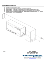
1.1 Ultrastar ® Data102 Description
1.1
Ultrastar® Data102 Description
Figure 2: Ultrastar Data102
The Ultrastar® Data102 is a 4U form factor, high availability, high density, rack-mounted storage enclosure
that is capable of hosting up to 102 SAS or SATA drives. The maximum data storage capacity of the Ultrastar
Data102 is 1.428 PB using 14TB Ultrastar® HC530 drives . (For a full list of compatible drives and total
storage capacities, see the hg (page 20).) The enclosure runs on an input voltage of 200 - 240 VAC and
consumes ~1300W of power under typical conditions. It requires a maximum of ~1600W at full load.
It is designed to fit within a 4U rack space and requires 1181-1197 mm (46.5in. - 47.13in.) of usable rack space,
frame to frame. A fully loaded system will add 118.8 kg / 262 lbs. of static load when fully loaded with drives.
• 4U Storage Enclosure
• Supports up to 102 Drives
• Can support 3.5” drives and 2.5” SSD drives (2.5" requires an adapter) in the 102 available drive bays.
• Up to 12W per drive slot for the 102 data storage drives (Cannot exceed 85A on the 5V rail)
• House and control four (4) N+1 redundant 80mm rear fans
• House and control a dual rotor 40mm internal IOM Fan
• Controlled by two (2) redundant I/O Modules
*
• Powered by two (2) redundant 1600W PSUs
• Full high availability with independent dual paths to all HDDs
• Toolless replacement of all Customer Replaceable Units (CRUs)
• Fits within a standard EIA-310 rack including all necessary cable management (see: Compatible Rack
Hardware Configuration (page 15))
• Supports up to 3m passive SAS cables (limited to 3m or less) or active cables (any length)
• Supports High line (220-240 VAC) Input Power
1.2
System Architecture Overview
* SATA based models will only include 1 IOM
2

User Guide
1. Overview
1.3 System Level Block Diagram
The Ultrastar Data102 IOM uses a cascaded expander design to allow for connection to all 102 drives. A
48-port primary expander connects with the six host ports, has a x3 link to the other IOM for IOM-IOM
communication and syncing, and also has a x10 SAS link to each secondary expander. Each secondary
expander then connects with fifty-one (51) drives.
The out-of-band management microprocessor provides an Ethernet connection using a Redfish/RESTful
API to access the various enclosure services. All the SES enclosure information can be obtained through the
out-of-band management port. Major use cases for this feature include obtaining storage subsystem health
information, locating enclosure components using the IDENT LEDs, and updating firmware.
The system FPGAs control and report the states of the system fans, enclosure LEDs, connector LEDs, drive
LEDs, and T10 drive power disable signals on the 102 data storage drives.
Note: To use T10 power disable, the drives installed must also support this feature.
The I
2
C architecture is designed to support only one single master on any given bus. The primary expander
will be the master on each I
2
C bus. There are eight I
2
C buses used in the Ultrastar Data102 enclosure.
The number of devices on each bus are balanced to allow communication to peripheral devices and not
overload any one bus. The devices connected on the I
2
C buses include the enclosure VPDs, temp sensors,
baseboard FPGAs, and SAS connectors among others.
1.3
System Level Block Diagram
The following image shows the system block diagram for the Ultrastar Data102.
Figure 3: System Block Diagram
3

User Guide
1. Overview
1.4 Ultrastar Data102 Specification Summary
1.4
Ultrastar Data102 Specification Summary
Table 1: Environmental Specification
Specification Non-Operational Operational
Temperature -40°C to 70°C 5°C to 35°C
Temperature Gradient 30°C per hour max 20°C per hour max
Temperature De-rating 1°C per 300m above 3000m 1°C per 300m above 900m
Relative Humidity 8-90% Non-Condensing 8-90% Non-Condensing
Relative Humidity Gradient 30% per hour maximum 30% per hour maximum
Altitude -300m to 12,000m /
-984 ft. to 39,370 ft
-300m to 3048m /
-984 ft. to 10,000 ft.
Table 2: Electrical Specifications
Specification Value
Max Power Consumption ~1600W
Typical Power Consumption
*
~1300W
Input Voltage 200 - 240 VAC
PSU Connector Type C14
Inrush Current Maximum (per
PSU)
AC line inrush current shall not exceed 40A peak, for up to
one-quarter of the AC cycle after which, the input current
should be no more than the specified maximum input current.
PSU Efficiency 80 PLUS Platinum
Caution: The Ultrastar Data102 can only be plugged into highline. If the unit is plugged into
lowline, the PSU will report a "Critical" state when status pages are queried using SES. In this
case, the enclosure will power up, but the drives will not. The enclosure will remain in low-
power mode.
Table 3: Mechanical Specifications
Specification Non-Operational Operational
Shock 10G, 0 - peak,11ms half sine;
3 positive and 3 negative
pulses in each axis Shock
5G, 0 - peak, 11ms half sine; 3 positive
and 3 negative pulses in each axis-
minimum 6 seconds between shocks
to allow for write/read recovery
Vibration 0.75G, 0 - peak swept sine;
5 -500Hz; 1 complete sweep
@ 1/2 octave per minute
0.10G,0 - peak swept sine; 5
-500Hz; 1 complete sweep
@ 1/2octave per minute
* Max and typical power consumption values represent the output power to the system. Input power will vary depending
on the PSU efficiency and load sharing between PSUs.
4

User Guide
1. Overview
1.5 Ultrastar Data102 Layout
Specification Non-Operational Operational
Weight 118.8 kg / 262 lbs.
Enclosure Dimensions W: 447mm x L: 1048.5 mm x H: 175mm / W: 17.6in. x L: 41.28in. x H: 6.89in.
CMA Standard: 1183mm / 46.57in.Length of Enclosure w/
CMA
CMA Lite: 1148mm / 45.19in.
Required Rack Width 450mm with (17.72in.) with 465mm (18.31in.) ± 1.5mm
nominal hole spacing. See EIA-310 Rack Standard
Required Rack Depth 1181-1197 mm (46.5in. - 47.13in.) of usable rack space, frame to frame
Rack Units (U) 4U
Vertical Rack Rail
Spacing
812.8mm - 914.4mm / 32 in. - 36 in.
Table 4: Performance Specifications
Specification Value
Number of Drive Slots 102
Data Transfer Rates 12GBps SAS / 6Gbps SATA
Max Raw Data Storage Capacity 1.428 PB using 14TB Ultrastar® HC530 drives
SAS Ports 12 x Mini-SAS HD (6 per IOM)
2 x 10/100/1G Ethernet
1.5
Ultrastar Data102 Layout
5

User Guide
1. Overview
1.5 Ultrastar Data102 Layout
Figure 4: Front and Rear Product Layout
Table 5: Front and Rear Component Identification
Number Component
1 Enclosure Handles
2 CMAs
3 CMA Tray
4 Rear Fans
5 PSUs
6 Chassis Cover
7 Rear Cover Alignment Brackets
8 Rails
The following is an image of the layout of the major system components inside the Ultrastar Data102.
6

User Guide
1. Overview
1.6 List of Customer Replaceable Units (CRUs)
Figure 5: Component Layout
1.6
List of Customer Replaceable Units (CRUs)
The following table lists the replaceable components and their part numbers.
Table 6: List of Replaceable Components
Component Part Number
Ultrastar Data102 Chassis with a single IOM and PSU 1EX0440
Ultrastar Data102 Chassis with IOMs and PSUs 1EX0441
IOM 1EX0430
IOM Blank 1EX0431
PSU 1600W 1EX0434
Rear Fan 1EX0433
IOM Fan 1EX0432
Rails (CMA Standard) 1EX0435
Rails (CMA Lite) 1EX1601
Rear Cover Alignment Bracket 1EX2288
CMA Standard Arms 1EX0437
CMA Lite Kit (w/ rails, spacer brackets, and CMA) 1EX1825
CMA Lite Arm 1EX1834
7

User Guide
1. Overview
1.7 LEDs
Component Part Number
CMA Lite Cable Tray 1EX1603
CMA Cable Tray 1EX1119
3.5 in. Drive Carrier, Qty=1 1EX0438
3.5 in. to 2.5 in. conversion Drive Carrier, Qty=1 1EX0439
3.5 in. Drive Blank, Qty=1 1EX0429
Power Cable for PDU, C13-C14, 18AWG, 3m, Qty=1 1EX1158
HD Mini-SAS to HD Mini-SAS, 3m, Qty=2 1EX1533
1.7
LEDs
1.7.1
Front and Rear IO LEDs
The Ultrastar Data102 has a number of LEDs on the exterior of the enclosure that display various system
statuses. There are three on the front and three on the rear that mirror each other and provide general
status. This allows the status of the enclosure to be visible from either side of the rack.
Figure 6: Front LEDs
From the rear there are the three enclosure status LEDs and LEDs on the Ethernet and SAS ports.
Table 7: Front LED Identification
Number LED Name Color Behavior
1 Identify Blue
Blink @ 1 Hz (50% duty cycle) – Blinks only
when Identification has been activated. Will
blink when any component is identified.
2 Fault Amber Blink @ 1 Hz (50% duty cycle) – Enclosure has a fault
8

User Guide
1. Overview
1.7 LEDs
Number LED Name Color Behavior
Off – Enclosure has no fault
Note: LEDs have a 50% duty cycle (On
for 2 seconds, off for less than a second).
3 Power Green Solid - Powered On
Figure 7: Rear IO LEDs
Table 8: Rear LED Identification
Number LED Name Color Behavior
1 SAS Link Status Green
Solid – SAS Cable Connected
Off – SAS Cable Not Connected
2
SAS Fault
Status
Amber
Blink @ 1 Hz (50% duty cycle) – SAS connection fault
Off – No SAS connection fault
Note: LEDs have a 50% duty cycle (On
for 2 seconds, off for less than a second).
3 Identification Blue
Blink @ 1 Hz (50% duty cycle) – Blinks only
when Identification has been activated. Will
blink when any component is identified.
4 Fault Amber
Blink @ 1 Hz (50% duty cycle) – Enclosure has a fault
Off – Enclosure has no fault
9

User Guide
1. Overview
1.7 LEDs
Number LED Name Color Behavior
Note: LEDs have a 50% duty cycle (On
for 2 seconds, off for less than a second).
5 Power Green Solid - Powered On
6
Ethernet
Connectors
Link/Activity
Green/
Amber
Off - Operating at 10 Mbps
Green Solid - Operating at 100 Mbps
Amber Solid - Operating at 1Gpbs
7
Ethernet
Connector
Speed
Green
Off - No Connection
Solid - Connected
Blink - Activity
1.7.2
IOM LEDs
The IOM has three LEDs, one each for power, fault, and identification.
Figure 8: IOM LEDs
Table 9: IOM LED Identification
LED Name Color Behavior
IOM Identification Blue
Blink @ 0.5 Hz (75% duty cycle) – Blinks only
when IOM Identification has been activated.
Off - Not being identified
IOM Fault Amber
Blink @ 0.5 Hz (75% duty cycle) – IOM has Fault
Off - IOM is functioning normally
IOM Power Green
Solid - IOM is on
Off - IOM is off
1.7.3
IOM Fan LED
The IOM Fan has a single LED that has three distinct states, one each for a fault condition, identification,
and power off.
10
/