Western Digital OpenFlex Composable Infrastructure Installation guide
- Type
- Installation guide

Installation
Guide
OpenFlex F3100 and E3000
1ET2047
Version 1.0
October 2019

Installation Guide Points of Contact
Points of Contact
For further assistance with a Western Digital product, contact Wester Digital Datacenter Platforms technical
support. Please be prepared to provide the following information: part number (P/N), serial number (S/N),
product name and/or model number, and a brief description of the issue.
Email:
support@wdc.com
Website:
https://portal.wdc.com/Support/s/
i

Installation Guide Table of Contents
Table of Contents
Points of Contact....................................................................................................................................i
Chapter 1. Installation......................................................................................................1
Installation Equipment Requirements................................................................................................. 2
Installation Safety................................................................................................................................. 2
Before You Begin................................................................................................................................. 3
DHCP..............................................................................................................................................4
How to Report Damage.............................................................................................................. 4
Installation Procedure.......................................................................................................................... 6
Accessing Storage............................................................................................................................. 23
Chapter 2. Safety............................................................................................................31
Electrostatic Discharge......................................................................................................................32
Optimizing Location...........................................................................................................................32
Power Connections............................................................................................................................32
Power Cords.......................................................................................................................................32
Rackmountable Systems....................................................................................................................33
Restricted Access Location...............................................................................................................33
Safety and Service............................................................................................................................. 33
Safety Warnings and Cautions..........................................................................................................34
ii


Installation Guide
1. Installation
1.1 Installation Equipment Requirements
1.1
Installation Equipment Requirements
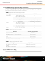
This section lists everything that must be in place or available to perform the installation. This includes the
equipment and components that are included in the packaging.
Table 1: Equipment and Components Included
Category Item # Included
E3000 Chassis w/ PSUs,
Fans, and BMC Pre-installed
1
Rack-mounting Rails
w/ mounting hardware
1 set of 2
F3100 1 - 10 depending on configuration
Components
Device Blanks 0 - 9 depending on configuration
M5 x 12mm T15 Torx Pan
Head screws w/ washers
6Screws
M5 x 10mm T15 Torx Flat
Head screws w/ washers
6
Cables 3m, C14 - C15 Power Cables 2
Table 2: Additional Equipment Needed
Equipment Required or Recommended?
T15 Torx Screwdriver Required
T15 Torx Screwdriver w/ Torque Measuring
Capability
Recommended
Level Recommended
Lift Equipment Recommended
ESD Mitigation Equipment (site specific) Required
Table 3: Torque Specifications for Screws
Screw Type Torque Value
M5 x 12mm T15 Torx screws w/
washers
3.38-3.61 Nm / 30-32 in-lbf
M5 x 10mm T15 Torx screws 3.38-3.61 Nm / 30-32 in-lbf
1.2
Installation Safety
2

Installation Guide
1. Installation
1.3 Before You Begin
Safety is the number one priority for personnel responsible for installing the OpenFlex F3100 and E3000
platform. This section outlines what to consider before performing an installation.
Protect Yourself and Others
Before any installation of an OpenFlex F3100 and E3000 it is important to take steps to keep all personnel
performing the installation (or individuals near the installation site safe). Make sure all paths and floors are
clean and free of obstacles. Do not wear clothing that is loose or can become tangled or catch on anything,
or clothing that is too tight and may restrict movement. Read all safety labels and instructions in this manual
and on the equipment being used for installation. Never lift the E3000 alone. It should always be teamlifted.
When installing the unit in a rack, it is highly recommended that you install it at the lowest possible U height
of the rack. This is intended to prevent an imbalanced load and it keeps the center of gravity low on the rack
to help prevent tipping hazards.
Protect Your Equipment
Always use the proper tooling outlined in this document during installation. This includes torque
specifications and driver heads when installing screws, lifting equipment, and safety equipment, as well
as the E3000 and F3100s themselves. Always respect the ESD requirements outlined at your site. Use
ESD mitigation and prevention equipment to prevent discharges that may damage equipment. During
installation, do not tip the enclosure.
The following is a list of safety equipment that should be considered before proceeding:
• Safety Shoes/Steel-toed Boots (ESD Safe is a plus)
• Lifting equipment
• ESD mitigation equipment
• Safety vests and hard hats
• Rack support or anchoring equipment
Warning: Never lift the chassis by the handles on the rear fan modules! They are not intended
to support the weight of the unit. Injury or damage to the unit is likely.
1.3
Before You Begin
3

Installation Guide
1. Installation
1.3 Before You Begin
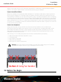
The installation process for the OpenFlex F3100 and E3000 happens in four basic phases: Unpacking,
Chassis Installation, Device Installation, and Initial Bringup. The following procedure outlines the steps for
Chassis and Device Installation in a rack.
1.3.1
DHCP
When the E3000 BMC module is powered on, it will try to establish an IP address using DHCP. The E3000
and F3100 require access to a DHCP Server to access the OCGUI. Access to a DHCP server should be
setup ahead of time to ensure the installation of the product is not gated. If a DHCP server is not present
on the network that the E3000 is connected to, access to the BMC and the OCGUI will not be available.
1.3.2
How to Report Damage
During the installation process, there are a number of inspection steps where the installation team should
be looking for damage to the product that may have occurred during shipment. If damage is found,
document the items using the following process.
Step 1 :
Take two digital photos of the damaged packaging or component, one closeup shot showing
the damage in detail and one further out so the support engineers working the case can see
where the damage occurred.
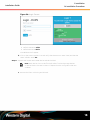
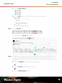
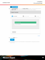
Step 2 : Open a web browser and go to https://portal.wdc.com/Support/s/login/.
The Western Digital Enterprise Support Center page will appear:
Step 3 : Log in to your Support Portal account using an email address and password:
4

Installation Guide
1. Installation
1.3 Before You Begin
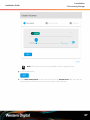
The Western Digital Enterprise Support Center page will appear, providing various support-
related options:
Step 4 : Click the Cases icon:
The Case Detail page will appear:
5

Installation Guide
1. Installation
1.4 Installation Procedure
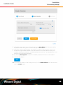
Step 5 :
At a minimum, select a Case Reason, Brand, and Severity from the available drop-down menus,
and provide a brief explanation of the issue in the Summary field; these fields are required.
Step 6 : In addition, type the Part Number and Serial Number into the appropriate fields, and select the
Product Category and Product Sub-Category that match your Product Name / Model Number.
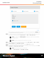
Tip: For instructions on filling out the remaining fields, refer to the Enterprise
Support Center User Guide, available through a the link on the Enterprise
Support Center page:
Step 7 : Click the Submit button:
1.4
Installation Procedure
6

Installation Guide
1. Installation
1.4 Installation Procedure
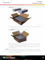
Step 1 : Remove the plastic retention bands with a box cutter and remove the top cap by lifting it off
and away from the pallet using the cutouts on the sides of the carton. This step may require two
people to finish.
Figure 6: Unband and Remove Top Cap
Step 2 :
Verify that the top tray contains all of the accessories. This should include all rails, screws,
washers, and cables. Reference the packaging contents list in Table 1: Equipment and
Components Included (page 2) for details.
Step 3 : Remove the rails from the rail kit box.
a. Remove the rail kit box from the Accessory Tray located directly under the packaging cap.
b. Open the rail kit box and remove the top protective materials.
c.
Lift the rails out of the box and inspect them for damage.
7

Installation Guide
1. Installation
1.4 Installation Procedure
Figure 7: Removing the Rails
Step 4 : Install the rails into the rack that will receive the E3000.
Tip: A T15 Torx screwdriver with torque measuring capabilities is recommended for
this step.
Caution: It is important to always install rackmounted equipment in the lowest
available U height in order to ensure the safest installation possible. This keeps the
center of gravity on the rack low and reduces the risk of tipping.
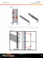
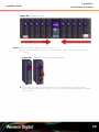
a.
Determine which of the rails is the right and which is the left. From the front of the rack,
the rails will need to be installed into the right and left sides. The front of the rail can be
identified by the single rack mount pin and the rear of the rail can be identified by the two
rack mount pins as shown in the following image. Another way to orient the rails correctly
is to make sure that the shelf-flanges that support the enclosure are facing the inside of the
rack where the enclosure will reside.
8

Installation Guide
1. Installation
1.4 Installation Procedure
Figure 8: Rails Identification
b.
Determine that the planned installation location of the enclosure has a full 3 rack units (U)
worth of space. A 3U of space is about 5.25 in./133.33 mm from bottom to top as shown in
the following image.
Figure 9: Enclosure Installation Space
9

Installation Guide
1. Installation
1.4 Installation Procedure
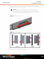
c. From the front of the rack, insert the front pin into the front vertical rack rail and slide the
spring loaded rail until the rear pins line up with the rear vertical rack rail. Ensure that the rail
is installed in the bottom portion of the 3U space.
Attention: The rack-mounted rail system that comes with the E3000 uses a
spring tensioning mechanism that allows the rails to be soft-installed without
tools. However, the spring is only strong enough to hold the rails in place, and
all T15 Torx screws must be installed for safe mounting. Never install the E3000
in a set of rails that was not secured with these screws.
Figure 10: Rail Spring Compression
Figure 11: Rail Pin Installation
d.
From the rear of the rack use the T15 Torx screwdriver to install the two T15 screws into the
rail kits to secure the rail to the vertical rack rails.
10

Installation Guide
1. Installation
1.4 Installation Procedure
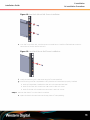
Figure 12: Rear Rack Mount Rail Screw Installation
e.
From the front of the rack, use the T15 Torx screwdriver to install the flat head T15 screws to
secure the rail to the vertical rack rails.
Figure 13: Front Rack Mount Rail Screw Installation
f. Install the remaining rail in the same way the first was Installed.
g.
The following must be completed to verify that the rails have been properly installed:
• Both rails have been installed into the rack unit space and are level
• Both of the front rails contain one T15 screw in each rail mount
• Both of the rear rails contain two T15 screw in each rail mount
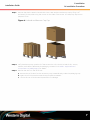
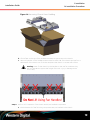
Step 5 : Remove the chassis from the chassis container.
a. Open the chassis box and remove the top piece of foam padding.
11

Installation Guide
1. Installation
1.4 Installation Procedure
Figure 14: Removing Chassis Foam Padding
b. Lift the flaps on the top of the cardboard endcaps to get access to the chassis.
c.
Have one member of the installation team stand on each side of the chassis and perform a
safe teamlift of the chassis out of the box and place the chassis on an ESD safe surface.
Warning: Never lift the chassis by the handles on the rear fan modules! They
are not intended to support the weight of the unit. Injury or damage to the
unit is likely.
Step 6 : Perform a full inspection of the chassis and all pre-installed components.
a. Check that the all of the following components are pre-installed in the chassis:
12

Installation Guide
1. Installation
1.4 Installation Procedure
• 2 x PSUs (Rear)
• 4 x System Fans (Rear)
• 1 x BMC Module (Front)
b. Perform a visual inspection for damage. Check all pre-installed components, the front device
slots, rack ears, and exterior surfaces for dents, scratches and contamination.
Step 7 : Install the Chassis into the rack.
Tip: A T15 Torx screwdriver is required for this step.
a.
Carefully slide the chassis onto the rails until the chassis mounts are flush with the mounts on
the rails.
Figure 16: Chassis Installation
b.
Use a T15 Torx screwdriver to install the three M5 screws that secure the chassis rack ears to
the vertical rack rail. Do this to both rack ears to fully secure the enclosure.
Figure 17: Chassis Screw Installation
c. Verify that the Chassis is secured to the rails and does not move when pulled. Remove the
screws and try again if the enclosure is not secured to the rack.
13

Installation Guide
1. Installation
1.4 Installation Procedure
d. Install the rack ear covers onto both of the chassis mounts.
Figure 18: Rack Ear Cover Installation
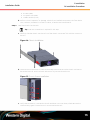
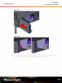
Step 8 : Find and record the mac address of the BMC Module
a. From the front of the rack, grasp the release handle with your forefinger on the bottom and
thumb on the top of the release latch and press the release latch with your thumb. The
handle will eject from the front of the BMC Module.
Figure 19: BMC Module Release Handle Operation
b.
Lower the release handle until the BMC module is fully unseated (this occurs at about 60°)
and pull the BMC module out of the chassis ensuring that you support the under side of the
BMC module with your other hand.
14

Installation Guide
1. Installation
1.4 Installation Procedure
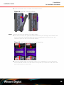
Figure 20: Uninstall BMC Module
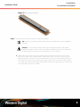
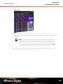
c.
Locate the sticker on the side of the BMC Module that lists the mac address for that module
and record it somewhere for later use. The mac address of the BMC module will be used to
later to navigate to the BMC GUI in order to access the storage.
Figure 21: BMC Module MAC Address Label
d.
Grasp the release handle with your forefinger on the bottom and thumb on the top of the
release latch and press the release latch with your thumb. The handle will eject from the
front of the BMC module.
15

Installation Guide
1. Installation
1.4 Installation Procedure
Figure 22: BMC Module Release Handle Operation
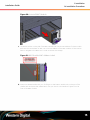
e.
Gently slide the BMC module into the center chassis slot until the release handle is engaged
with the chassis. When the handle lifts up slightly, it is an indicator that the release handle is
engaged with the chassis.
Figure 23: BMC Module Installation
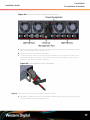
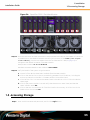
Step 9 : Power up the E3000.
16

Installation Guide
1. Installation
1.4 Installation Procedure
Figure 24: Enclosure Power and Data Connections
a. Connect the power cables into each of the PSUs at the rear of the unit. The BMC Module,
PSUs, and Fan Modules should all power on.
b. Verify the LEDs are illuminated on the PSUs.
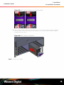
c.
Tighten the cable retention clips by sliding the retention clip forward on the PSUs until it
stops near the cable connectors. Doing this will ensure that the retention clips function
properly in the event the cable is pulled on.
Figure 25: Cable Retention Clip Operation
Step 10 : Verify the health of the power supplies using the OCGUI.
a. Navigate to the BMC Module using the address established in the previous step, and login
using the default username and password.
17
Page is loading ...
Page is loading ...
Page is loading ...
Page is loading ...
Page is loading ...
Page is loading ...
Page is loading ...
Page is loading ...
Page is loading ...
Page is loading ...
Page is loading ...
Page is loading ...
Page is loading ...
Page is loading ...
Page is loading ...
Page is loading ...
Page is loading ...
-
 1
1
-
 2
2
-
 3
3
-
 4
4
-
 5
5
-
 6
6
-
 7
7
-
 8
8
-
 9
9
-
 10
10
-
 11
11
-
 12
12
-
 13
13
-
 14
14
-
 15
15
-
 16
16
-
 17
17
-
 18
18
-
 19
19
-
 20
20
-
 21
21
-
 22
22
-
 23
23
-
 24
24
-
 25
25
-
 26
26
-
 27
27
-
 28
28
-
 29
29
-
 30
30
-
 31
31
-
 32
32
-
 33
33
-
 34
34
-
 35
35
-
 36
36
-
 37
37


Western Digital OpenFlex Composable Infrastructure Installation guide
- Type
- Installation guide
Ask a question and I''ll find the answer in the document
Finding information in a document is now easier with AI
Related papers
-
 Western Digital OpenFlex F3100 User manual
-
 Western Digital OpenFlex Composable Infrastructure Installation guide
-
Western Digital H4060-S Installation guide
-
 Western Digital Ultrastar Data60 Hybrid Storage Platform Installation guide
-
 Western Digital Ultrastar Data102 Hybrid Storage Platform Installation guide
-
 Western Digital Ultrastar Data102 Hybrid Storage Platform User guide
-
 Western Digital Ultrastar Data60 Hybrid Storage Platform User manual


Other documents
-
Gigabyte W291-Z00 Installation Instructions Manual
-
Analog way QuickMatrix 4K Operating instructions
-
Dell W-620 Installation guide
-
 Final Audio Design E3000 User manual
-
ICS T15 Digital temperature transmitter User manual
-
Nvidia DGX A100 User manual
-
 Regency Fireplace Products Classic F3100 Owner's manual
-
HP VA7110 User manual
-
Dell Latitude E7440 Owner's manual
-
 Regency Fireplace Products Classic F3100 Owner's manual


