Lithonia Lighting 4" Baffle LED Module Kit Installation guide
- Type
- Installation guide
Page is loading ...
Page is loading ...
Page is loading ...

Lithonia Lighting
Downlighting
One Lithonia Way / Conyers, GA 30012
800-315-4935 / www.lithonia.com
INSTALLATION INSTRUCTIONS
Part Number: >Version A<
©2007 Acuity Brands Lighting, Inc., 03/18/2014
Page 4 of 12
LK3, LK4, LK5 SERIES REMODEL FIXTURE, LK3 LED
120V ONLY LK4 LED, LK5 LED
SAVE THESE INSTRUCTIONS
Prior to installing the fixture, disconnect ALL power supplies to the
unit. This unit may be installed in IC or NON-IC rated installations.
For NON-IC applications, no insulation may be placed over the top
of/or within 3” (76mm) of fixture.
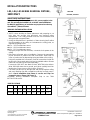
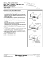
REMODEL FIXTURE INSTALLATION
1. NOTE: when deciding on fixture placement and preparing to cut
hole, take into account joist placement and electrical wiring
requirements. Your ceiling material must be non-combustible and
strong enough to support fixture.
2. Using the template that is provided, or fixture housing itself outline
the circle pattern on the ceiling to cut between the ceiling joists, as
required by lighting layout.
LK3= 3 1/8 inch diameter cutout.
LK4= 4 1/8 inch diameter cutout.
LK5= 5 1/2 inch diameter cutout.
3. Using the proper hole-saw and tools, cut out the circle pattern in the
ceiling.
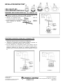
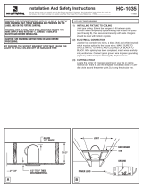
4. Disconnect all power prior to installation. Remove the appropriate
pry-out knockout on junction box with screw driver. Open snap on
cover on junction box by depressing spring and allow cover to hang.
Using the provided wire connecters, make all connections inside the
junction box. Bring supply wires into box by shielded cable or Romex
cable and connectors (Purchased separately).
Connect the 120V HOT wire black to black; NEUTRAL wire white to
white; GROUND bare wire to ground, push wires carefully back into
junction box. Close snap on cover in place. (Figure 1)
5. Tilt fixture junction box up through hole and hold up against ceiling
and push retaining clips with screwdriver until they securely snap in
place. Check installation that fixture is secure and clips are
snapped in place. (Figure 2 & Figure 3)
6.Remodel housing installation complete. Skip to the TRIM
INSTALATION section.
*SPECIFICATIONS
CICODE
*224V0T
*224V0V
*224V0W
*235JN6
*224V19
*224V0Y
*225Y49
*231YKG
MODEL #
LK3BMW
LED M4
LK4BMW
LED M4
LK5BMW
LED M4
LK4G2MW
LED M4
LK5GMW
LED M4
LK4BORB
LED M4
LK5BORB
LED M4
LK4BMW
LED MW WL
M6
SUITABLE
LOCATIONS
WET
Locations
WET
Locations
WET
Locations
DAMP
Locations
DAMP
Locations
WET
Locations
WET
Locations
WET
Locations
Figure 1
Figure 2

Lithonia Lighting
Downlighting
One Lithonia Way / Conyers, GA 30012
800-315-4935 / www.lithonia.com
INSTALLATION INSTRUCTIONS
Part Number: >Version A<
©2007 Acuity Brands Lighting, Inc., 03/18/2014
Page 5 of 12
LKA3, LKA4, LKA5 NEW CONSTRUCTION
ADAPTER (SOLD SEPARATELY)
LKABH HANGER BARS (SOLD SEPARATELY) LKA3
120V ONLY LKA4, LKA5
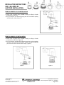
NEW CONSTRUCTION ADAPTER INSTALLATION
1. NOTE: when deciding on fixture placement take into account joist
placement and electrical wiring requirements. Your ceiling material
must be non-combustible.
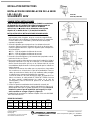
2. Install NEW CONSTRUCTION ADAPTER( purchased separately)
by positioning the LKABH BAR HANGERS (purchased separately)
between the ceiling joists and nailing in the attached nails to secure
in place. (Figure 4 & 5)
3. Disconnect all power prior to installation. Pull supply wire through
ADAPTER hole. Remove the appropriate pry-out knockout on
junction box with screw driver. Open snap on cover on junction box
by depressing spring and allow cover to hang.
Using the provided wire connecters, make all connections inside the
Junction box.
Bring supply wires into Junction box by shielded cable or Romex
cable and connectors (Purchased separately).
Connect the 120V HOT wire black to black; NEUTRAL wire white to
white; GROUND bare wire to ground, push wires carefully back into
junction box. Close snap on cover in place.
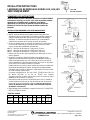
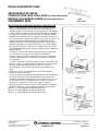
4. REMOVE the (3) SPRING CLIPS from the REMODEL FIXTURE
and discard.
5. Tilt Fixture junction box up through hole and position adapter spring
clips with alignment grooves and rectangular openings on
REMODEL CAN HOUSING. Push up for spring clips to securely
snap in and lock in place. (Figure 6)
6. After electrical inspection is approved, complete ceiling installation,
with the following cut out openings to
LKA3= 3 1/4 inch diameter cutout.
LKA4= 4 1/4 inch diameter cutout.
LKA5= 5 5/8 inch diameter cutout.
Figure 4
Figure 5
Figure 6

Lithonia Lighting
Downlighting
One Lithonia Way / Conyers, GA 30012
800-315-4935 / www.lithonia.com
INSTALLATION INSTRUCTIONS
Part Number: >Version A<
©2007 Acuity Brands Lighting, Inc., 03/18/2014
Page 6 of 12
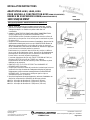
LK3, LK4, AND LK5
LED TRIM INSTALLATION
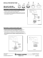
TRIM FOR MODELS LK3 LK4 INSTALLATION
1. Disconnect all power prior to installation.
2. Attach male connector from installed housing in ceiling to female
connector from LED trim.
3. Once connectors are attached, gently push trim into fixture opening
until flush with ceiling. (Figure 7)
TRIM FOR MODELS LK5 INSTALLATION
1. Disconnect all power prior to installation.
2. Attach male connector from installed housing in ceiling to female
connector from LED trim. (Figure 8)
3. Once connectors are attached, squeeze the torsion springs together
and place into brackets inside fixture. Release springs, and gently
push trim into fixture until flush with ceiling. (Figure 9)
Figure 7
Figure 9
Figure 8
Page is loading ...
Page is loading ...
Page is loading ...
Page is loading ...
Page is loading ...
Page is loading ...
-
 1
1
-
 2
2
-
 3
3
-
 4
4
-
 5
5
-
 6
6
-
 7
7
-
 8
8
-
 9
9
-
 10
10
-
 11
11
-
 12
12


Lithonia Lighting 4" Baffle LED Module Kit Installation guide
- Type
- Installation guide
Ask a question and I''ll find the answer in the document
Finding information in a document is now easier with AI
in other languages
Related papers
-
Lithonia Lighting LK5OAZ TRMW M6 Installation guide
-
Lithonia Lighting TZR 2 54T5HO MVOLT 1/4 GEB10PS Installation guide
-
-
-
Lithonia Lighting LP6N Wallwash Installation guide
-
-
Lithonia Lighting LDN635/20GZ10HSG Operating instructions
-
-
-
Lithonia Lighting RSXF2 LED Floodlight Installation guide
Other documents
-
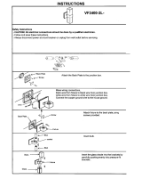 Designers Choice Collection VF3400-2L-CH Operating instructions
-
SEHNLICH REC-5CCT-6IN INCARLED 5CCT LED Recessed Lighting Installation guide
-
NICOR 14101AR Installation guide
-
-
Euri Lighting DLC4S-2000e Installation guide
-
 Acuity Brands Lighting KAX LED Installation guide
-
Euri Lighting DLC4SQ-2050e Installation guide
-
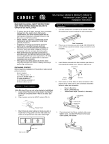 CANDEX M630215 Installation guide
-
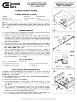 Commercial Electric CER6CP6743-4PK Installation guide
-
 Generation Lighting 1179 Operating instructions


