Page is loading ...

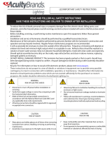
READ AND FOLLOW ALL SAFETY INSTRUCTIONS!
SAVE THESE INSTRUCTIONS AND DELIVER TO OWNER AFTER INSTALLATION
· To reduce the risk of death, personal injury or property damage from re, electric shock, falling parts, cuts/
abrasions, and other hazards please read all warnings and instructions included with and on the xture box and all
xture labels.
· Before installing, servicing, or performing routine maintenance upon this equipment, follow these general
precautions.
· Installation and service of luminaires should be performed by a qualied licensed electrician.
· Maintenance of the luminaires should be performed by person(s) familiar with the luminaires’ construction and
operation and any hazards involved. Regular xture maintenance programs are recommended.
· It will occasionally be necessary to clean the outside of the refractor/lens. Frequency of cleaning will depend on
ambient dirt level and minimum light output which is acceptable to user. Refractor/lens should be washed in a
solution of warm water and any mild, non-abrasive household detergent, rinsed with clean water and wiped dry.
Should optical assembly become dirty on the inside, wipe refractor/lens and clean in above manner, replacing
damaged gaskets as necessary.
· DO NOT INSTALL DAMAGED PRODUCT! This luminaire has been properly packed so that no parts should have
been damaged during transit. Inspect to conrm. Any part damaged or broken during or after assembly should be
replaced.
· Recycle: For information on how to recycle LED electronic products, please visit www.epa.gov.
· These instructions do not purport to cover all details or variations in equipment nor to provide every possible
contingency to meet in connection with installation, operation, or maintenance. Should further information
be desired or should particular problems arise which are not covered suciently for the purchaser’s or owner’s
purposes, this matter should be referred to Acuity Brands Lighting, Inc.
Disconnect or turn o power before installation or
servicing.
Verify that supply voltage is correct by comparing it with
the luminaire label information.
Make all electrical and grounded connections in
accordance with the National Electrical Code (NEC) and
any applicable local code requirements.
All wiring connections should be capped with UL
approved recognized wire connectors.
WARNING
RISK OF ELECTRIC SHOCK
Allow lamp/xture to cool before handling. Do not
touch enclosure or light source.
Do not exceed maximum wattage marked on
luminaire label.
Follow all manufacturer’s warnings, recommendations
and restrictions for: driver type, burning position,
mounting locations/methods, replacement and
recycling.
WARNING
RISK OF BURN
CAUTION
RISK OF FIRE
Keep combustible and other materials that can burn,
away from lamp/lens.
Do not operate in close proximity to persons,
combustible materials or substances aected by heat
or drying.
CAUTION
RISK OF INJURY
Wear gloves and safety glasses at all times when
removing luminaire from carton, installing, servicing or
performing maintenance.
Avoid direct eye exposure to the light source while it is on.

Please see product specific installation instructions for additional warnings or any applicable FCC or other regulatory statements.
Failure to follow any of these instructions could void product warranties. For a complete listing of product Terms and Conditions, please visit www.acuitybrands.com.
Our Brands Indoor/Outdoor Indoor Lighting Outdoor Lighting Controls Daylighting
Lithonia Lighting Gotham American Electric Lighting DARK TO LIGHT SunOptics
Carandini Mark Architectural Lighting Antique Street Lamps LC&D
Holophane Peerless Hydrel ROAM
RELOC Renaissance Lighng Tersen Sensor Switch
Light Concepts Winona Lighting Synergy
Acuity Brands Lighting, Inc. assumes no responsibility for claims arising out of improper or careless installation or handling of its products.
ABL LED General Warnings, Form No. 503.203
© 2010 Acuity Brands Lighting, Inc. All rights reserved. 12/01/10
Never connect components under load.
Do not mount or support these xtures in a manner that can cut the outer jacket or damage wire
insulaon.
Controls for dimming, auto-sensing, or remote control of a luminaire that are not factory-wired to the
luminaire must be checked for compability with the luminaire prior to installaon. LED xtures must
be powered directly o a switched circuit.
Unless individual product specicaons deem otherwise: Do not restrict xture venlaon. Allow for
some volume of airspace around xture. Avoid covering LED xtures with insulaon, foam, or other
material that will prevent convecon or conducon cooling.
Unless individual product specicaons deem otherwise: Do not exceed xtures maximum ambient
temperature.
Only use xture in its intended locaon.
LED products are Polarity Sensive. Ensure proper Polarity before installaon.
Electrostac Discharge (ESD): ESD can damage LED xtures. Personal grounding equipment must be
worn during all installaon or servicing of the unit.
Do not touch individual electrical components as this can cause ESD, shorten lamp life, or alter
performance.
Some components inside the xture may not be serviceable. In the unlikely event your unit may
require service, stop using the unit immediately and contact an ABL representave for assistance.
Always read the xtures complete installaon instrucons prior to installaon for any addional xture
specic warnings.
CAUTION: RISK OF PRODUCT DAMAGE

1. Remove two captive screws to access the pole mounting
area.
Figure 1
2. Two bar stock mounting bars are included in the installation kit.
a) One has 3 holes in it, two of which are threaded.
b) The second has 1 top hole and a slot with a sliding threaded
hole to be used on poles with existing drill patterns.
Figure 2a Figure 2b Figure 2c
top hole
3. Hold the first bar (2a) with 3 holes up to the mounting holes
on the pole and if they align use that bar. If it is another hole
pattern use the bar (2b) with the sliding thread.
Insert one 3/8 mounting bolt through the top hole of the pole.
Thread this bolt into the flat bar (2a) stock top hole. If the pole
has a different hole pattern, use the bar (2b) with the slide on
it. For a round pole, the round pole adapter (RPA) is required
which is placed between the pole and the fixture as shown (2c).
The luminaire is supplied with a variety of slots to align with
existing pole mounting drill patterns. The top hole of the lu-
minaire is a key hole slot.
Take the luminaire and hang it from the top bolt. Do not
tighten yet.
Figure 3
Installation Instructions
KAX LED
DELIVERY: Upon receipt of fixture and accessories (packed separately), thoroughly
inspect for any freight damage. All damage should be reported to the delivery car-
rier. Compare the catalog description listed on the packing slip with the fixture label
on the inside of the housing to be sure you have received the correct merchandise.
This device complies with Part 15 of the FCC Rules. Operation is subject to the
following two conditions: (1) this device may not cause harmful interference, and
(2) this device must accept any interference received, including interference that
may cause undesired operation.
Tools Required: Socket wrenches: 1/4", 9/16", 3/8"; Allen wrench: 3/16"
5 year limited warranty
©2016 Acuity Brands Lighting, Inc.
All Rights Reserved.
Part Number: RJ521393 Rev A
Revision Date: 4/28/16
Lithonia Lighting Outdoor
One Lithonia Way, Conyers, GA 30012
Phone: 800-279-8041 Fax: 770-918-1209
www.lithonia.com

©2016 Acuity Brands Lighting, Inc.
All Rights Reserved.
Lithonia Lighting Outdoor
One Lithonia Way, Conyers, GA 30012
Phone: 800-279-8041 Fax: 770-918-1209
www.lithonia.com
Part Number: RJ521393 Rev A
Revision Date: 4/28/16
Installation Instructions
KAX LED
4. Insert the wires through the hole of the key hole slot and
pull them into the pole.
The luminaire is supplied with a clearance slot in the back to
allow wires to be pulled into the pole on existing hole patterns.
Figure 4
5. Thread the second bolt into the bottom threaded hole of
the bar stock plate.
Making sure that no wire are pinched, tighten the two bolts
with a 9/16 socket with to 20-30 ft-lbs (overtightening can
damage components and void warranties).
Make sure that wires are not pinched and tuck excess wire up
into the luminaire mounting area.
Reinstall the mounting door that was removed, hand tighten
these screws, overtighten can cause tread stripping and void
all warranties).
Make wire connections in the pole, observing proper voltage
and polarity. Connect green ground wire from the fixture to
the field ground wire. Secure wires; push back into pole and
replace pole cap.
Figure 5
To rotate the luminaire head:
Loosen the captive screws(KAX1-4; KAX2-6) on the main door
using a 3/16 allen wrench (Figure 6).
Locate the rotation feature in the front compartment. Fully
remove the 4 – 1/4” bolts, this will free the head and allow it
to rotate (Figure 7).
Figure 6 Figure 7

©2016 Acuity Brands Lighting, Inc.
All Rights Reserved.
Lithonia Lighting Outdoor
One Lithonia Way, Conyers, GA 30012
Phone: 800-279-8041 Fax: 770-918-1209
www.lithonia.com
Part Number: RJ521393 Rev A
Revision Date: 4/28/16
Push up on the entire head in the direction of the arm. The
head can be rotated in 90 degree increments. Light throw
direction will be in the direction of the arrow. There is a stop
in place so that it will not rotate more the 270 degrees.
Once in position, re-install the screws (Figure 8) that were re-
moved in Figure 7. Tighten to 20 ft-lbs. Check to make sure
that no wires are going to be pinched.
Reinstall the door and tighten the captive screws (Figure 6).
Figure 8
TILT option (Tilting the luminaire head)
The knuckle allows luminaire head rotation to the left and
right forward facing directions.
Note: If rotation to the left or right is desired follow Figures
6-8 (except reinstalling door and captive screws) from the
rotation section above. Rotation of the head needs to take
place before tilting.
To tilt the luminaire head loosen the 3/8 bolt in the knuckle
(Figure 9).
Figure 9
With bolt loosened, tilt head to the desired position.
Tilt angle indicators are on the side of the knuckle (Figure 10).
Figure 10
Make sure the luminaire head is not hitting the luminaire arm
(Figure 11).
Note: Maximum tilt in the front facing position is 80
degrees maximum tilt to the left and right 60 degrees.
Tighten the knuckle bolt to 15-20 ft-lbs (Figure 10).
Reinstall the door and tighten the captive screws (Figure 6).
Installation Instructions
KAX LED
/