Page is loading ...

Online UPS
PowerWalker VFI 10000TCP 3/1
PowerWalker VFI 10000TP 3/1
PowerWalker VFI 20000TP 3/1
Manual (EN)
Uninterruptible Power Supply System

CONTENT:
1. Safety ........................................................................................................... 1
1.1 Installation............................................................................................... 1
1.2 Operation ................................................................................................ 2
1.3 Maintenance, Servicing and Faults ........................................................ 3
1.4 Transport ................................................................................................ 4
1.5 Storage ................................................................................................... 4
1.6 Standards ............................................................................................... 5
2. Description of Commonly Used Symbols ................................................ 6
3. Introduction ................................................................................................. 7
3.1 System and Model Description ............................................................... 7
3.2 Product Specification and Performance ............................................... 10
4. Installation ................................................................................................. 13
4.1 Unpacking and Inspection .................................................................... 13
4.2
Input and Output Power Cords and Protective Earth Ground
Installation ................................................................................................... 16
4.3 Operating Procedure for Connecting with The External Battery .......... 21
5. Operation ................................................................................................... 23
5.1 Display Panel ........................................................................................ 23
5.2 Operating Mode .................................................................................... 27
5.3 Turning On and Turning Off UPS ......................................................... 29
5.4 LCD Operation ...................................................................................... 31
6. Special function ........................................................................................ 40
6.1 HE Function .......................................................................................... 40

6.2 Converter Function ............................................................................... 40
6.3 Parallel Function ................................................................................... 41
6.4 PowerWalker
VFI 10000TCP 3/1
Optional Design of Charger Current 47
6.5 Backfeed Protection ............................................................................. 48
7. Trouble Shooting ...................................................................................... 51
7.1 Trouble Shooting According To Warning Indication .............................. 51
7.2 Trouble Shooting According To Fault Indication ................................... 53
7.3 Trouble Shooting In Else Cases ........................................................... 54
8.
Battery Maintenance, Replacement and Disposal ................................. 56
8.1 Maintenance ......................................................................................... 56
8.2 Replacement and Disposal of Batteries ............................................... 57
9. Communication Port................................................................................. 60
9.1 RS232&USB Interface .......................................................................... 60
9.2 Intelligent Slot ....................................................................................... 60
9.3 AS400 Interface (Option) ...................................................................... 60
10. Software ................................................................................................... 62
Free Software Download – WinPower F
EHLER
!
T
EXTMARKE NICHT DEFINIERT
.

1
1. Safety
Please read carefully the following user manual and the safety
instructions before installing the unit or using the unit!
1.1 Installation
★ Condensation may occur if the UPS is moved directly from a
cold to a warm environment. The UPS must be absolutely dry
before being installed. Please allow an acclimatization time of
at least two hours.
★ Do not install the UPS near water or in damp environment.
★ Do not install the UPS where it would be exposed to direct
sunlight or near heat.
★ Do not block ventilation openings in the UPS’s housing.
★ Do not connect appliances or items of equipment which would
overload the UPS (e.g. laser printers, etc) to the UPS output.
★ Place cables in such a way that no one can step on or trip over
them.
★ UPS has provided earthed terminal, in the final installed
system configuration, equipotential earth bonding to the
external UPS battery cabinets.
★ An integral single emergency switching device which prevents
further supply to the load by the UPS in any mode of operation
should be provided in the building wiring installation.

2
★ An appropriate disconnect device as short-circuit backup
protection should be provided in the building wiring
installation.
★ For three-phase equipment connection to an IT power system,
a four-pole device which disconnect all phase conductors and
the neutral conductor should be provided in the building wiring
installation.
★ This is permanently connected equipment, it must be installed
by qualified maintenance personnel.
★ Earth connection essential before connecting to the building
wiring terminal.
1.2 Operation
★ Do not disconnect the earth conductor cable on the UPS or the
building wiring terminals in any time since this would cancel
the protective earthing of the UPS system and of all connected
loads.
★ The UPS output terminal block may be electrically lived even if
the UPS system is not connected to the building wiring
terminal.
★ In order to fully disconnect the UPS, turn the M1/M2/N input
breaker in the “OFF” position (for PowerWalker VFI
10000-20000 TP 3/1), turn the R/S/T/N input switch in the
“OFF” position (for PowerWalker VFI 10000TCP 3/1), then
disconnect the mains lead.

3
★ Ensure that no liquid or other foreign objects can enter the
UPS.
1.3 Maintenance, servicing and faults
★ The UPS operates with hazardous voltages. Repairs should be
carried out only by qualified maintenance personnel.
★ Caution - risk of electric shock. Even after the unit is
disconnected from the mains power supply (building wiring
terminal), components inside the UPS are still connected to the
battery which are potentially dangerous.
★ Before carrying out any kind of service and/or maintenance,
please disconnect the batteries. Verify that no current is
present and no hazardous voltage exists in the capacitor or
BUS capacitor terminals.
★ Batteries must be replaced only by qualified personnel.
★ Caution - risk of electric shock. The battery circuit is not
isolated from the input voltage. Hazardous voltages may occur
between the battery terminals and the ground. Verify that no
voltage is present before servicing!
★ Batteries have a high short-circuit current and pose a risk of
shock. Take all precautionary measures specified below and
any other measures necessary when working with batteries:
- remove all jewellery, wristwatches, rings and other metal
objects
- use only tools with insulated grips and handles.

4
★ When changing batteries, replace with the same quantity and
the same type of batteries.
★ Do not attempt to dispose of batteries by burning them. It
could cause explosion.
★ Do not open or destroy batteries. Effluent electrolyte can cause
injury to the skin and eyes. It may be toxic.
★ Please replace the fuse only by a fuse of the same type and of
the same amperage in order to avoid fire hazards.
★ Do not dismantle the UPS, except the qualified maintenance
personnel.
1.4 Transport
★ Please transport the UPS only in the original packaging (to
protect against shock and impact).
1.5 Storage
★ The UPS must be stockpiled in the room where it is ventilated
and dry.

5
1.6 Standards
* Safety
IEC/EN 62040-1
* EMI
Conducted Emission.................:IEC/EN 62040-2 Category C3
Radiated Emission...................:IEC/EN 62040-2 Category C3
*EMS
ESD........................................:IEC/EN 61000-4-2 Level 3
RS......................................
..
..:IEC/EN 61000-4-3 Level 3
EFT.........................................:IEC/EN 61000-4-4 Level 4
SURGE....................................:IEC/EN 61000-4-5 Level 4
Low Frequency Signals.............:IEC/EN 61000-2-2
Warning: This is a product for commercial and industrial application
in the second environment-installation restrictions or additional
measures may be needed to prevent disturbances.

6
2. Description of Commonly Used Symbols
Some or all of the following symbols may be used in this manual. It is
advisable to familiarize yourself with them and understand their
meaning:

7
3. Introduction
3.1 System and model description
This Online Series is an uninterruptible power supply incorporating
double-conversion technology. It provides perfect protection
specifically for computer equipment, communication systems to
computerized instruments.
Its true online double-conversion design eliminates all mains power
disturbances. A rectifier converts the alternating current from the
utility power to direct current. This direct current powers the inverter.
On the basis of this DC voltage, the inverter generates a pure
sinusoidal AC voltage, which is constantly powering the loads.
Computers and Peripherals are thus powered entirely by the UPS. In
the event of power failure, the maintenance-free batteries power the
inverter.
This manual is applicable to the PowerWalker VFI 10000-20000 TP
3/1 models and PowerWalker VFI 10000TCP 3/1 model.
The tower 3-phase series UPS providing outstanding performance
and reliability, the UPS’s unique benefits include:
Online UPS design with pure sine wave output.
True online double-conversion technology with high power density,
utility frequency independence, and generator compatibility.
Overall high efficiency > 93%, saving the operating cost.
True three-phase power factor correction and high input power
factor (PF>0.99). Save the installation cost and reduce the
pollution back feed into upstream power system.

8
High output power factor (0.9), to adapt more type load.
Intelligent Battery Management technology that uses advanced
battery management to increase battery service life, optimize
recharge time.
Selectable High Efficiency mode (ECO mode) or CVCF mode
operation.
Combo input (single phase or three phase) auto detection
Back-feed protection
Start-on-battery capability for powering up the UPS even if utility
power is not available.
Standard communication options: one RS-232 communication port,
one USB communication port.
Optional connectivity cards with enhanced communication
capabilities.
Remote shutdown control through the Remote Power-off (RPO)
port.
For tower PowerWalker VFI 10000-20000 TP 3/1, Maintenances are
simplified by allowing the safe replacement of batteries without
powering down the UPS. But PowerWalker VFI 10000TCP 3/1 model
have no this function.
N+X parallel redundancy to increase the reliability and flexibility.
The max parallel number is 4.
User-friendly LCD display and LED indicators.
For tower PowerWalker VFI 10000-20000 TP 3/1, easily battery
exchange or extension and available to extend the backup time. But
PowerWalker VFI 10000TCP 3/1 model have no this function.
The appearance of tower 3-phase series
Refers to Fig. 3-1

9
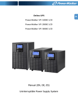
PowerWalker VFI 10000 TP 3/1 REAR VIEW
PowerWalker VFI 20000 TP 3/1 REAR VIEW

10
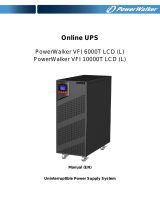
PowerWalker VFI 10000TCP 3/1 REAR VIEW
Fig. 3-1 the rear view of the tower 3-phase series UPS
3.2 Product Specification and Performance
1) General Specification
Model
PowerWalker VFI
10000TP 3/1
PowerWalker VFI
20000TP 3/1
PowerWalker VFI
10000TCP 3/1
Power Rating 10KVA/9KW 20KVA/18KW 10KVA/9KW
Frequency (Hz)
50/60
Input
Voltage
(110-276)VAC (Depends on Load Level)
Current
L1/L2/L3:23A MAX
L1/L2/L3:46A MAX
L1/L2/L3:23A MAX
Battery
Voltage
288VDC 240VDC
Parallel Port
(Optional)
Intelligent Slot
EPO、 、RS232 USB
Fan
AS400
Input Breaker
Terminal Blocks
Cover
External Battery
IEC Connector
Maintenance and Output
Switch Cover

11
Current
43A MAX 86A MAX 51.8A MAX
Output
Voltage
200VAC/208VAC/220VAC/230VAC/ 240VAC*
Current
45A/48.1A/45.5A/4
3.5A/41.7A
90A/96.2A/90.9A/8
7.0A/83.3A
45A/48.1A/45.5A/4
3.5A/41.7A
Dimension
(WxDxH) mm
350x650x890 260*550*708
Net Weight (kg)
127 188 85
2) Electrical Performance
Input
Model Voltage Frequency Power Factor
PowerWalker VFI
10000TP 3/1
PowerWalker VFI
20000TP 3/1
PowerWalker VFI
10000TCP 3/1
Three-phase 50/60 Hz±10%
>0.99(@Full load)
*:If
output voltage be set 200V, output power will derating to 90% of power
rating

12
3) Operating Environment
Temperature Humidity Altitude Storage temperature
0°C-45°C
<95% <1000m
-15°C-50°C
Note: if the UPS is installed or used in a place where the altitude is
above than 1000m, the output power must be derated in use, please
refer to the following:
Altitude (M)
1000
1500
2000
2500
3000
3500
4000
4500
5000
Maximum
Power
100%
95% 91% 86% 82% 78% 74% 70% 67%
Output
Voltage
Regulation
Power
Factor
Frequency
tolerance.
Distortion Overload capacity
Current
crest ratio
±1% 0.9 lag
Synchronized
50/60Hz±10%
in Line mode
(AC mode)
±0.1% of
normal
frequency in
Battery mode
THD<2%
Full load
(Linear
Load)/
<5% for
reference
non-linear
load
100%-110% load
transfers to Bypass
mode after 5
minutes
110%-130% load
transfers to Bypass
mode after 1
minutes
130%-150% load
transfers to Bypass
mode after 10
second
>150% load
transfers to Bypass
mode after 2 second
3:1

13
4. Installation
The system may be installed and wired only by qualified
electricians in accordance with applicable safety regulations!
4.1 Unpacking and Inspection
1. Moving to the installation site
The tower 3-phase series UPS has wheels making it easy to move the
UPS to the installation site after it has been unpacked. However, if the
receiving area is far from the installation site, we recommend you to
move the UPS by using a pallet jack or a lifter before you start to
unpack the UPS.
2. Unpacking and inspection
1) At the installation site, the utmost care shall be taken when
removing the packaging in order to avoid damaging the equipment.
Check all packaging materials to ensure that no items are missing.
The shipping package contains:
● A UPS
● A user manual
● A communication cable
● Parallel port cover plate

14
Remove the packaging following the sequence illustrated in Fig. 4-1 to
Fig. 4-4. (only for PowerWalker VFI 10000-20000 TP 3/1)
Tools kit
Lifter
Phillips screwdriver
Scissors
Wrench
Fig. 4-1 Unpacking-step1 Fig. 4-2 Unpacking-step2

15
The shipping materials are recyclable. After unpacking,
save them for later use or dispose of them appropriately.
2) Inspect the appearance of the UPS to see if there is any damage
during transportation. Do not turn on the unit and notify the carrier
and dealer immediately if there is any damage or lacking of some
parts.
Fig. 4-3 Unpacking-step3 Fig. 4-4 Unpacking-step4

16
4.2 Input and Output Power Cords and Protective
Earth Ground Installation
1. Notes for installation
1) The UPS must be installed in a location with good ventilation, far
away from water, inflammable gas and corrosive agents.
2) Ensure the air vents on the front and rear of the UPS are not
blocked. Allow at least 0.5m of space on each side.
3) Condensation to water drops may occur if the UPS is unpacked in a
very low temperature environment. In this case it is necessary to
wait until the UPS is fully dried inside out before proceeding
installation and use. Otherwise there are hazards of electric shock.
4) Once the installation is completed, the side mounting brackets
(used in shipping)shall be fixed back to ensure the stability of the
UPS enclosure. If impossible, additional stability can be added by
anchoring the mounting brackets to the floor with M8 bolts. See Fig.
4-5. (only for PowerWalker VFI 10000-20000 TP 3/1)
Fig. 4-5 Additional stability
2. Installation
Installation and wiring must be performed in accordance with the
local electric code and the following instructions by professional
personnel.

17
For safety, please cut off the mains power switch before installation.
1) Open the terminal block cover located on the rear panel of the
UPS, please refer to the appearance diagram.
2) For tower PowerWalker VFI 10000TCP 3/1 UPS, it is
recommended to select the UL1015 8AWG(10mm
2
) wire or other
insulated wire which complies with AWG Standard for the UPS
input and output wirings.
3) For PowerWalker VFI 20000TP 3/1 UPS, it is recommended to
select the UL1015 6AWG(25mm
2
) wire or other insulated wire
which complies with AWG Standard for the UPS input and output
wirings.
Note: Do not use the wall receptacle as the input power source
for the UPS, as its rated current is less than the UPS’s
maximum input current. Otherwise the receptacle may be
burned and destroyed.
4) Connect the input and output wires to the corresponding input
and output terminals according to the following diagram.
Note: you must make sure that the input and output wires and
the input and output terminals are connected tightly.
5) The protective earth ground wire refers to the wire connection
between the equipment which consumes electric equipment and
the ground wire. The wire diameter of protective earth ground
wire should be at least as above mentioned for each model and
green wire or green wire with yellow ribbon wire is used.
6) After having completed the installation, make sure the wiring is
correct.
7) Please install the output breaker between the output terminal
and the load, and the breaker should with leakage current
protective function if necessary.
/